
Related Manuals for Alfa Laval T6-BZM


Summary of Contents for Alfa Laval T6-BZM
- Page 1 Gasketed plate-and-frame heat exchangers Industrial line – T6–BZM, T6–PZM, T10–BZM, T10–MZM Instruction Manual Lit. Code 200000807-1-EN-GB...
- Page 2 Alfa Laval Corporate AB 2019-03 This document and its contents are subject to copyrights and other intellectual property rights owned by Alfa Laval Corporate AB. No part of this document may be copied, re-produced or transmitted in any form or by any means, or for any purpose, without Alfa Laval Corporate AB’s prior express written permission. Information and services provided in this document are made as a benefit and service to the user, and no representations or warranties are made about the accuracy or suitability of this information and these services for any purpose.
- Page 3 English Italiano Download local language versions of this instruction Scarica la versione in lingua locale del manuale di manual from www.alfalaval.com/gphe-manuals or use istruzioni da www.alfalaval.com/gphe-manuals oppure the QR code utilizza il codice QR. Český 日本の Stáhněte si místní jazykovou verzi tohoto návodu k www.alfalaval.com/gphe-manuals からご自分の言語の...
- Page 4 Slovenski Prenesite različice uporabniškega priročnika v svojem jeziku s spletne strani www.alfalaval.com/gphe- manuals ali uporabite kodo QR. Slovenský Miestne jazykové verzie tohto návodu na používanie si stiahnite z www.alfalaval.com/gphe-manuals alebo použite QR kód. Svenska Ladda ned lokala språkversioner av denna bruksanvisning från www.alfalaval.com/gphe-manuals eller använd QR-koden.
-
Page 5: Table Of Contents
Table of contents 1 Preface ..........................7 Conditions and Requirements................... 7 Environmental compliance..................7 2 Safety ..........................9 Safety considerations....................9 Definitions of expressions..................9 3 Description ........................11 Components......................11 Name plate......................13 Function........................15 Identification of plate side..................16 4 Installation ........................ -
Page 7: Preface
Maintenance and installation of the heat exchanger shall be done by persons who have knowledge and authorization according to local regulations. This may include actions such as piping, welding and other kind of maintenance. For maintenance actions not described in this manual, contact your Alfa Laval representative for advice. PHE drawings PHE (plate heat exchanger) drawings mentioned in the manual are the drawings included in the delivery of the heat exchanger. - Page 8 1 Preface Unpacking Packing material consists of wood, plastics, cardboard boxes and, in some cases, metal straps. • Wood and cardboard boxes can be reused, recycled or used for energy recovery. • Plastics should be recycled or burnt at a licensed waste incineration plant. •...
-
Page 9: Safety
Laval’s instructions in this manual. Incorrect handling of the heat exchanger may result in serious consequences with injuries to persons and/or property damage. Alfa Laval will not accept responsibility for any damage or injury resulting from not following the instructions in this manual. - Page 10 2 Safety 200000807-1-EN-GB...
-
Page 11: Description
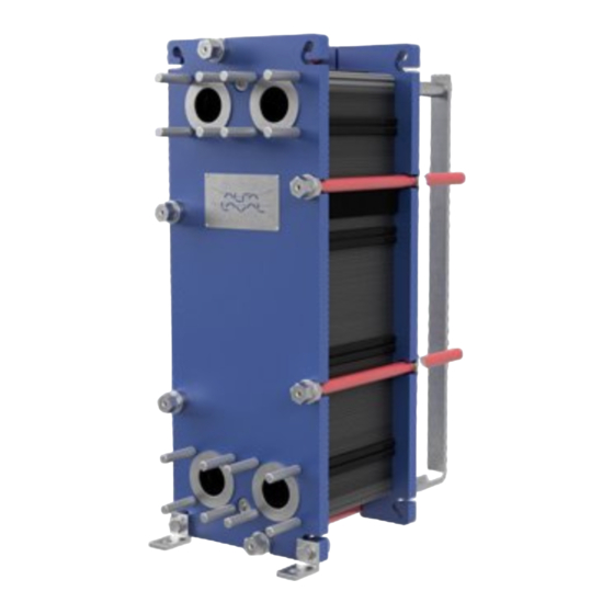
3 Description 3.1 Components Main components 1. Frame plate Fixed plate with a various number of portholes for the connection of the piping system. The carrying and guiding bar are attached to the frame plate. 2. Carrying bar Carries the plate pack and the pressure plate 3. - Page 12 3 Description 7. Tightening bolts Compress the plate pack between the frame plate and the pressure plate. There are usually four tightening bolts used, in some cases six, these are used to open and close the heat exchanger. Remaining bolts are used as locking bolts. 8.
-
Page 13: Name Plate
Description 3 3.2 Name plate The type of unit, manufacturing number and manufacturing year can be found on the name plate. Pressure vessel details in accordance with the applicable pressure vessel code are also given. The name plate is fixed to the frame plate, most commonly, or the pressure plate. - Page 14 3 Description Manufacturer Type Serial No. MANUFACTURER: Year YEAR OF MANUFACTURING: Fluid group TYPE: SERIAL NUMBER: Inlet Outlet Volume → → Allowable press. INLET → OUTLET Min./Max. FLUID GROUP VOLUME Allowable temp. MAX. OP. TEMP. Min./Max. TS ALLOWABLE PRESS. Manufacturer MIN./MAX.
-
Page 15: Function
Description 3 3.3 Function The heat exchanger consists of a pack of corrugated metal plates with portholes for the input and output of the two separate fluids. The heat transfer between the two fluids takes place through the plates. The plate pack is assembled between a frame plate and a pressure plate and compressed by tightening bolts. -
Page 16: Identification Of Plate Side
3 Description 3.4 Identification of plate side The A side of the plates (symmetric pattern) are identified by a stamp with the letter A and the model name at the top of the plate (refer to image 1 below). Plates with asymmetric pattern has two possible sides for placement of the gaskets. -
Page 17: Installation
4 Installation 4.1 Before installation CAUTION During installation or maintenance, precautions must be taken to avoid damaging the heat exchanger and its components. Damage to components can adversely affect the performance or serviceability of the heat exchanger. To consider before installation •... -
Page 18: Requirements
4 Installation 4.2 Requirements Space Please refer to the delivered PHE drawing for actual measurements. 1. Free space is required for lifting plates in and out. 2. Free space is required under the lower tightening/locking bolt for maintenance. 3. Supports for the guiding bar may be needed. 4. -
Page 19: Lifting
Use of other attachment points or strap load directions than those described are not allowed. If the heat exchanger is not supplied with lifting devices from Alfa Laval, the corresponding equipment must be selected and the same attachment points must be used. -
Page 20: Raising
4 Installation 4.4 Raising This instruction is valid when raising the heat exchanger after delivery from Alfa Laval. Only use a strap approved for the weight of the heat exchanger. Follow the principle of the instruction below. CAUTION The straps shall be long enough to be able to rotate the heat exchanger without obstruction. - Page 21 Installation 4 Lift the heat exchanger off the timber beams. Lower the heat exchanger into a horizontal position and place it on the floor. 200000807-1-EN-GB...
- Page 22 4 Installation 200000807-1-EN-GB...
-
Page 23: Operation
5 Operation 5.1 Start-up During the start-up, check that there are no visible leakages from the plate pack, valves or piping system. CAUTION Before pressurizing the heat exchanger, it is important to ensure that the temperature of the heat exchanger is within the temperature range as stated in the PHE drawing. CAUTION If the temperature of the heat exchanger is below the minimum temperature for the gaskets prior to the service, it is recommended to heat the heat exchanger above this limit to avoid cold... - Page 24 5 Operation Check that the valve is closed between the pump and the unit controlling the system flow rate to avoid pressure surge. If there is a vent valve installed at the exit, make sure it is fully open. Increase the flow rate slowly. Open the air vent and start the pump.
-
Page 25: Unit In Operation
Operation 5 5.2 Unit in operation Adjustments of flow rates should be made slowly in order to protect the system against sudden and extreme variations of temperature and pressure. During operation, check that media temperatures and pressures are within the limits stated on the name plate and the PHE drawing. - Page 26 5 Operation 200000807-1-EN-GB...
-
Page 27: Maintenance
Different methods can be used for cleaning (refer to Cleaning – Non-product side on page 27) or reconditioning can be performed at an Alfa Laval service center. After a long period of use, it can be required to regasket the heat exchanger. - Page 28 6 Maintenance WARNING The residuals after a cleaning procedure shall be handled according to local environmental regulations. After neutralization most cleaning solutions may be drained into the waste water system under the condition that the fouling deposits do not contain heavy metals or other toxic or environmentally dangerous compounds.
-
Page 29: Opening
During manual cleaning, it is necessary to open the heat exchanger to clean the plates. NOTE Before opening the heat exchanger, check the warranty conditions. If in any doubt, contact the Alfa Laval sales representative. Refer to Warranty conditions on page 7. -
Page 30: Opening Procedure
6 Maintenance 6.2.2 Opening procedure Shut down the heat exchanger. Close the valves and isolate the heat exchanger from the rest of the system. Drain the heat exchanger. NOTE Avoid vacuum in the heat exchanger by opening vent valves. Remove the protection sheets, if any. Inspect the sliding surfaces of the carrying bar and wipe clean and grease. - Page 31 Maintenance 6 Measure and note the dimension. T6 and T10 heat exchanger models using divided bars locked by a nut. Remove nuts, guiding bar support foot, outer bar ends, nuts and washers. Reassemble in the following order; outer bar ends, support foot, washers and nuts. NOTE Opening T6 and T10 heat exchanger models will wear out the carrying and...
- Page 32 6 Maintenance 10 Use the tightening bolts to open the heat exchanger. During the opening procedure, keep the frame plate and pressure plate parallel. Skewing of the pressure plate during opening must not exceed 10 mm (2 turns per bolt) across the width and 25 mm (5 turns per bolt) vertically.
-
Page 33: Manual Cleaning Of Opened Units
Maintenance 6 6.3 Manual cleaning of opened units CAUTION Never use hydrochloric acid with stainless steel plates. Water of more than 330 ppm Cl may not be used in the preparation of cleaning solutions. It is very important that aluminium carrying bars and support columns are protected against chemicals. -
Page 34: Closing
Check that all the sealing surfaces are clean. Brush the threads of the bolts clean, using a steel wire brush or the Alfa Laval thread cleaner. Lubricate the threads with a thin layer of grease, e.g. Gleitmo 800 or its equivalent. - Page 35 Maintenance 6 T6 and T10 heat exchanger models using divided bars locked by a nut. Remove nuts, washers, guiding bar support foot and outer bar ends. Reassemble in the following order; washers, nuts, outer bar ends, guiding bar support foot, and nuts.
- Page 36 6 Maintenance Tighten the four bolts (1), (2), (3), (4) evenly until dimension A has been reached. When a pneumatic tightening device is used, see table below for maximum torque. Measure dimension A during tightening. Bolt with washer Bolt size 13.5 26.5 For manual tightening, the tightening torque...
-
Page 37: Pressure Test After Maintenance
Example of a rebuilding is that more number of plates are added to the plate pack. If there is any uncertainty about the testing procedure of the heat exchanger, consult an Alfa Laval representative. 6.6 Regasketing The procedures below concern field gaskets, ring gaskets and end gaskets. -
Page 38: Clip-On / Clipgrip
29, and remove the plate that is to have a new gasket. NOTE Before opening the heat exchanger, check the warranty conditions. If in any doubt, contact the Alfa Laval sales representative. Refer to Warranty conditions on page 7. -
Page 39: Storage Of The Heat Exchanger
7 Storage of the heat exchanger Alfa Laval delivers the heat exchanger ready to be put into service upon arrival, if nothing else has been agreed. Nevertheless, keep the heat exchanger in the packing box until installation. If storing for longer periods of time, such as one month or longer, certain precautions should be made to avoid unnecessary damage to the heat exchanger. -
Page 40: Taken Out Of Service
Closing on page 34. 6. Alfa Laval recommends a hydraulic test should be carried out. The media, usually water, should be entered at intervals to avoid sudden shocks to the heat exchanger. It is recommended to test up to the Design Pressure.
Need help?
Do you have a question about the T6-BZM and is the answer not in the manual?
Questions and answers