Table of Contents
Advertisement
Quick Links
Advertisement
Table of Contents

Related Manuals for Kostal INVEOR P


Summary of Contents for Kostal INVEOR P
- Page 1 Operating manual INVEOR P Drive Controller...
- Page 2 This manual may not be reproduced, stored, transmitted or translated in any form or by means of any medium - in whole or in part - without prior written permission. Operating manual for INVEOR P | DOC01695343-0001 | 2016-03 | V2.00 EN...
-
Page 3: Table Of Contents
Scope of delivery ................30 2.2.1 Scope of delivery for INVEOR P size Alpha ........30 2.2.2 Scope of delivery for INVEOR P size A - D ......... 31 Description of INVEOR P drive controller ........... 32 Installation ..................33 Safety instructions for installation ............ - Page 4 (INVEOR P size A IV01 [3 x 400 V AC]) ..........41 3.3.5 Basic connection versions (INVEOR P size B IV01 [3 x 400 V AC]) ..43 3.3.6 Basic connection versions (INVEOR P size C IV01 [3 x 400 V AC]) ..45 3.3.7 Basic connection versions (INVEOR P size D IV01 [3 x 400 V AC]) ..
- Page 5 Standards and guidelines ..............92 10.4 UL approval ..................93 10.4.1 UL Specification (English version)............93 10.4.2 Homologation CL (Version en française) ..........96 Mentions obligatoires ................98 Index ....................101 Operating manual for INVEOR P | DOC01695343-0001 | 2016-03 | V2.00 EN...
-
Page 6: General Information
1.10.2 Transport & storage ................23 1.10.3 Information about commissioning ............23 1.10.4 Instructions concerning operation ............25 1.10.5 Maintenance and inspection .............. 26 1.10.6 Repairs ....................27 Operating manual for INVEOR P | DOC01695343-0001 | 2016-03 | V2.00 EN... -
Page 7: Information About Documentation
G e n e r a l i n f o r m a t i o n Thank you for choosing an INVEOR P drive controller (Cold Plate) from KOSTAL Industrie Elektrik GmbH! Our INVEOR line of drive controllers is designed to be universally usable with all common motor types. -
Page 8: Other Applicable Documents
1.1.2 Storing the documentation Store this operating manual and all other applicable documents carefully so they are available when needed. Operating manual for INVEOR P | DOC01695343-0001 | 2016-03 | V2.00 EN... -
Page 9: Notes In This Manual
Possible consequence(s) of failure to comply Corrective actions 1.2.2 Warning symbols used Danger Danger due to electrical shock and discharge Danger due to burns Danger due to electromagnetic fields Operating manual for INVEOR P | DOC01695343-0001 | 2016-03 | V2.00 EN... -
Page 10: Signal Words
IMPORTANT INFORMATION The drive controller may only be assembled, operated, maintained and installed by trained and qualified staff. Fig.: 2 Example of an information note 10 Operating manual for INVEOR P | DOC01695343-0001 | 2016-03 | V2.00 EN... -
Page 11: Symbols Used In This Manual
Effect of a handling instruction Final result of a handling instruction List Fig.: 3 Symbols and icons used Abbreviations used Abbreviation Explanation Tab. Table Fig. Figure Item Chapter Operating manual for INVEOR P | DOC01695343-0001 | 2016-03 | V2.00 EN 11... -
Page 12: Labels On The Drive Controller
Danger due to electrical shock and discharge Danger due to electrical shock and discharge. Wait two minutes (discharge time of the capacitors) after shut- down Additional earth connection Observe and read operating manual 12 Operating manual for INVEOR P | DOC01695343-0001 | 2016-03 | V2.00 EN... -
Page 13: Qualified Staff
Using drive controllers in equipment that is not fixed is considered as an exceptional environmental condition and is only permitted if allowed by the standards and guidelines applicable on site. Operating manual for INVEOR P | DOC01695343-0001 | 2016-03 | V2.00 EN 13... -
Page 14: Responsibility
DIN EN 13849 “Safety of machinery – Safety-related parts of control systems”. 14 Operating manual for INVEOR P | DOC01695343-0001 | 2016-03 | V2.00 EN... -
Page 15: Eu Declaration Of Conformity
. IMPORTANT INFORMATION CE marking is the sole responsibility of the distributor. Note the project planning information (chapter 1.9) for details. Operating manual for INVEOR P | DOC01695343-0001 | 2016-03 | V2.00 EN 15... -
Page 16: Project Planning Information For Housing Design
95 °C (measured in the power module) with the error message "IGBT temperature". 16 Operating manual for INVEOR P | DOC01695343-0001 | 2016-03 | V2.00 EN... - Page 17 Active cooling plate dimensions Size Output Active cooling surfaces [kW] B [mm] H [mm] Alpha 0.75 261.5 Operating manual for INVEOR P | DOC01695343-0001 | 2016-03 | V2.00 EN 17...
- Page 18 20-pin ribbon cable. Use an insulating film with a voltage resistance of at least 600 V at points where this spacing isn't provided. 18 Operating manual for INVEOR P | DOC01695343-0001 | 2016-03 | V2.00 EN...
- Page 19 Death or serious injury! Live parts Attach a warning notice in accordance with IEC 60417-5036 (2002- 10) to the last housing part removed (with tool) before accessing live parts. Operating manual for INVEOR P | DOC01695343-0001 | 2016-03 | V2.00 EN 19...
- Page 20 Fires may result. The INVEOR standard housing is not critical in this regard. 20 Operating manual for INVEOR P | DOC01695343-0001 | 2016-03 | V2.00 EN...
-
Page 21: Safety Instructions
KOSTAL Industrie Elektrik GmbH. Keep the operating manual close to the drive controller so it is easily accessible to all users. Operating manual for INVEOR P | DOC01695343-0001 | 2016-03 | V2.00 EN 21... - Page 22 Do not modify the drive controller. Only use spare parts and accessories sold or recommended by the manufacturer. During assembly, ensure a sufficient distance from neighbouring parts. 22 Operating manual for INVEOR P | DOC01695343-0001 | 2016-03 | V2.00 EN...
-
Page 23: Transport & Storage
(INV. A-D): L1, L2, L3 Motor connection X411 (INV. Alpha): U, V, W terminals (INV. Α-D): U, V, W Relay connection X6, X7 terminals PTC terminals T1/ T2 Operating manual for INVEOR P | DOC01695343-0001 | 2016-03 | V2.00 EN 23... - Page 24 The drive controller contains components susceptible to electrical discharge. These may be destroyed through improper handling. Therefore, precautionary measures against electrostatic charges must be taken when work is performed on these components. 24 Operating manual for INVEOR P | DOC01695343-0001 | 2016-03 | V2.00 EN...
-
Page 25: Instructions Concerning Operation
D . Certain parameter settings may result in the drive controller restarting automatically after the supply voltage has failed. Operating manual for INVEOR P | DOC01695343-0001 | 2016-03 | V2.00 EN 25... -
Page 26: Maintenance And Inspection
KOSTAL experts or persons authorised by KOSTAL. Measurement of insulation resistance on control part An insulation test on the control card's input terminals is not permitted. 26 Operating manual for INVEOR P | DOC01695343-0001 | 2016-03 | V2.00 EN... -
Page 27: Repairs
De-energise drive controller and secure it against being restarted. D anger due to electrical shock and discharge. Wait two minutes (discharge time of the capacitors) after shut-down Operating manual for INVEOR P | DOC01695343-0001 | 2016-03 | V2.00 EN 27... -
Page 28: Overview Of The Drive Controller
Scope of delivery ................30 2.2.1 Scope of delivery for INVEOR P size Alpha ........30 2.2.2 Scope of delivery for INVEOR P size A - D ......... 31 Description of INVEOR P drive controller ........... 32 28 Operating manual for INVEOR P | DOC01695343-0001 | 2016-03 | V2.00 EN... -
Page 29: Model Description Size Alpha, Size A - D
SW3.8x) Housing type α GH03 Sandwich Cover type α DK03 without cover Model α KOSTAL - CO00 standard INV Px IVxx PWxx LPxx APxx GHxx DKxx COxx Operating manual for INVEOR P | DOC01695343-0001 | 2016-03 | V2.00 EN 29... -
Page 30: Scope Of Delivery
Fig.: 5 Scope of delivery for INVEOR P size Alpha Drive controller article number Adapter plate article number INVEOR P drive controller size Alpha Motor terminal Mains terminal Operating manual Bridge M5 x 12 PE screw 30 Operating manual for INVEOR P | DOC01695343-0001 | 2016-03 | V2.00 EN... -
Page 31: Scope Of Delivery For Inveor P Size A - D
INVEOR P drive controller size A IV01 M5 x 12 PE screw INVEOR P drive controller size B IV01 Operating manual INVEOR P drive controller size C IV01 Operating manual for INVEOR P | DOC01695343-0001 | 2016-03 | V2.00 EN 31... -
Page 32: Description Of Inveor P Drive Controller
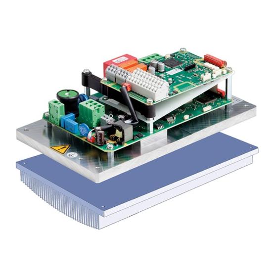
O v e r v i e w o f t h e d r i v e c o n t r o l l e r 2.3 Description of INVEOR P drive controller The INVEOR P drive controller is a device for speed control in three-phase AC motors. -
Page 33: Installation
(INVEOR P size A IV01 [3 x 400 V AC]) ..........41 3.3.5 Basic connection versions (INVEOR P size B IV01 [3 x 400 V AC]) ..43 3.3.6 Basic connection versions (INVEOR P size C IV01 [3 x 400 V AC]) ..45 3.3.7 Basic connection versions (INVEOR P size D IV01 [3 x 400 V AC]) .. -
Page 34: Safety Instructions For Installation
Mains connections must be hardwired. CAUTION Risk of burns from hot surfaces! Serious burns to the skin from hot surfaces! Allow the drive controller's cooling elements to cool sufficiently. 34 Operating manual for INVEOR P | DOC01695343-0001 | 2016-03 | V2.00 EN... -
Page 35: Recommended Preliminary Fuses / Line Protection
The cross-section of the supply line must be designed according to the transfer category and maximum permitted current. The contractor commissioning the device must ensure protection for the power line. Operating manual for INVEOR P | DOC01695343-0001 | 2016-03 | V2.00 EN 35... -
Page 36: Installation Requirements For Inveor P Size Alpha
Disassembling the circuit boards renders the warranty void! Mounting points and sealing surfaces must be kept free of paint for purposes of EMC and grounding! 36 Operating manual for INVEOR P | DOC01695343-0001 | 2016-03 | V2.00 EN... -
Page 37: Basic Connection Versions/Power Connections (Inveor P Size Alpha)
Mains phase Neutral wire Earth connection point DANGER Risk of death due to electrical shock! Death or serious injury! De-energise drive controller and secure it against being restarted. Operating manual for INVEOR P | DOC01695343-0001 | 2016-03 | V2.00 EN 37... - Page 38 The cross-section of the supply line must be designed according to the transfer category and maximum permitted current. The contractor commissioning the device must ensure protection for the power line . 38 Operating manual for INVEOR P | DOC01695343-0001 | 2016-03 | V2.00 EN...
-
Page 39: (Inveor P Size A 1 Iv02 [1 X 230 V Ac])
Terminal assignment X15 Earth connection point DANGER Risk of death due to electrical shock! Death or serious injury! De-energise drive controller and secure it against being restarted. Operating manual for INVEOR P | DOC01695343-0001 | 2016-03 | V2.00 EN 39... - Page 40 The terminals for the mains cable (X1) are located on the IPM printed circuit board. The INVEOR P also has the option of being equipped with terminals (X3) for connecting a brake resistor. The configuration may vary depending on the version.
-
Page 41: (Inveor P Size A Iv01 [3 X 400 V Ac])
Terminal assignment X15 Earth connection point DANGER Risk of death due to electrical shock! Death or serious injury! De-energise drive controller and secure it against being restarted. Operating manual for INVEOR P | DOC01695343-0001 | 2016-03 | V2.00 EN 41... - Page 42 The terminals for the mains cable (X1) are located on the IPM printed circuit board. The INVEOR P also has the option of being equipped with terminals (X3) for connecting a brake resistor. The configuration may vary depending on the version.
-
Page 43: Basic Connection Versions (Inveor P Size B Iv01 [3 X 400 V Ac])
Terminal assignment X15 Earth connection point DANGER Risk of death due to electrical shock! Death or serious injury! De-energise drive controller and secure it against being restarted. Operating manual for INVEOR P | DOC01695343-0001 | 2016-03 | V2.00 EN 43... - Page 44 The terminals for the mains cable (X1) are located on the IPM printed circuit board. The INVEOR P also has the option of being equipped with terminals (X3) for connecting a brake resistor. The configuration may vary depending on the version.
-
Page 45: Basic Connection Versions (Inveor P Size C Iv01 [3 X 400 V Ac])
Terminal assignment X5 Earth connection point DANGER Risk of death due to electrical shock! Death or serious injury! De-energise drive controller and secure it against being restarted. Operating manual for INVEOR P | DOC01695343-0001 | 2016-03 | V2.00 EN 45... - Page 46 The terminals for the mains cable (X1) are located on the IPM printed circuit board. The INVEOR P also has the option of being equipped with terminals (X3) for connecting a brake resistor. The configuration may vary depending on the version.
-
Page 47: Basic Connection Versions (Inveor P Size D Iv01 [3 X 400 V Ac])
Motor temperature (-) Motor temperature (+) DANGER Risk of death due to electrical shock! Death or serious injury! De-energise drive controller and secure it against being restarted. Operating manual for INVEOR P | DOC01695343-0001 | 2016-03 | V2.00 EN 47... - Page 48 The terminals for the mains cable (X1) are located on the IPM printed circuit board. The INVEOR P also has the option of being equipped with terminals (X2) for connecting a brake resistor. The configuration may vary depending on the version.
-
Page 49: Short Circuit And Ground Protection
IGBT (brake chopper): - Short circuit - Short circuit to earth / earth fault - Fire - Explosion - Melting of aluminium housing of resistor Operating manual for INVEOR P | DOC01695343-0001 | 2016-03 | V2.00 EN 49... -
Page 50: Wiring Instructions
0.5 to 1.0 mm², fine-wired (core end sleeves with and without plastic collars) Length of stripped 9 to 10 mm insulation: For technical data on power connections, see chapter 3.3.2. 50 Operating manual for INVEOR P | DOC01695343-0001 | 2016-03 | V2.00 EN... -
Page 51: Wiring Instructions For Control Terminals Inveor P Size A-D
0.75 to 1.5 mm², fine-wired, AWG 18 to AWG 14 section: Connection cross- 0.5 to 1.0 mm², fine-wired section: (core end sleeves with and without plastic collars) Length of stripped 9 to 10 mm insulation: Operating manual for INVEOR P | DOC01695343-0001 | 2016-03 | V2.00 EN 51... -
Page 52: Preventing Electromagnetic Interferences
The use of EMC cable screw connections is recommended. These are not part of the scope of delivery. Wiring suitable for EMC must be ensured. 52 Operating manual for INVEOR P | DOC01695343-0001 | 2016-03 | V2.00 EN... -
Page 53: Installing The Inveor P
3. Place the INVEOR P in the desired position. 4. Tightly connect the INVEOR P with the thermal sink. IMPORTANT INFORMATION During installation, ensure that the connection cable is not crushed! Operating manual for INVEOR P | DOC01695343-0001 | 2016-03 | V2.00 EN 53... -
Page 54: Wiring Diagram For Inveor P Size Alpha
The drive controller is ready once a 230 V AC mains supply has been activated (on terminals L and N) or a 325 V DC mains supply has been activated (on terminals L and N). 54 Operating manual for INVEOR P | DOC01695343-0001 | 2016-03 | V2.00 EN... -
Page 55: Electrical Installation For Inveor P Size Alpha
If the bridge is not connected, the red status LED lights up and the motor does not start. IMPORTANT INFORMATION Only motor PTCs corresponding to DIN 44081/44082 may be connected! Operating manual for INVEOR P | DOC01695343-0001 | 2016-03 | V2.00 EN 55... - Page 56 De-energise mains cable and secure it against being restarted. 3. Connect mains cables to mains plug (2) as follows: 230 V connection Terminal no. Designation Assignment Mains phase Neutral wire Earth connection point 56 Operating manual for INVEOR P | DOC01695343-0001 | 2016-03 | V2.00 EN...
- Page 57 If a control line is not attached, a bridge must be connected between "24 V Out" and "En. HW". When the bridge is connected, the drive controller's output stage is always enabled. Operating manual for INVEOR P | DOC01695343-0001 | 2016-03 | V2.00 EN 57...
- Page 58 Wiring diagram INVEOR P size Alpha) Relay X6 Designation Assignment Centre contact relay Normally open contact relay Normally closed contact For technical data on power connections, see chapter 3.3.2. 58 Operating manual for INVEOR P | DOC01695343-0001 | 2016-03 | V2.00 EN...
-
Page 59: Electrical Installation For Inveor P Size A-B
De-energise mains cable and secure it against being restarted. 1. Connect mains cables to mains terminal as follows: 230 V connection 400 V connection Continues on next page Operating manual for INVEOR P | DOC01695343-0001 | 2016-03 | V2.00 EN 59... - Page 60 2. Connect the cables of the brake resistor to the terminal (X3) as follows: Connections for brake resistor (X3) (option) Connection for brake resistor (+) Connection for brake resistor (-) Continues on next page 60 Operating manual for INVEOR P | DOC01695343-0001 | 2016-03 | V2.00 EN...
- Page 61 Remove the bridging contact inserted for delivery for this purpose. When the bridge is in place, the temperature of the motor is not monitored! Only motor PTCs corresponding to DIN 44081/44082 may be connected! Operating manual for INVEOR P | DOC01695343-0001 | 2016-03 | V2.00 EN 61...
-
Page 62: Electrical Installation For Inveor P Size C-D
Death or serious injury! De-energise mains cable and secure it against being restarted. 1. Connect mains cables to mains terminal (X1) as follows: 400 V connection Continues on next page 62 Operating manual for INVEOR P | DOC01695343-0001 | 2016-03 | V2.00 EN... - Page 63 2. Connect the cables of the brake resistor to the terminal (X2/X3) as follows: Connections for brake resistor (X2/X3) (option) Connection for brake resistor (+) Connection for brake resistor (-) Continues on next page Operating manual for INVEOR P | DOC01695343-0001 | 2016-03 | V2.00 EN 63...
- Page 64 Remove the bridging contact inserted for delivery for this purpose. When the bridge is in place, the temperature of the motor is not monitored! Only motor PTCs corresponding to DIN 44081/44082 may be connected! 64 Operating manual for INVEOR P | DOC01695343-0001 | 2016-03 | V2.00 EN...
-
Page 65: Connection Diagram For Inveor P Size A-D
(on terminals L1 to L3) or a 565 V DC mains supply has been activated (on terminals L1 and L3). The drive controller can also be started up by connecting an external 24 V voltage . Operating manual for INVEOR P | DOC01695343-0001 | 2016-03 | V2.00 EN 65... - Page 66 A. In 1 PID actual value (parameter 3.060) A GND (Ground 10 V) Ground A. In 2 Free (not assigned) A GND (ground 10 V) Ground Tab. 2 66 Operating manual for INVEOR P | DOC01695343-0001 | 2016-03 | V2.00 EN...
- Page 67 Dig. In 1 Dig. In 2 Free (not assigned) Dig. In 3 Free (not assigned) Dig. In 4 Error reset (parameter 1.180) En HW (enable) Enable hardware Operating manual for INVEOR P | DOC01695343-0001 | 2016-03 | V2.00 EN 67...
- Page 68 Centre contact relay 1 Normally open relay 1 Normally closed relay 1 Tab. 3 INFORMATION In the factory setting, relay 1 is programmed as “relay error” (parameter 4.190). 68 Operating manual for INVEOR P | DOC01695343-0001 | 2016-03 | V2.00 EN...
- Page 69 Centre contact relay 2 Normally open relay 2 Normally closed relay 2 Tab. 4 INFORMATION In the factory setting, “no function” is assigned to relay 2 (parameter 4.210). Operating manual for INVEOR P | DOC01695343-0001 | 2016-03 | V2.00 EN 69...
- Page 70 10 V Out For ext. voltage divider 24 V Out Int. power supply 24 V Out Int. power supply En HW (enable) Enable hardware GND (ground) Ground 70 Operating manual for INVEOR P | DOC01695343-0001 | 2016-03 | V2.00 EN...
-
Page 71: Commissioning
Commissioning INVEOR P size A-D ........... 71 4.1 Commissioning of INVEOR P size Alpha You will find the "Commissioning" chapter for the INVEOR P (size Alpha) in the detailed operating manual for the INVEOR Alpha. Please download the complete operating manual for the INVEOR Alpha from the download area of our website under the following link: www.kostal-industrie-elektrik.com... -
Page 72: Parameter
Parameters for INVEOR P size A-D ............ 72 5.1 Parameters for INVEOR P size Alpha You will find the "Parameters" chapter for the INVEOR P (size Alpha) in the detailed operating manual for the INVEOR Alpha. Please download the complete operating manual for the INVEOR Alpha from the download area of our website under the following link: www.kostal-industrie-elektrik.com... -
Page 73: Error Detection And Troubleshooting
(size A-D) in the detailed operating manual for the INVEOR. Please download the complete operating manual for the INVEOR from the download area of our website under the following link: www.kostal-industrie-elektrik.com Operating manual for INVEOR P | DOC01695343-0001 | 2016-03 | V2.00 EN 73... -
Page 74: Disassembly And Disposal
Dispose of drive controller, packaging and replaced parts in accordance with the regulations of the country in which the drive controller has been installed. The drive controller may not be disposed of with household waste. 74 Operating manual for INVEOR P | DOC01695343-0001 | 2016-03 | V2.00 EN... -
Page 75: Technical Data
8. Technical data General data ..................76 8.1.1 General technical data for 230 V/400 V devices ........ 76 Operating manual for INVEOR P | DOC01695343-0001 | 2016-03 | V2.00 EN 75... -
Page 76: General Data
C1 Certificates and conformity Tab. 5: Technical data for 230 V and 400 V INVEOR P devices (subject to technical changes) The recommended motor rating is stated for single-phase and three-phase devices based on a grid voltage of 230 VAC and 400 VAC. - Page 77 Auxiliary voltage U = 10 V DC Short-circuit proof Imax = 30 mA Tab. 6: Specification of interfaces (size Alpha) * in accordance with UL-61800-5-1, the maximum allowed is 2 A! Operating manual for INVEOR P | DOC01695343-0001 | 2016-03 | V2.00 EN 77...
- Page 78 Short-circuit proof Imax = 30 mA Tab. 7: Specification of interfaces (size A-D) * in terms of the UL 508C standard, the maximum allowed is 2 A! 78 Operating manual for INVEOR P | DOC01695343-0001 | 2016-03 | V2.00 EN...
-
Page 79: Optional Accessories
MMI M12 plug (JST plug) ..............85 CANopen connection cable ............... 86 PROFIBUS connection cable ............. 87 Ethercat/PROFINET/Sercos III connection cable........ 88 9.10 Thermal conductivity paste ..............89 Operating manual for INVEOR P | DOC01695343-0001 | 2016-03 | V2.00 EN 79... - Page 80 INVEOR P Alpha adapter cable Internal potentiometer MMI M12 plug (JST plug) CANopen connection cable Profibus connection cable Thermal conductivity paste 80 Operating manual for INVEOR P | DOC01695343-0001 | 2016-03 | V2.00 EN...
-
Page 81: Mmi Handheld Controller Including A 3 M
INVEOR! The MMI handheld controller is connected to the M12 interface (option) of the INVEOR P. With the INVEOR P size Alpha, the MMI handheld controller can also be connected to the internal jack plug. The INVEOR Alpha adapter cable (art. -
Page 82: Mmi*/Connecting Cable Pin Assignment
RS485 - B Fig.: 28 M12 plug PIN assignment Description: RJ9 plug connector Signal yellow green brown Attention: The colours may vary! Fig.: 29 RJ9 plug connector Man-machine interface 82 Operating manual for INVEOR P | DOC01695343-0001 | 2016-03 | V2.00 EN... -
Page 83: Pc Communication Cable Usb On M12/Rs485 Plug (Converter Integrated)
(converter integrated) Fig.: 30 PC communication cable USB on M12 plug As an alternative to the MMI handheld controller, an INVEOR P can also be put into operation using the PC communication cable (art no. 10023950) and the INVEORpc software. The "INVEOR Alpha adapter cable" (art. no. 10118219) is also needed for this. -
Page 84: Adapter Cable For Inveor P Size Alpha
O p t i o n a l a c c e s s o r i e s 9.4 Adapter cable for INVEOR P size Alpha Fig.: 31 INVEOR Alpha adapter cable The "INVEOR P Alpha adapter cable" is needed to connect the MMI handheld controller or PC communication cable with the INVEOR P Alpha. IMPORTANT INFORMATION The "INVEOR P Alpha adapter cable"... -
Page 85: Mmi M12 Plug (Jst Plug)
Note that the MMI/PC interface is not intended for connecting several control devices! M12 plug Signal M12 plug Signal assignment assignment 24 V RS485 - A RS485 - B Operating manual for INVEOR P | DOC01695343-0001 | 2016-03 | V2.00 EN 85... -
Page 86: Canopen Connection Cable
CANopen bus system. CANopen connection cable pin assignment JST plug Line colour Signal M12 plug pin assignment assignment black CAN_L white CAN_H blue Not used Not used 86 Operating manual for INVEOR P | DOC01695343-0001 | 2016-03 | V2.00 EN... -
Page 87: Profibus Connection Cable
PROFIBUS bus system. PROFIBUS connection cable pin assignment JST plug Line colour Signal M12 plug pin assignment assignment brown RXD / TXD-P green RXD / TXD-N blue DGND Operating manual for INVEOR P | DOC01695343-0001 | 2016-03 | V2.00 EN 87... -
Page 88: Ethercat/Profinet/Sercos Iii Connection Cable
EtherCAT/PROFINET/Sercos III bus system. Pin assignment for EtherCAT/PROFINET/Sercos III Pin assignment Signal Assignment for RJ 45 plug M12 plug Tx + Tx - Rx + Rx - 88 Operating manual for INVEOR P | DOC01695343-0001 | 2016-03 | V2.00 EN... -
Page 89: Thermal Conductivity Paste
The thermal conductivity paste (art. no: 10139778) improves heat transfer between the cooling plate and thermal sink. For the correct way to apply this paste, please consult chapter 3.5.1 Mechanische Installation. Operating manual for INVEOR P | DOC01695343-0001 | 2016-03 | V2.00 EN 89... -
Page 90: Approvals, Standards And Guidelines
Classification acc. to IEC/EN 61800-3 ..........92 10.3 Standards and guidelines ..............92 10.4 UL approval ..................93 10.4.1 UL Specification (English version)............93 10.4.2 Homologation CL (Version en française) ..........96 90 Operating manual for INVEOR P | DOC01695343-0001 | 2016-03 | V2.00 EN... -
Page 91: Emc Limit Classes
This chapter contains information about electromagnetic compatibility (EMC), and applicable guidelines, norms and standards. Because the INVEOR P device is based on the housed INVEOR M device, the INVEOR P is provided with all filter measures. The system integrator therefore only has to remeasure the integrated... -
Page 92: Classification Acc. To Iec/En 61800-3
10.3 Standards and guidelines The following specifically apply: Directive on Electromagnetic Compatibility (Directive 2004/108/EC Standard: EN 61800-3:2004/A1:2012). Low Voltage Directive (Directive 2006/95/EC Standard EN 61800-5-1:2007) 92 Operating manual for INVEOR P | DOC01695343-0001 | 2016-03 | V2.00 EN... -
Page 93: Ul Approval
INV PB 4** 200 x 40 x 250 ILL. 2 60 °C INV PC 4** 216 x 83 x 300 ILL. 3 65 °C IV 02 IV 01 Operating manual for INVEOR P | DOC01695343-0001 | 2016-03 | V2.00 EN 93... -
Page 94: Internal Overload Protection Operates Within 60 Seconds When Reaching
RATED 240 V (PHASE TO GROUD), SUITABLE FOR OVERVOLTAGE CATEGORY III, AND SHALL PROVIDE PROTECTION FOR A RATED IMPULSE WITHSTAD VOLTAGE PEAK OF 2.5 kV”. CAUTION: “For use in Pollution Degree 2 Environment only”. 94 Operating manual for INVEOR P | DOC01695343-0001 | 2016-03 | V2.00 EN... - Page 95 CAUTION: Use 75 °C copper wires only. CAUTION: "Motor overtemperature sensing is not provided by the drive". CAUTION: "For use in Pollution Degree 2 only." Illustrations Fig.: 38 ILL. 1 Operating manual for INVEOR P | DOC01695343-0001 | 2016-03 | V2.00 EN 95...
-
Page 96: Homologation Cl (Version En Française)
10.4.2 Homologation CL (Version en française) CONDITIONS D’ACCEPTABILITÉ : Usage : usage uniquement réservé aux équipements complets dont l’acceptabilité de la combinaison est déterminée par la société Underwriters Laboratories Inc. 96 Operating manual for INVEOR P | DOC01695343-0001 | 2016-03 | V2.00 EN... -
Page 97: Inv Pa 2
INV PB 4 200 x 40 x 250 ILL. 2 60 °C INV PC 4 216 x 83 x 300 ILL. 3 65 °C IV 02 IV 01 Operating manual for INVEOR P | DOC01695343-0001 | 2016-03 | V2.00 EN 97... -
Page 98: Mentions Obligatoires
CATÉGORIE DE SURTENSION III ET FOURNIR UNE PROTECTION CONTRE UNE TENSION ASSIGNÉE DE TENUE AUX CHOCS DE 2,5 kV ». AVERTISSEMENT : « Uniquement pour utilisation dans un environnement de degré de pollution 2 » 98 Operating manual for INVEOR P | DOC01695343-0001 | 2016-03 | V2.00 EN... - Page 99 AVERTISSEMENT : « La commande ne détecte pas la surchauffe du moteur ». AVERTISSEMENT : « Uniquement pour utilisation dans un environnement de degré de pollution 2 ». Illustrations Fig. : 38 ILL. 1 Operating manual for INVEOR P | DOC01695343-0001 | 2016-03 | V2.00 EN 99...
- Page 100 A p p r o v a l s , s t a n d a r d s a n d g u i d e l i n e s Fig. : 39 FIG. 2 Fig.: 40 100 Operating manual for INVEOR P | DOC01695343-0001 | 2016-03 | V2.00 EN...
-
Page 101: Index
Error detection ........................73 EU Declaration of Conformity ....................15 FI protection switch ........................ 24 Frequency ..........................66 General technical data for 230 V/400 V devices ..............76 Operating manual for INVEOR P | DOC01695343-0001 | 2016-03 | V2.00 EN 101... - Page 102 PC cable ........................... 83 Project planning information for housing design ..............16 Proper use ..........................13 Repairs ............................ 27 Safety instructions ......................21, 34 Standards ..........................92 102 Operating manual for INVEOR P | DOC01695343-0001 | 2016-03 | V2.00 EN...
- Page 103 I n d e x Technical data ......................... 75 Thermal conductivity paste ....................53, 89 Transport & storage ........................ 23 UL 93 Operating manual for INVEOR P | DOC01695343-0001 | 2016-03 | V2.00 EN 103...
- Page 104 KOSTAL Industrie Elektrik GmbH Lange Eck 11 58099 Hagen Deutschland Service-Hotline: +49 2331 8040-848 Telefon: +49 2331 8040-800 Telefax: +49 2331 8040-602 www.kostal-industrie-elektrik.com...
Need help?
Do you have a question about the INVEOR P and is the answer not in the manual?
Questions and answers