
Subscribe to Our Youtube Channel
Related Manuals for FRENCH FITNESS FF-FL30


Summary of Contents for FRENCH FITNESS FF-FL30
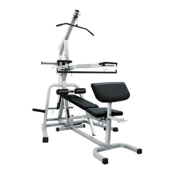
- Page 1 FF-FL30 FRENCH FITNESS FL30 FREEWEIGHT CORNER LEVERAGE GYM ASSEMBLY MANUAL for Bench Only NOTE: Please do not tighten all the screws at the beginning, Wait until all the parts are installed tightening all the screws.
- Page 2 FE AT U RE S • California Residents see Prop 65 WARNINGS ST AT I ONS I NCL U D E D • Lat Pulldown (Tricep Extensions and Lat Pulldowns) • Low Pulley (Seated Rows, Biceps, Abdominal, Leg Raises, Lat Raises, Upright Rows) •...
-
Page 3: Table Of Contents
T ABL E OF CONT E NT S PARTS LIST ......................4 DIAGRAM. STEP 1 ....................5 DIAGRAM. STEP 2 ....................6 DIAGRAM. STEP 3 ....................7 DIAGRAM. STEP 4 ....................8 DIAGRAM. STEP 5 ....................9 DIAGRAM. STEP 6 ....................10... -
Page 4: Parts List
PART S L I ST Figure Figure M6X25 M6X60 M10*20 M10X70 M12X130... -
Page 5: Diagram. Step 1
D I AGRAM. ST E P 1 Step 1 As shown in Figure 1, Assemble part 1 and part 2 . -
Page 6: Diagram. Step 2
D I AGRAM. ST E P 2 Step 2 M6*25------2pcs M6-----2pcs As shown in Figure 2, part 4 is assembled onto part 3 using bolts and gaskets. -
Page 7: Diagram. Step 3
D I AGRAM. ST E P 3 Step 3 M10*70------4pcs M10-----8pcs As shown in Figure 3, part 6 and part 7 are assembled onto part 5 using bolts and gaskets. -
Page 8: Diagram. Step 4
D I AGRAM. ST E P 4 Step 4 M12*130------2pcs M12-----4pcs M12-----2pcs As shown in Figure 4, part 8 and part 9 are assembled onto part 5 using bolts ,gaskets and nuts. -
Page 9: Diagram. Step 5
D I AGRAM. ST E P 5 Step 5 M10*20------2pcs M10-----2pcs As shown in Figure 5, part 10 and part 11 are assembled onto part 5 and part 9 using bolts and gaskets. -
Page 10: Diagram. Step 6
D I AGRAM. ST E P 6 Step 6 M6*25------2pcs M6*60------4pcs M6-----6pcs As shown in Figure 6, part 13 and part 13 are assembled onto part 9 and part 8 using bolts and gaskets.
Need help?
Do you have a question about the FF-FL30 and is the answer not in the manual?
Questions and answers