
Related Manuals for Campbell RF401


Summary of Contents for Campbell RF401
- Page 1 RF401-series and RF430-series Spread Spectrum Data Radios/Modems Revision: 4/17 C o p y r i g h t © 2 0 0 1 - 2 0 1 7 C a m p b e l l S c i e n t i f i c ,...
- Page 3 Quotations for repairs can be given on request. It is the policy of Campbell Scientific to protect the health of its employees and provide a safe working environment, in support of this policy a “Declaration of Hazardous Material and Decontamination”...
- Page 5 PLEASE READ FIRST About this manual Please note that this manual was originally produced by Campbell Scientific Inc. primarily for the North American market. Some spellings, weights and measures may reflect this origin. Some useful conversion factors: Area: 1 in...
- Page 7 • Periodically (at least yearly) check electrical ground connections. WHILE EVERY ATTEMPT IS MADE TO EMBODY THE HIGHEST DEGREE OF SAFETY IN ALL CAMPBELL SCIENTIFIC PRODUCTS, THE CUSTOMER ASSUMES ALL RISK FROM ANY INJURY RESULTING FROM IMPROPER INSTALLATION, USE, OR MAINTENANCE OF TRIPODS, TOWERS, OR ATTACHMENTS TO TRIPODS AND TOWERS...
- Page 9 Where an AC adapter is used, CSI recommends Item # 15966. Any other AC adapter used must have a DC output not exceeding 16.5 Volts measured without a load to avoid damage to the RF401/RF430 Series radio! Over-voltage damage is not covered by factory warranty! (See Section 4.2, Power Supplies...
-
Page 11: Table Of Contents
3. Installation ..............6 Site Considerations ................6 Quick Start (Point-to-Point or PakBus) ..........6 3.2.1 Step 1 – Set Up Base RF401 or RF430 ......... 6 3.2.2 Step 2 – Set Up Remote RF401 ............ 9 3.2.3 Step 3 – LoggerNet Set-up ............10 3.2.4... - Page 12 Example Setup 2 - Router to CR206(X) .......... D-7 E. Port Pin Descriptions ..........E-1 F. Non-PakBus Example Configurations ....F-1 Direct PC to RF401 Series Base Station Setup (Transparent Protocol) ..................F-1 Remote Station Setup (Transparent Protocol) ........F-2 LoggerNet Configuration (Transparent Protocol) ......
- Page 13 Optimization ................... M-4 Idiosyncrasies .................. M-4 Figures 1-1. The RF401 is one of the models available of our RF401-series radios....................2 1-2. RF430 has a USB port allowing it to be connected directly to a PC’s USB port.................. 3 3-1.
- Page 14 Table of Contents 5-1. Default DevConfig Screen for Setting Up the RF401 radios (OS4 or higher) ..................23 5-2. PakBus tab in DevConfig (with Default Settings) ......28 5-3. Select RF4XX for connection type for a multipoint (non PakBus) network..................30 5-4.
- Page 15 Table of Contents H-1. 900 MHz Distance vs. Path Loss (Lp in dB) per Three Path Types ................... H-6 H-2. Path Type vs. Path Characteristics Selector ........H-6 K-1. 900 MHz Gain Antenna Test Distances .......... K-6 L-1. Advanced Setup Menu ..............L-1...
- Page 16 Table of Contents...
-
Page 17: Introduction
This allows the communications to be more immune to noise and interference from RF sources such as pagers, cellular phones and multipath. The RF401-series and RF430- series radios reduce susceptibility to RF interference from other spread spectrum devices by providing user-selectable frequency hopping patterns. -
Page 18: Rf401-Series Radios
RF401-series and RF430-series Spread Spectrum Radio/Modems RF401-series Radios The RF401-series radios have a CS I/O port and an RS-232 port (see FIGURE 1-1). These radios can serve as a field modem/radio while connected to the datalogger or as a base station modem/radio when connected to a PC’s RS-232 port. -
Page 19: Combination Mode Communications
Besides the “direct” to PC communications described in the Quick Start and Installation sections, it is possible to combine methods in datalogger communications. Some examples: • Phone to RF401: PC to external modem to COM220 to RF401 to datalogger (see Appendix I, Phone to RF401 Series (p. I-1) -
Page 20: Retired Spread Spectrum Radios
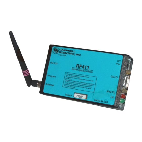
Retired Spread Spectrum Radios 1.4.1 RF400-series Radios On May 2, 2005, the RF401, RF411, and RF416 replaced the RF400, RF410, and RF415, respectively. The newer radios have a choice of three communication protocol settings. The three protocol settings are Transparent, PakBus Aware, and PakBus Node. - Page 21 RF401, RF430 – 9XStream XO9-009 RF411, RF431 – 9XStream XH9-009 RF416, RF432 – 24XStream X24-009 Frequency bands: RF401, RF430 – 910.5 to 917.7 MHz RF411, RF431 – 920.0 to 927.2 MHz RF416, RF432 – 2.45015 to 2.45975 GHz Interface ports:...
-
Page 22: Installation
(p. 12) (p. 16) antenna considerations and options.) If using an RF430, go to step c. If using an RF401, use the RS-232 serial cable to connect the RF401’s RS-232 port to the PC’s RS-232 port. Then go to step d. -
Page 23: Pc Driver Installation
RF401-series and RF430-series Spread Spectrum Radio/Modems If using an RF430, install the USB drivers to the PC by doing the following procedures. Install drivers BEFORE connecting the RF430 to the PC. NOTE You cannot use the RS-232 port to configure the radio. -
Page 24: Or Higher)
RF401-series and RF430-series Spread Spectrum Radio/Modems If using an RF401, plug AC adapter into AC outlet and plug barrel connector into the base radio’s “Power” jack. The RF430 is powered through its USB port. After connecting the radio to its power source, you will see the red “Pwr/TX”... -
Page 25: Step 2 - Set Up Remote Rf401
(p. 16) Use the SC12 serial cable to connect the datalogger CS I/O port to the remote RF401 radio’s CS I/O port. The CS I/O port on newer dataloggers applies power to the remote RF401. With older dataloggers lacking 12 V on pin 8 (see TABLE 3-2), you can power the RF401 using a Field Power Cable (see above hardware list) between the datalogger’s 12 V (output) terminals and the RF401’s... -
Page 26: Step 3 - Loggernet Set-Up
PS512M Power Supply < 1712 When you connect power to the RF401 (through the SC12 cable or the optional Field Power Cable) you should see the power-up sequence of red and green LEDs described in Step 1 (assuming datalogger is powered). -
Page 27: Step 4 - Connect
RF401-series and RF430-series Spread Spectrum Radio/Modems For the datalogger settings, set the Baud Rate to match the radio’s RS-232 baud rate. (The radio’s default RS-232 baud rate is 38.4 kbps.) The datalogger “Extra Response Time” can be left at 0 (see FIGURE 3-3). -
Page 28: Antenna Considerations
RF traffic (header or data with the same hopping sequence), the red LED will light steadily. When the RF401 is transmitting, the red LED will pulse OFF as the RF packets are transmitted (it will not be on solid). -
Page 29: Radio Configuration
4.2.1 Base Radio Site (radio connected to a PC) The USB port supplies power to the RF430. If an RF401 is used as a base radio, the #15966 wall charger typically supplies 12 Vdc power to the radio. -
Page 30: S Voltage Regulation
(no current drain) voltage exceeding the maximum. The very low quiescent current (170 µA) of the RF401 or RF430 in its default and other standby modes allows the supply voltage to rise at times virtually to its open-circuit level. -
Page 31: Remote Sites With Datalogger
RF401-series and RF430-series Spread Spectrum Radio/Modems 4.2.2 Remote Sites with Datalogger At the remote site, an RF401 radio is usually powered by the datalogger through its CS I/O port. Alternatively, the #14291 Field Cable can be used to connect the radio to an appropriate 12 Vdc power supply. -
Page 32: Compatible Antennas
RF401-series and RF430-series Spread Spectrum Radio/Modems Compatible Antennas The 900 MHz antennas are compatible with the RF401, RF411, NOTE RF430, and RF431. The 2.4 GHz antennas are compatible with the RF416 and RF432. Several antennas are offered to satisfy the needs for various base station and remote station requirements. -
Page 33: Item #14310 900 Mhz Omnidirectional 1/4 Wave Whip, 0 Dbd
CAUTION In order to comply with the FCC RF exposure requirements, the RF401 and RF430 may be used only with approved antennas that have been tested with these radios and a minimum separation distance of 20 cm must be maintained from the antenna to any nearby persons. -
Page 34: Item #14201 900 Mhz Yagi, 9 Dbd W/Mounts
RF401-series and RF430-series Spread Spectrum Radio/Modems FIGURE 4-3. Item #14201 900 MHz Yagi, 9 dBd w/Mounts FIGURE 4-4. Item #14205 900 MHz Yagi, 6 dBd w/Mounts FIGURE 4-5. Item #14221 900 MHz Omnidirectional Collinear, 3 dBd w/Mounts... -
Page 35: Item #15970 900 Mhz Indoor Dipole, 1 Dbd Window/Wall Mounted
RF401-series and RF430-series Spread Spectrum Radio/Modems FIGURE 4-6. Item #15970 900 MHz Indoor Dipole, 1 dBd Window/Wall Mounted FIGURE 4-7. Item #16005 2.4 GHz Omnidirectional 1/2 Wave Whip, 0 dBd... -
Page 36: Item #16755 2.4 Ghz Enclosed Yagi, 13 Dbd W/Mounts
RF401-series and RF430-series Spread Spectrum Radio/Modems FIGURE 4-8. Item #16755 2.4 GHz Enclosed Yagi, 13 dBd w/Mounts FIGURE 4-9. Example COAX RPSMA-L Cable for Yagi or Omni Colinear FIGURE 4-10. Antenna Surge Protector... -
Page 37: Antenna Cables And Surge Protection
H-3) When the radio will be used in an environment susceptible to lightning or • electro-static buildup 4.5.3 Antenna Surge Protector Kit The Surge Protector Kit for the RF401 and RF430 radios includes the following: Polyphaser protector • •... -
Page 38: Software
RS-232 port to the PC’s RS-232 port. If using an RF430, the radio must be connected to the PC’s USB port via the USB cable. (3) Launch DevConfig. (4) Click on “RF401” or “RF430” for the device type in DevConfig. -
Page 39: Rf401/Rf411/Rf416 Or Rf430/Rf431/Rf432 Tab
(7) Press the “Setup” button on the radio, and DevConfig will display the Deployment panel—defaulting to the RF401/RF411/RF416 or RF430/RF431/RF432 tab (see FIGURE 5-1). (8) Click Apply after changing settings. 5.1.2 RF401/RF411/RF416 or RF430/RF431/RF432 Tab FIGURE 5-1. Default DevConfig Screen for Setting Up the RF401 radios (OS4 or higher) -
Page 40: Active Interface
A100 adapter) is connected to the radio by looking for 5 V on the CS I/O pin 1. If 5 V is present, Auto Sense selects the RF401’s CS I/O port. Not finding 5 V on CS I/O pin 1, Auto Sense selects the RS-232 port. For the RF430, AutoSense looks for activity on the USB port. -
Page 41: Baud Rate
If the Active Interface setting is "AutoSense" or "RS-232", enter the “RS-232 Baud Rate”. The default setting is 38.4 K for RF401 radios with OS4 or higher and for RF430 radios. The default is 9600 for RF401s with older operating systems. -
Page 42: Cs I/O Me Baud Rate
When the radio is connected to a PC, the baud rate selections in LoggerNet Datalogger Support Software must agree with the baud rate setting for the radio. In the "AutoSense" mode, if the RF401 is connected to a datalogger's CS I/O port, the RS-232 Baud Rate is irrelevant since the RF401 communicates with the datalogger in the "SDC"... -
Page 43: Power Modes
All radios in the network should be configured for the same Retry Level. The default setting is Low (RF401 radios with OS4 or higher and RF430 radios) or “None” (RF401 radios with OS3 or lower). Further choices are available in the Advanced Setup menu (see Appendix B.2, Error Handling and Retries... -
Page 44: Pakbus Tab
RF401-series and RF430-series Spread Spectrum Radio/Modems 5.1.3 PakBus Tab FIGURE 5-2. PakBus tab in DevConfig (with Default Settings) The settings entered in DevConfig’s PakBus tab are only used when the radio is set to the PakBus Node protocol. The PakBus Node protocol setting is for standalone RF routers (repeaters). -
Page 45: Loggernet
RF401-series and RF430-series Spread Spectrum Radio/Modems Defaults can often be used for the other settings provided in the PakBus tab. The default settings are shown in FIGURE 5-2. Beacon Interval Setting, in units of seconds, governs the rate at which the radio will broadcast PakBus messages in order to discover any new PakBus neighbouring nodes. -
Page 46: Select Rf4Xx For Connection Type For A Multipoint (Non Pakbus) Network
RF401-series and RF430-series Spread Spectrum Radio/Modems FIGURE 5-3. Select RF4XX for connection type for a multipoint (non PakBus) network. FIGURE 5-4. For the datalogger settings, the baud rate must match the radio’s RS-232 baud rate. -
Page 47: Standard Setup (Rf400)
RF401-series and RF430-series Spread Spectrum Radio/Modems 5.2.1.1 Standard Setup (RF400) FIGURE 5-5. Default Screen for the RF400 Standard Setup in LoggerNet 4 Communication Enabled – Before communication can take place, all devices in the chain must be enabled. When this box is selected, the radio is enabled for communication. - Page 48 RF401-series and RF430-series Spread Spectrum Radio/Modems buttons. If the Reset Max Time button is pressed, the Max Time On-Line counter will be reset. If the Don’t Reset button is pressed or if no button is pressed, the connection will be terminated when Max Time On-Line is reached.
-
Page 49: Standard Setup (Rf400 Remote)
RF401-series and RF430-series Spread Spectrum Radio/Modems 5.2.1.2 Standard Setup (RF400 Remote) FIGURE 5-6. Default Screen for the RF400 Remote Standard Setup in LoggerNet 4 Communication Enabled – Before communication can take place, all devices in the chain must be enabled. When this box is selected, the RF400 radio is enabled for communication. -
Page 50: Network Planner
RF401-series and RF430-series Spread Spectrum Radio/Modems buttons. If the Reset Max Time button is pressed, the Max Time On-Line counter will be reset. If the Don’t Reset button is pressed or if no button is pressed, the connection will be terminated when Max Time On-Line is reached. -
Page 51: Pakbus Graph
RF401-series and RF430-series Spread Spectrum Radio/Modems 5.2.3 PakBus Graph PakBus Graph is a LoggerNet utility that graphically depicts the devices and connections in a PakBus datalogger network. In PakBus graph, the LoggerNet server is typically represented by PakBus address 4094, and each of the... -
Page 52: Troubleshooting
If you can’t connect, check out these possible causes: Datalogger or Wiring Panel lacks 12 V power on pin 8 of CS I/O port. The RF401 should go through its initialization with red and green LEDs lighting (see Section 4.1.1, Indicator LEDs ) when serial cable is (p. - Page 53 Radio receiver is “de-sensing” from nearby transmitter. This problem can be observed from LED behavior when operating a hand- held radio near an RF401 or RF430 that is receiving collected data from a remote station. If you key a hand-held 150 MHz or 450 MHz transmitter,...
- Page 54 RF401-series and RF430-series Spread Spectrum Radio/Modems Install 9 dBd Yagi and position station so that offending transmitter is located behind or to the side of the yagi to take advantage of yagi’s front-to-back or front-to-side ratio (back and side signal rejection).
-
Page 55: Part 15 Fcc Compliance Warning
Appendix A. Part 15 FCC Compliance Warning Changes or modifications to the RF401 series radio systems not expressly approved by Campbell Scientific, Inc. could void the user’s authority to operate this product. Note: This equipment has been tested and found to comply with the limits for a Class B digital device, pursuant to part 15 of the FCC Rules. - Page 56 Appendix A. Part 15 FCC Compliance Warning...
-
Page 57: Advanced Setup Menu
Appendix B. Advanced Setup Menu B.1 Accessing the Advanced Menu The standard Setup Menu is described in Section 5.1, DevConfig . The (p. 22) advanced Setup Menu can be accessed by configuring a terminal emulator program such as Procomm or HyperTerminal to 9600 baud (8-N-1). -
Page 58: Baud Rate
(3) Number of bytes transmitted before delay (1 – 65535) (4) Sync Timer Setting; (units of 100 msec; 0 – 255) vi) Configure RF401 for Firmware Download b) Interface Parameters SDC Address (Not Active): (7 or 8) ii) RS-232 Auto Power Down Enable 0 =>... -
Page 59: Error Handling And Retries
The range of settings is 1 to 65535. The default value is 400 (bytes). This setting forces an RF401 to pause long enough, after sending the specified number of bytes, for another radio to send some data. -
Page 60: Received Signal Strength
Appendix B. Advanced Setup Menu to 3, the transmitting radio will send the same packet up to 3 times; each time looking for an ACK packet back from the receiving radio. If it does not receive an ACK packet after sending the packet 3 times, the transmitting radio will increment its Number of Retry Failures count. -
Page 61: Advanced Setup Menu
5 second receive delay will be experienced. In general, these inactivity timers should be set so that the RF401 stays on (receiving or transmitting, not in standby mode) longer than the quiet times during communication. - Page 62 Appendix B. Advanced Setup Menu LONG HEADER TIME Sets long header duration in tenths of a second. The default is 7 (for 0.7 seconds). If changed from the default of 7, this number should be set to the “Max. Response Delay” indicated in TABLE for the standby mode you are using plus 200 milliseconds (0.2 seconds).
-
Page 63: Address And Address Mask
Network Address Mask and the remaining ten bits are the Radio Address Mask. When an incoming packet header’s address is compared with the RF401’s address, only the address bits that correspond to address mask “1”s are used in the comparison. - Page 64 Auto-Sense pre-configures as many settings as possible (including the address mask). If you have an RF401 connected to a PC’s RS-232 port and a remote RF401 connected to a datalogger’s CS I/O port, Auto-Sense will configure the remote’s address mask to (3fh, 3ffh) so that it will only receive a 16-bit address match (Network and Radio), but the base’s address mask to (3fh, 0h) so it will...
- Page 65 Appendix C. Address and Address Mask NET ADDRESS RADIO ADDRESS COMBINED 16-BIT ADDRESS (decimal) (decimal) (hexadecimal) 001D 001E 001F 0020 1022 03FE 1023 03FF 0400 0401 0800 0801 0C00 0C01 1000 1001 1400 1401 1800 1801 1C00 1C01 2000 2001 2400 2401 2800...
- Page 66 Appendix C. Address and Address Mask NET ADDRESS RADIO ADDRESS COMBINED 16-BIT ADDRESS (decimal) (decimal) (hexadecimal) 3C00 3C01 4000 4001...
-
Page 67: Setting Up Rf401-To-Cr206(X) Communications
RF400 radios. If Transparent is used, all dataloggers and radios in the network must be set to Transparent. Hop Sequence: Must match all of the RF401 and RF430 radios and other CR206(X) dataloggers in the network. Network: must match the Network Address setting for all RF401 or RF430 radios in the Network. -
Page 68: Cr206(X) Power Modes And The Recommended Corresponding Rf401 Power Modes
Address: Enter 0 if the RF Protocol setting is PakBus. If the RF Protocol setting is Transparent, enter a number from 0 to 1023. This number must match the Radio Address setting for all RF401 radios in the network. The Address setting must also match the setting for all other CR206(X) dataloggers in the network. -
Page 69: Receives The Payload (I.e., Transmitted Data
1. Any radio that is transmitting to a sleeping radio must have a long header that spans the sleep duty cycle. 2. When a CR206(X) (or RF401) transmits to another CR206(X) (or RF401), the receiving radio knows when the originally transmitting radio is awake and not duty cycling. -
Page 70: Example Setup 1 - Loggernet To Cr206(X
D.2 Example Setup 1 - LoggerNet to CR206(X) The following is a typical setup for an RF401 connected to PC with a link to a CR206(X) (always a leaf node, never a router) in a PakBus network. CR206(X) Setup for Example 1 (see FIGURE D-4): Enter PakBus Address 1. -
Page 71: Devconfig Deployment Panel Showing The Cr206(X) Setup For Example 1
Appendix D. Setting Up RF401-to-CR206(X) Communications FIGURE D-4. DevConfig Deployment panel showing the CR206(X) setup for Example 1. -
Page 72: Devconfig Deployment Panel Showing The Rf401 Setup For
Appendix D. Setting Up RF401-to-CR206(X) Communications RF401 Setup for Example 1 (see FIGURE D-5): Since the RF401 will connect to a PC, select AutoSense or RS-232 Active Interface. Choose PakBus Aware for the Protocol. Must use 9600 baud rate to communicate with a CR206(X). The baud rate setting in the LoggerNet Setup screen must also be set to 9600. -
Page 73: Example Setup 2 - Router To Cr206(X
Appendix D. Setting Up RF401-to-CR206(X) Communications D.3 Example Setup 2 - Router to CR206(X) The following is a typical setup of an RF401 cabled to a router datalogger and linked to a CR206(X) in a PakBus network. CR206(X) Example Setup 2 (see FIGURE D-6) Enter PakBus Address 1. -
Page 74: Devconfig Deployment Panel Showing The Rf401#1 Setup For Example 2
Appendix D. Setting Up RF401-to-CR206(X) Communications RF401 #1 Setup for Example 2 (see FIGURE D-7) Since RF401 #1 will connect to a PC, select AutoSense or RS-232 Active Interface. Choose PakBus Aware for the Protocol. Use 9600 k baud rate to communicate with the CR206. The baud rate setting in the LoggerNet Setup screen must also be set to 9600. -
Page 75: Devconfig Deployment Panel Showing The Rf401#2 Setup For
Appendix D. Setting Up RF401-to-CR206(X) Communications RF401 #2 Setup for Example 2 (see FIGURE D-8) For RF401 #2 , select Datalogger SDC 7 (or 8, 10, 11). Set the RF401 Protocol to "PakBus Aware". Select Hop Sequence 0, which matches the CR206(X)'s and RF401 #1's hop sequence. - Page 76 Appendix D. Setting Up RF401-to-CR206(X) Communications D-10...
-
Page 77: Port Pin Descriptions
CS I/O Port The RF401’s CS I/O port is Campbell Scientific's input/output port. It is not a standard RS-232 pin-out. The following table provides pin-out information on the port when connected to a datalogger. - Page 78 Used by datalogger with SDE and TX lines to transfer data to synchronous devices 12V supplied by Sources 12 VDC to power datalogger peripherals Serial data transmit line I = Signal Into the RF401, 0 = Signal Out of the RF401...
-
Page 79: Non-Pakbus Example Configurations
(p. 22) Leave Active Interface in “Auto Sense” (default setting) for most applications. In Auto Sense the RF401 will test for 5 V on CS I/O port (pin 1) to determine if a datalogger is present and if so select the CS I/O port. -
Page 80: Remote Station Setup (Transparent Protocol
Address, Radio Address, and Hopping Sequence the same as the base station’s. While in DevConfig verify that the Active Interface configuration is “Auto Sense” and set the Standby Mode the same as the base RF401 (default “2” ok). Save your configuration by clicking the Apply button. -
Page 81: Loggernet Configuration (Transparent Protocol
In the case of point-to-multipoint, the RF401s are always represented in the LoggerNet Setup map (as an RF400) so that LoggerNet can temporarily change the base RF401’s Radio Address to communicate with one out of a group of remote RF401s. -
Page 82: Pc208W Configuration
No characters sent for one second (after command mode character) RF401 responds by sending “OK” <CR> The AT Command mode characters are sent by PC208W along with other commands to change the base RF401’s Radio Address to talk to the desired remote RF401 (see point-to-multipoint below). Point-to-point... - Page 83 (i) D1000 creates a 1 second delay (ii) T sends quoted string w/o waiting for a character echo (iii) +++ is string sent to put RF401 in AT Command mode (use other character if phone modems in path) (iv) R”OK”9200 waits up to 9.2 sec for RF401 “OK” response (v) ATDT3001 changes radio address to talk to remote RF401 with network address of 12 and radio address of 1.
- Page 84 Appendix F. Non-PakBus Example Configurations FIGURE F-2. PC208W Datalogger Generic Dial String...
-
Page 85: Short-Haul Modems
Set SRM-5A at RF401 end to “DTE” mode. The PC to SRM-5A cable is typically a 9-pin female to 25-pin male (CSI Item # 7026). The SRM-5A to RF401 cable is 25-pin male to 9-pin male available as CSI Item # 14413. - Page 86 Advanced Setup \ Interface Parameters menu) to mode "0" which will maintain the radio's RS-232 port always active. This results in an additional constant 2 mA current drain by the RF401. If you don’t do this, the base RF401’s RS-232 port will turn off 30 seconds after activity and the attached SRM-5A (which gets its power from the port) will not receive any messages from the PC.
-
Page 87: Distance Vs. Antenna Gain, Terrain, And Other Factors
Appendix H. Distance vs. Antenna Gain, Terrain, and Other Factors You may test the radio communications by using the #21107 NOTE 900 MHz Spread Spectrum Demo Kit; contact Campbell Scientific for more information. RF Path Examples Distance Achieved Antennas Path Between Radios (miles) 14204 OMNI ½... - Page 88 There is a great deal of interest in estimating the distance you can expect to achieve with the RF401 radios. Also of interest are the effects of cable length, antenna gain, and terrain. Some of these items are easy to quantify (cable loss, for instance);...
-
Page 89: Types
Appendix H. Distance vs. Antenna Gain, Terrain, and Other Factors Where: Pt => transmitter output power, in dBm (20 dBm in the case of the RF401 or RF411) Lt => cable loss between transmitter and antenna in dB (see Cable Loss section) Gt =>... - Page 90 Antenna gain is specified either in dBi (decibels of gain relative to an isotropic radiator) or in dBd (decibels of gain relative to a dipole). The relationship is: dBi = dBd + 2.15 Some antennas that are FCC approved for use with the RF401 series are: Mfg. Antenna Type...
- Page 91 Appendix H. Distance vs. Antenna Gain, Terrain, and Other Factors Here is a table showing the free space path loss (in dB). Note the effect of frequency. Frequency Distance 1 mi. 2 mi. 4 mi. 8 mi. 10 mi. 16 mi. 22 mi.
-
Page 92: H-2. Path Type Vs. Path Characteristics Selector
Some examples will help illustrate the tradeoffs in a link analysis. These examples will all use the RF401 900 MHz radio, and will use –107 dBm as the required power level at the radio receiver. This is 3 dB higher than the quoted... - Page 93 Appendix H. Distance vs. Antenna Gain, Terrain, and Other Factors Here’s the equation we will use, from the first page: Pt - Lt + Gt - Lp + Gr - Lr = Pr Example #1 Antenex FG9023 antennas on each end, 20’ of LMR195 cable on one end, 10’ of LMR195 on the other end, antennas at 10’...
- Page 94 Appendix H. Distance vs. Antenna Gain, Terrain, and Other Factors...
-
Page 95: Phone To Rf401 Series
I.1 PakBus Network Use of the Network Planner may be the easiest method of configuring a phone- to-RF401 PakBus network (see FIGURE I-1). The Network Planner is a tool available in LoggerNet 4.0 or higher. In the Network Planner, select each device from a list and use the link tool to indicate physical communication. - Page 96 RF401s with OS4 or greater COM220 A100/PS100 or CH100 AC charger (CSI Item # 9591) or solar panel Two SC12 cables (one included with RF401 and one with COM220) POINT-TO-MULTI-POINT COMMUNICATIONS (PakBus Protocol) PC-Modem ------ COM220-A100/PS100-RF401 ------ RF401-PakBus DL (null-modem)
- Page 97 - RX LED Test - To determine if there is a neighbouring RF401 network in operation using the same hopping sequence as yours, stop communications on your network and observe RF401 green LEDs for activity. At this point, any green LED activity would indicate that there is a nearby network using the same hopping sequence.
- Page 98 Appendix I. Phone to RF401 Series FIGURE I-2. Phone base configuration.
- Page 99 Appendix I. Phone to RF401 Series FIGURE I-3. Enter the base site’s phone number.
-
Page 100: I-4. Enter 250 For The Maximum Packet Size
After configuring LoggerNet and the RF401s you are ready to set up hardware. The A100 null-modem connectors connect via SC12 cables to the COM220 and the base RF401 CS I/O port. Connect the site phone line to COM220. Connect power to the PS100. Connect antenna to RF401. -
Page 101: Non-Pakbus Network
Appendix I. Phone to RF401 Series I.2 Non-PakBus Network Where a phone to RF401 Base is desired in a non-PakBus network, the following configurations will provide Point-to-Point or Point-to-Multipoint communications (using the RF401 Transparent protocol). To have a base datalogger in this configuration requires that another RF401 be added at the base. - Page 102 - RX LED Test - To determine if there is a neighbouring RF401 network in operation using the same hopping sequence as yours, stop communications on your network and observe RF401 green LEDs for activity. At this point, any green LED activity would indicate that there is a nearby network using the same hopping sequence.
-
Page 103: I-5. Loggernet Point-To-Multipoint Setup
Appendix I. Phone to RF401 Series Remote RF401s 1) Radio Addresses: 1, 2, etc. (unique for each remote RF401 and must agree with respective RF401Remote settings) 2) Protocol: Transparent 3) CS I/O Baud Rate: 9600 4) All other settings: default... - Page 104 The A100 null-modem connectors (it’s not important which connector goes to which unit) connect via SC12 cables to the COM220 and the base RF401 CS I/O port. Connect the site phone line to COM200. Connect power to the PS100. Connect antenna to RF401. When you turn on the PS100 supply, the RF401 receives 12V power and you will see the LEDs light in their power-up sequence.
- Page 105 Appendix J. Monitor CSAT3 via RF401 Series Procedure for installing a pair of RF401 series spread spectrum radios for monitoring a CSAT3 system at a distance. This function has traditionally been implemented by running a short haul modem cable between CSAT3 and PC.
-
Page 106: Monitor Csat3 Via Rf401 Series
OS3 or earlier. For RF401 radios with OS4 or higher, change the setting to 9600. (5) Repeat steps 1 - 4 with the “remote” RF401. Temporarily use 6 ft. cable and AC adapter during the remote RF401 setup. CSAT3 monitoring requires a Point-to-Point network so you should configure all remote RF401 settings the same as you did for the base RF401. -
Page 107: Rf401/Rf411 Pass/Fail Tests
Appendix K. RF401/RF411 Pass/Fail Tests This appendix describes a method to functionally test RF401/RF411 system components including: PC COM port • SC12 serial cable • RF401/RF411 • RF401/RF411 Antenna • Hardware/Software Required PC with one available COM port Terminal Program (HyperTerminal or Procomm ... - Page 108 Appendix K. RF401/RF411 Pass/Fail Tests With some versions of HyperTerminal after changing a setting NOTE it is necessary to do a “Call Disconnect” (or “Disconnect”) followed by a “Call Connect” (or “Call”) for the new setting to register. (2) Connect an SC12 to the selected PC COM port either directly or via known-good RS-232 cable.
- Page 109 (6) Repeat steps 1 to 5 inclusive with second RF401/RF411 (7) Label the RF401/RF411 connected to the PC COM port as “Base” (8) Place the two RF401/RF411s side by side with antenna connectors 1 1/8 inches apart on a non-metallic surface (see FIGURE K-1).
- Page 110 Appendix K. RF401/RF411 Pass/Fail Tests FIGURE K-1. Loop-back Test without Antennas (9) Make sure that no antennas are attached to the RF401/RF411s (10) Label the other RF401/RF411, “Remote” (11) Insert jumper into the Remote RF401/RF411’s RS-232 connector pins 2 and 3 (using a U-shaped portion of a paper clip) allowing data received from base RF401/RF411 to be transmitted back to terminal screen by remote RF401/RF411.
- Page 111 (h) With bad or missing ¼ wave OMNI antenna you should get few to no characters echoed back. Be careful to not exceed maximum supply voltage of 16 VDC to RF401/RF411. Use “quiet” power supply without noise or hum (a 12V lead-acid battery is fine, if no trickle charger is attached during the tests).
-
Page 112: K-3. 3 Dbd 900 Mhz Collinear Omni Antenna
A metal or wooden stand can be used. FIGURE K-3. 3 dBd 900 MHz Collinear Omni Antenna (d) Set up remote RF401/RF411 with NO antenna and with antenna connector 20 inches above floor. (e) Arrange antenna distance apart according to following table. - Page 113 Appendix K. RF401/RF411 Pass/Fail Tests (f) Type 8 groups of 5 characters on the terminal (aaaaabbbbbccccc etc.) (g) 100% of characters should appear on screen with good yagi/collinear antenna. (h) Removing yagi/collinear antenna, you should get no echoed characters.
- Page 114 Appendix K. RF401/RF411 Pass/Fail Tests...
-
Page 115: Rf401/Rf411 Average Current Drain Calculations
Standard Setup menu selection 4 CALCULATIONS BASE The average current drain of a base RF401/RF411 configured for scheduled collections has 5 contributors: 1) The STANDBY AVG RECEIVE CURRENT – Is 2) The average transmit current of LONG HEADER – Ih 3) The average transmit current of data request transmissions –... - Page 116 Appendix L. RF401/RF411 Average Current Drain Calculations The base RF401/RF411’s total average current (It) can be calculated over an interval (T) as follows: It = Is + Ih + Iq + Ir + Ii Is = {table value} (ms) ×...
- Page 117 Appendix L. RF401/RF411 Average Current Drain Calculations EXAMPLE #1 (Remote RF401/RF411 in default standby mode) There is a Point-to-Point system with base RF401/RF411 and remote RF401/RF411. The remote station senses weather conditions and sends low- resolution data to final storage. The base station collects 10 data points from the remote station once per minute.
- Page 118 Appendix L. RF401/RF411 Average Current Drain Calculations EXAMPLE #2 (Base RF401/RF411 in default standby mode) The base RF401/RF411 in the above example does more receiving and less transmitting than the remote RF401/RF411 so you might expect less average current drain, however, the amount of data being transmitted per minute is small, and the long header required is significant.
- Page 119 Appendix L. RF401/RF411 Average Current Drain Calculations EXAMPLE #3 (Base RF401/RF411 in “<0.4 mA, 8 sec Delay” standby mode) The RF401/RF411s in this example are configured for the lowest possible average standby mode current (Advanced Setup Menu selection 7). The same amount and frequency of data are collected as in Example 1.
- Page 120 Appendix L. RF401/RF411 Average Current Drain Calculations EXAMPLE #4 (Remote RF401/RF411 in “<0.4 mA, 8 sec Delay” standby mode) The RF401/RF411s in this example are configured for the lowest possible average standby mode current (Advanced Setup Menu selection 7). The same amount and frequency of data are collected as in Example 1.
- Page 121 Appendix L. RF401/RF411 Average Current Drain Calculations EXAMPLE #5 (Base RF401/RF411 in default “<4 mA, 1 sec Delay” standby mode) The RF401/RF411s in this example are configured for the default average standby mode current. The same amount of data (10 data points) are collected as in Example 1, however the frequency of collection is changed from once a minute to once an hour.
- Page 122 Appendix L. RF401/RF411 Average Current Drain Calculations EXAMPLE #6 (Base RF401/RF411 in “<0.4 mA, 8 sec Delay” standby mode) The RF401/RF411s in this example are configured for the lowest possible average standby mode current (Advanced Setup Menu selection 7). The same amount of data are collected as in Example 1, however the frequency of collection is changed from once a minute to once an hour.
- Page 123 Appendix L. RF401/RF411 Average Current Drain Calculations EXAMPLE #7 (Remote RF401/RF411 in “<0.4 mA, 4 sec Cycle” standby mode ) The RF401/RF411s in this example are configured for the lowest possible average standby mode current (Advanced Setup Menu selection 7). The same amount of data are collected as in Example 1, however the frequency of collection is extended to once an hour.
- Page 124 Appendix L. RF401/RF411 Average Current Drain Calculations L-10...
-
Page 125: Pakbus Networking Details
Appendix M. PakBus Networking Details M.1 PakBus Aware, PakBus Node, and RF PakBus Both the PakBus Aware and PakBus Node settings use the RF PakBus Protocol allowing radios with these settings to coexist in the same network (i.e., some radios can be PakBus Aware and some PakBus Nodes). The PakBus Aware protocol does not require the assignment of a unique PakBus address, whereas each radio with the PakBus Node protocol must have a unique address (the default PakBus address is 1). -
Page 126: Establishing An Ad Hoc Point-To-Point Link
The RF401 or RF430 will not reduce the hop metric, only increase it. The radio compares the hop metric of the Hello message received by the radio (both RF sourced and wire sourced) to a calculated hop metric based on duty cycle and signal strength. -
Page 127: Hop Metric Code
RF Router mode). M.7 RF Router RF401 or RF430 radios using PakBus Node protocol can be set as a PakBus RF router. In this mode, the radio is not attached to any datalogger or PC; it is ONLY a RF router. The radio will maintain a routing table, discover additional nodes, and route PakBus packets based on its routing table. - Page 128 38.4k for the RS-232 interface. Another reason to use the fastest IO mode is that the RF401 buffers the entire PakBus packet before sending it to the radio module (the RF400 would just start streaming it to the radio immediately), and therefore introduces a delay.
- Page 130 Santo Domingo, Heredia 40305 SOUTH AFRICA COSTA RICA • cleroux@csafrica.co.za • info@campbellsci.cc www.campbellsci.co.za www.campbellsci.cc Campbell Scientific Southeast Asia Co., Ltd. Campbell Scientific Ltd. 877/22 Nirvana@Work, Rama 9 Road Campbell Park Suan Luang Subdistrict, Suan Luang District 80 Hathern Road Bangkok 10250...
Need help?
Do you have a question about the RF401 and is the answer not in the manual?
Questions and answers