Table of Contents
Advertisement
Quick Links
Advertisement
Table of Contents

Subscribe to Our Youtube Channel
Related Manuals for Ublox C101-D9S


Summary of Contents for Ublox C101-D9S
- Page 1 C101-D9S Application board (rev. C) User guide Abstract This document explains the use of C101-D9S application board. The C101-D9S board enables customers to evaluate L-band GNSS correction services with the NEO-D9S correction data receiver. UBX-20031865 - R02 www.u-blox.com C1-Public...
-
Page 2: Document Information
C101-D9S - User guide Document information Title C101-D9S Subtitle Application board (rev. C) Document type User guide Document number UBX-20031865 Revision and date 24-Jun-2021 Disclosure restriction C1-Public This document applies to the following products: Product name Type number Firmware version... -
Page 3: Table Of Contents
Contents Document information ..........................2 Contents ................................3 Introduction ............................. 4 1.1 Package contents ............................4 C101-D9S product overview ......................5 2.1 Components ..............................5 2.2 Jumpers ................................ 6 C101-D9S standalone operation ...................... 7 C101-D9S operation with C099-F9P....................9 Appendix ............................... 11 Glossary .............................. -
Page 4: Introduction
C101-D9S - User guide 1 Introduction The C101-D9S board is a convenient tool that allows customers to become familiar with the u-blox NEO-D9S L-band correction data receiver. The board provides facilities for evaluating the product and demonstrating its key features. -
Page 5: C101-D9S Product Overview
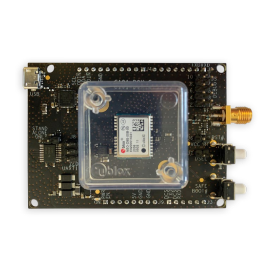
2 C101-D9S product overview 2.1 Components C101-D9S houses the NEO-D9S L-band correction data receiver. The board is powered from the USB cable connection or via Arduino shield. The main components of the board are listed below and shown in Figure 1 and Figure 2: •... -
Page 6: Jumpers
• J8: This jumper switches the communication from the UART2 of the NEO-D9S to the J2 or J3 connector of the Arduino shield (refer to Appendix D for further details). Figure 3: C101-D9S jumpers overview For further details, see the C101-D9S schematic in Appendix D. UBX-20031865 - R02 C101-D9S product overview... -
Page 7: C101-D9S Standalone Operation
C101-D9S - User guide C101-D9S standalone operation This section provides some quicksteps to enable NEO-D9S standalone operation, and connecting via u-center (see u-center user guide [3]). • Connect the supplied L-band antenna to the RF SMA connector. Ensure good visibility of the GEO communication satellites. - Page 8 C101-D9S - User guide Figure 6: UBX-MON-VER message NEO-D9S needs to be properly configured to receive the L-band signal correction data. See Appendix B for the default NEO-D9S L-band configuration, which can be adapted for other services. The messages UBX-MON-PMP and UBX-RXM-PMP (see Figure 7 and Figure 8) can be polled or enabled to check respectively the reception of the signal and the decoded correction data.
-
Page 9: C101-D9S Operation With C099-F9P
C101-D9S - User guide C101-D9S operation with C099-F9P It is possible to use the C101-D9S board together with C099-F9P. Figure 9 shows how to interface the C101-D9S board with the C099-F9P board. Figure 9: C101-D9S - C099-F9P interfacing scheme Figure 10 shows the placement of the Arduino connectors on the C101-D9S board and Figure shows how to physically connect the C099-F9P board to the C101-D9S board via the Arduino shield. - Page 10 C101-D9S - User guide Figure 11: Connecting C101-D9S to C099-F9P Depending on the position of jumper J8 on the C101-D9S board (as shown below) the ZED-F9P housed on the C099-F9P board will receive the correction data on the UART1 or the UART2 port:...
-
Page 11: Appendix
C101-D9S - User guide Appendix A Glossary Abbreviation Definition FTDI Future Technology Device International Geostationary Earth Orbit Light Emitting Diode Low Noise Amplifier Radio Frequency RHCP Right Hand Circular Polarized SubMiniature version A UART Universal Asynchronous Receiver Transmitter Universal Serial Bus... -
Page 12: D C101-D9S Schematics
C101-D9S - User guide See the NEO-D9S Integration manual [1] for further details. D C101-D9S schematics The following pages show the complete schematics for the C101-D9S evaluation board. UBX-20031865 - R02 Appendix Page 12 of 16 C1-Public... - Page 13 C101-D9S - User guide UBX-20031865 - R02 Appendix Page 13 of 16 C1-Public...
- Page 14 C101-D9S - User guide UBX-20031865 - R02 Appendix Page 14 of 16 C1-Public...
-
Page 15: Related Documentation
For product change notifications and regular updates of u-blox documentation, register on our website, www.u-blox.com. Revision history Revision Date Name Comments 30-Jul-2020 dama Initial release 24-June-2021 dama Add chapter 4: C101-D9S operation with C099-F9P UBX-20031865 - R02 Related documentation Page 15 of 16 C1-Public... -
Page 16: Contact
C101-D9S - User guide Contact For complete contact information, visit us at www.u-blox.com. u-blox Offices North, Central and South America Headquarters Asia, Australia, Pacific Europe, Middle East, Africa u-blox America, Inc. u-blox Singapore Pte. Ltd. u-blox AG Phone: +1 703 483 3180...
Need help?
Do you have a question about the C101-D9S and is the answer not in the manual?
Questions and answers