Table of Contents
Advertisement
Quick Links
Advertisement
Table of Contents

Related Manuals for Rice Lake SP2200


Summary of Contents for Rice Lake SP2200
- Page 1 SP2200 Ticket Printer Software Version 1.2 Installation Manual 34171...
-
Page 2: Table Of Contents
Demand/Continuous Mode ...................... 18 4.1.3 Test Mode ..........................19 4.1.4 Switch Module ......................... 19 Copyright © 1999 Rice Lake Weighing Systems. All rights reserved. Printed in the United States of America. Specifications subject to change without notice. Version 1.2, June 1999... - Page 3 Stopping ID Code Incrementing ....................27 Setting the Number of Line Feeds between Print Requests ..........27 Switch Module Command Summary ..................27 SP2200 Control Codes and Escape Sequences ..............28 SP2200 Control Codes ......................29 ASCII Character Set ....................... 30 Printer Maintenance .......................
-
Page 4: About This Manual
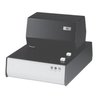
These procedures are to be performed by qualified service personnel only. 1.0 Introduction The SP2200 Ticket Printer is a bidirectional dot matrix printer designed for use in electronic weighing, point- of-sale, and industrial applications. The SP2200 is available in 115 VAC, and 230 VAC models. -
Page 5: Self-Test And Monitor Mode
Request printing using the PRINT button on the SP2200 switch module 1.2.5 Time and Date The time and date option provides time and date stamping for tickets printed by the SP2200. The time and date module can be programmed using the optional switch module or a serial sending device. -
Page 6: Installation And Setup
Section 2.3 to verify installation. Setup Initial setup of the SP2200 consists of installing the print ribbon, setting the head gap, and running the printer self-test. See Section 2.4 for information about installing optional equipment. - Page 7 Hole for cone-shaped tab on back of ribbon cartridge Ribbon drive gear Figure 2-2. SP2200 print mechanism, showing ribbon drive gear 3. Snap the cartridge into place, fitting the hole in the ribbon take-up knob over the ribbon drive gear. If necessary, adjust the ribbon take-up knob to align the cartridge gear with the ribbon drive gear.
-
Page 8: Setting The Head Gap
2.2.2 Setting the Head Gap The SP2200 is designed to accept forms up to a thickness of .024 inches (0.609 mm). The head gap adjust- ment lever (Figure 2-4) can be set to print up to 5-part forms. The six detents allow a head gap range of .004 to .024 inches in .004-inch increments. -
Page 9: Self-Test Procedure
RS-232, 20mA current loop, and RS-422A interfaces. Notes: 1. You must use a separate test plug for each of the interfaces used by the SP2200. A test plug wired for both RS-232 and 20mA current loop will not verify operation of the 20mA circuit. -
Page 10: Installing Optional Equipment
2. Remove 3 screws from back of print mechanism cover (see Figure 2-8). Lift and remove cover. Print mechanism cover screws (3) Electronics cover screw LINE PARALLEL INPUT SERIAL I/O Figure 2-8. Back of SP2200, showing screws for removing electronics and print mechanism covers... - Page 11 Figure 2-9. Bottom view of SP2200, showing screws for removing print mechanism 5. Set the printer upright, then remove the print mechanism. Do not disconnect cables between the print mechanism and the SP2200 circuit board. Replugging cables into the wrong connectors will result in circuit damage.
- Page 12 Serial Port Print Mechanism Ribbon Cable CR10 F R O N T Figure 2-10. SP2200 circuit board, showing locations of optional components and connectors...
-
Page 13: 20Ma Current Loop Interface
2.4.2 20mA Current Loop Interface To install the 20mA current loop interface, disconnect power to the printer and follow the procedure for removing the covers as described in Section 2.4.1. Once the covers are removed, continue with the following steps: 1. -
Page 14: Time And Date Module
Switch module screws (2) Figure 2-11. Bottom of SP2200, showing screws for attaching switch module 2.4.6 Time and Date Module To install the time and date module, disconnect power to the printer and follow the procedure for removing the covers and print mechanism as described in Section 2.4.1. Once the print mechanism is removed, continue with the following steps: 1. -
Page 15: Connecting To Host Devices
Only ASCII-encoded data is supported by the SP2200. The SP2200 can be connected to host devices using other data formats, but a protocol converter must be used to convert the data to ASCII encoding before the SP2200 can process the data. -
Page 16: Serial Port Pin Connections
Serial Port Pin Connections Parallel Port Pin Connections The following table lists the pin connections for The following table lists the pin connections for the the SP2200 serial data input port. SP2200 parallel data input port. Signal Signal Chassis ground... -
Page 17: Iq Plus 310A Indicators
IQ plus 310A Indicators The SP2200 can be connected to the IQ plus 310A indicator at baud rates of 1200 to 19.2 Kbps using either the printer port (RS-232 or 20mA current loop) or the EDP port (RS-232 only). Communications cable connections are made to the J4 terminal block in the 310A as shown in the following tables. -
Page 18: Iq Plus 800/810 Indicators
IQ plus 800/810 Indicators The SP2200 can be connected to the IQ plus 800 and 810 indicators at baud rates of 300 to 19.2 Kbps using either the printer port (RS-232 or 20mA current loop) or the EDP port (RS-232 only). Communications cable connections are made to the J7 terminal block in the indicator as shown in the following tables. -
Page 19: Iq Plus 350 Indicators
IQ plus 350 Indicators The SP2200 can be connected to the IQ plus 350 indicator at baud rates of 300 to 9600 bps. Communications cable connections are made to the terminal blocks in the IQ plus 350 as shown in the following tables. -
Page 20: Iq Plus 510/710 Indicators
IQ plus 510/710 Indicators The SP2200 can be connected to the IQ plus 510 and 710 indicators at baud rates of 300 to 9600 bps. Com- munications cable connections are made to the J4 and J5 terminal blocks in the indicators as shown in the following tables. -
Page 21: Configuring The Sp2200
4.0 Configuring the SP2200 The SP2200 is configured using three banks of DIP switches, labeled S1, S2, and S3, on the back of the unit. Each bank contains 8 switches, numbered 1 through 8. Switches are referred to by bank and switch number;... -
Page 22: Test Mode
3-8 should be set off to prevent accidental changes to the programmed information. This switch has no effect on the use of the PRINT button. Communications Configuration Switches Figure 4-3 shows the DIP switches used to configure communications for the SP2200. These switches are described in the following sections. OFF = 0... -
Page 23: Handshaking
This switch is used for duplex serial communications only. 4.2.4 Toledo Interface Mode Switch 3-2, when set on, enables the Toledo interface mode when connecting the SP2200 to Toledo indicators. This mode allows the SP2200 to communicate with Toledo indicators and to format weight information in both standard and weight extraction modes. -
Page 24: Form Feed
4.3.2 Form Feed Switch 1-7 controls form feed direction. When set on, this switch causes the SP2200 to reverse the feed direction, pulling forms from the rear of the printer toward the front. 4.3.3 Eat <LF> after <CR> Switch 2-1 is used in standard input mode to convert double-spaced data to a single-spaced format. If the host device sends an ASCII carriage return (CR, hex 0D, decimal 13) followed by a line feed (LF, hex 0A, decimal 10), setting this switch on causes the printer to ignore the line feed control code. -
Page 25: Dip Switch Configuration Summary
DIP Switch Configuration Summary The following table summarizes the function of the SP2200 DIP switch banks. See Sections 4-1 through 4-3 for detailed information. c t i & & & & & < > < > & s t i &... -
Page 26: Setting The Time And Date
Setting the Time and Date If the time and date module is installed in the SP2200, you can set the time and date using either the switch module (if installed) or a serial input device such as a PC or ASCII terminal. -
Page 27: Setting Time And Date Using A Serial Command String
4.5.2 Setting Time and Date Using a Serial Command String If you have a PC or ASCII terminal attached to the SP2200, you can set the time and date using a serial command string. The format you use to enter the date and time must match the format set by DIP switch 2-6 (0=International, 1=US format). -
Page 28: Setting Id Codes
Setting ID Codes If the switch module is installed in the SP2200, you can enter ID codes to be printed with weight data when the printer is in weight extraction mode. ID codes must be 8 digits in length and use only the digits 0 through 9 and the following characters: colon, period, and space. -
Page 29: Setting An Incrementing Id Code
Example 2: You can set an ID code to increment from any value entered as a constant ID code. For example, to set the SP2200 to increment through values of 100 to 99999, do the following: 1) Enter the starting value as a constant ID code: Because the starting value is also incremented, you must enter a value of one less than the first value to be printed. -
Page 30: Stopping Id Code Incrementing
You can use the switch module to set the number of line feeds between each print request handled by the SP2200. This function can be used to control spacing and align printing on labels or continuous forms. To set the number of line feeds between prints, set DIP switch 3-8 on to enable the switch module. -
Page 31: Sp2200 Control Codes And Escape Sequences
<ESC> command code followed by the alternate command. For IBM-compatible devices, the escape sequence consists of the key combination for the <ESC> command code (Ctrl-[) followed by a one- character alternate command. The following table lists the alternate command used by the SP2200: Command Command Description... -
Page 32: Sp2200 Control Codes
The following table shows the key combinations used by IBM-compatible devices to enter control codes for the SP2200. The table lists the decimal and hexadecimal values of the control codes, ASCII character desig- nation, and the comand issued to the SP2200 by the control code. -
Page 33: Ascii Character Set
ASCII Character Set " & < >... -
Page 34: Printer Maintenance
Fuse Replacement If the SP2200 will not power on, use the following procedures to check the line fuses, power supply fuse, then the 5 volt supply fuse on the CPU board. 6.3.1 Line Fuses To replace line fuses in the SP2200, do the following: 1. -
Page 35: Ac Power Supply Current Limiting Fuse
6.3.2 AC Power Supply Current Limiting Fuse The SP2200 uses a 5A fuse to limit current output of the power supply. If the line fuses are good but the SP2200 does not power up when connected to the power source, use the following procedure to check the power supply fuse: 1. - Page 36 Table 6-2. Selected SP2200 Replacement Parts, Electronics and Print Mechanism...
-
Page 37: Sp2200 Specifications
7.0 SP2200 Specifications Electrical Specifications Voltage: 115 or 230 VAC (–10% / +15%) Frequency: 50 or 60 Hz Fusing: Two 1.25A Slo-Blo (UL/CSA) 3AG @ 115 VAC operation, or Two 0.75A Slo-Blo (UL/CSA) 3AG @ 230 VAC operation One 125V/5.0A fast-acting, socketed (UL/CSA) microfuse One 2.0A fast-acting, socketed (UL/CSA) microfuse... -
Page 38: Sp2200 Limited Warranty
SP2200 Limited Warranty Rice Lake Weighing Systems (RLWS) warrants that all RLWS equipment and systems properly installed by a Distributor or Original Equipment Manufacturer (OEM) will operate per written specifications as confirmed by the Distributor/OEM and accepted by RLWS. All systems and components are warranted against defects in materials and workmanship for one (1) year.
Need help?
Do you have a question about the SP2200 and is the answer not in the manual?
Questions and answers