Table of Contents
Advertisement
Quick Links
Advertisement
Chapters
Table of Contents

Subscribe to Our Youtube Channel
Related Manuals for Rice Lake 5000 Series


Summary of Contents for Rice Lake 5000 Series
- Page 1 Swecoin Kiosk Printer 5000 Series Models Installation & Operation Manuals 72056...
- Page 2 TTP 5200/5250 Kiosk Printer Sub-system Installation Manual Publ. No. 01436-000, Ed. C...
-
Page 3: Table Of Contents
CONTENTS INTRODUCTION ......................3 About this manual................. 3 Updating ....................3 PRODUCT PRESENTATION..................4 Printer exterior ..................4 Differences between TTP 5200/5250 and TTP 5000/TTP 5100 ..4 SUMMARY OF CONTROL CODES & ESCAPE SEQUENCES ........ 5 Character and bit-image graphics mode commands ......5 Label and other top-of-form oriented commands ......... - Page 4 REVISION HISTORY Edition C, major changes • Command ESC C n1 n2 (Set page length, portrait mode) Illustration corrected. • Command ESC a n1 n2 (Set page width, landscape mode): Illustration corrected. Edition B, major changes • Command ESC a n1 n2 (Set page width, landscape mode): Example added. •...
-
Page 5: Introduction
INTRODUCTION About this manual This manual contains the information required for installation and operation of the TTP 5200 and 5250 printers from a host computer such as a PC. NOTE! — The manual also applies to the TTP 5100 printer with the exception of information regarding on-line downloading of firmware, default parameters, character font sets, and logotypes. -
Page 6: Product Presentation
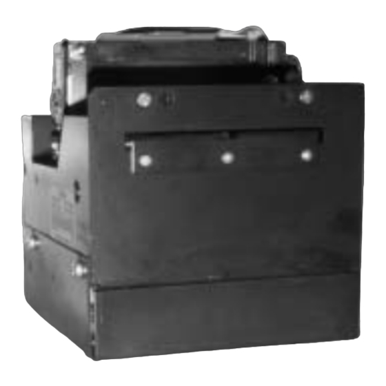
PRODUCT PRESENTATION Printer exterior Figure 1. Printer exterior Differences between TTP 5200/5250 and TTP 5000/TTP 5100 The main differences between the TTP 52xx and the previous TTP 5000 and TTP 5100 models are • the type of memory component used for storing the firmware on the control board. The EPROM used in the TTP 5000 and TTP 5100 models is replaced with a flash PROM that permits downloading of firmware, default parameters, up to 8 character font sets, and logotypes. -
Page 7: Summary Of Control Codes & Escape Sequences
SUMMARY OF CONTROL CODES & ESCAPE SEQUENCES COMMANDS NOT TO BE USED! The printer uses the following commands for internal house-keeping purposes. These commands must not be used for application programming. ESC 4BH ESC 57H ESC ENQ FEH ESC ECQ FFH Commands marked cannot be used with the TTP 5100. - Page 8 Code Decimal* Function Page Remark ESC & 4 1B 26 04 27 38 4 Store current parameter values in TTP 5100 flash PROM ESC & C 1B 26 43 27 38 67 Erase all character sets TTP 5100 ESC & D 1B 26 44 27 38 68 Erase character sets 4—7...
- Page 9 Code Decimal* Function Page Remark ESC SI 1B 0F 27 15 Reset from double-height print mode ESC SO 1B 0E 27 14 Set double-height print mode ESC T n 1B 54 n 27 84 n Reversed print mode on/off ESC W 1B 57 27 87 Windows mode on/off...
-
Page 10: Label And Other Top-Of-Form Oriented Commands
Label and other top-of-form oriented commands Code Decimal Function Page ESC A n1n2n3 1B 41 n1n2n3 27 65 n1n2n3 Set label (block) length ESC BC b1 1B 42 43 b11 27 66 67 b1 Clear bar code field ESC BS b1...b11 1B 42 53 b1...b11 27 66 83 b1...b11 Reserve bar code field... -
Page 11: Software Command Syntax
SOFTWARE COMMAND SYNTAX Character- and bit-image graphics commands Horizontal Tabulation (09H), (9) decimal Shifts the current print position to the next character Tab position. Refer to the ESC + F +n1..nx command on page 21. Line Feed (0AH), (10) decimal Prints the data in the input buffer in the current character mode (such as double height and double width) and adds a line space as specified by the line spacing setting (see command ESC + 3 n on page 16). - Page 12 Form Feed (0CH), (12) decimal Prints data from the input buffer and feeds the paper to the top of the next page. The FF command default value is as defined in the Start-up Parameter setting, n14, n15 and/or n37. In Landscape mode (ESC+!+n, bit 3 = 1), print is effected by the FF command. In TOF mode, the printer interprets incoming FF commands as ESC + X + 08 + 00 If Autocut is set = 1 , FF effects Form Feed, Cut and Eject.
- Page 13 Clear presenter (05H), (5) decimal Used to clear the paper path in the presenter module, for example, to fully eject a document that was not removed after previous print, cut, and eject operation. Partly printed documents will be cut and ejected. Unsuccessful execution of this command (presenter sensor still detects paper in the presenter) results in the printer setting bit 1 of the status response byte 2, to a ”1”.
- Page 14 ESC + ! + n Select character set and character parameters (1BH)+(21H)+n, (27)+(33)+n decimal This command sets and/or removes a selection of character-related parameters. Bits 3—7 apply to all character sets. Character set No. 0 is the basic (default) set. NOTE! —...
- Page 15 NOTE! — Printout in landscape mode is effected with the FF command. NOTE! — If more than 240 characters are sent to the printer before an LF, an automatic print-out of the first part of the line buffer contents is effected. This print-out is made with the character parameter status as known to the printer at the time.
- Page 16 ESC + & + NUL Download character set (1BH)+(26H)+(00H) ..., (27)+(38)+(0) decimal This command is used to download a character set. The character set is placed in the first free address position in the order of download sequence. A downloadable character set consists of a header containing data describing the set as well as data for each individual character in the set.
- Page 17 ESC + & + 4 Store current parameter values in flash PROM (1BH)+(26H)+(04H), (27)+(38)+(4) decimal Stores all parameter values, currently in use in the printer, as permanent default parameter values in the flash PROM. This takes approximately 15 seconds. The printer then resets automatically and activates the presenter motor temporarily.
- Page 18 ESC + 3 + n Set line spacing (1BH)+(33H)+n, (27)+(51)+n decimal The default line spacing is directly related to the size of the selected font. Examples: 10 cpi 30 pixels = 3.75 mm 12 cpi 24 pixels = 3.0 mm 15 cpi 20 pixels = 2.5 mm 17 cpi...
- Page 19 ESC+a+n1+n2 Set page width (landscape mode) (1BH)+(61H)+n1+n2, (27)+(97)+n1+n2 decimal Paper transport direction Page width (minimum 75 mm) Page length = applicable print window width SW97062-R2 Figure 2. Definition of page length in landscape mode The command sets the page width, expressed as a number of 0.125 mm pixel line feeds. The command has to be applied in character print mode.
- Page 20 ESC+C+n1+n2 Set page length (portrait mode) (1BH)+(43H)+n1+n2, (27)+(67)+n1+n2 decimal Paper transport direction Page length (minimum 75 mm) Page width = applicable print window width SW97063-R2 Figure 3. Definition of page length in portrait mode Sets the page length expressed as a number of 0.125 mm pixel line feeds. The command shall be applied in character print mode.
- Page 21 ESC+d+n Execute n line feeds (1BH)+(64H)+n, (27)+(100)+n decimal Executes the number of line feeds as defined by variable n. The length of each line feed is determined by • the default value for selected character font (see page 16) or •...
- Page 22 ESC + ENQ + 3 Parameter setting data enquiry (1BH)+(05H)+(03H), (27)+(5)+(3) decimal This command can be used with all TTP 5xxx models connected through the serial interface. Requests 41 bytes of information about the current parameter settings, that is, the default parameters stored in flash PROM (see Section 5.3 on page 43) or any parameter value temporarily set by other ESC commands/.
- Page 23 ESC + ENQ + 7 Program version enquiry (1BH)+(05H)+(06H), (27)+(5)+(7) decimal This command can be used with all TTP 5xxx models connected through the serial interface. Requests 2-byte information about the installed firmware version. ESC + ENQ + 8 Presenter clear enquiry (IBH)+(05H)+(8), (27)+(5)+(8) decimal Requests status from the presenter sensor.
- Page 24 ESC + FF + n Eject only (1BH)+(0CH)+n, (27)+(12)+n decimal To be used following an ESC + RS command. ESC+FF+n effects ejection through the presenter module of a previously cut-off document. Variable n represents the number of eject steps, each of approximately 2 mm length. The maximum number of steps is 255. The primary use of this command is to eject a document only partially (partly retained in the presenter module).
- Page 25 ESC + h + n Set multiple-height print mode (1BH)+(68H)+n, (27)+(104)+n decimal NOTE! — This command is active only in double height mode set with the ESC + SO command. The ESC + h + n command stays active as long as the printer remains in the ”Double Height”...
- Page 26 ESC + O + n1 + n2 Absolute line positioning (1BH)+(4FH)+n1+n2, (27)+(79)+n1+n2 decimal Moves the paper forward to the specified pixel line position. ESC + q + n Burn time adjustment (1BH)+(71H)+n, (27)+(113)+n decimal Value n represents the ON time of the thermal head resistors. This command adjusts the burn time to get optimal print contrast for the paper quality in use.
- Page 27 ESC + RS Cut paper (1BH) + (1EH), (27) + (30) decimal Effects paper cut-off only. No eject function even when such feature is present. If the document produced so far is less than 75 mm, the paper will automatically be advanced to 75 mm total length before being cut.
- Page 28 ESC + SI Reset from double-height mode (1BH)+(0FH), (27)+(15) decimal Resets the printer to normal mode from double height mode (selected with command ESC + SO). The ESC+SI command is valid only in double-height mode. NOTE! — If more than 240 characters are sent to the printer before an LF, an automatic print-out of the first part of the line buffer takes place.
-
Page 29: Label- And Other Top-Of-Form Oriented Commands
ESC + W Windows mode ON/OFF (1BH)+(57H), (27)+(87) decimal Sets the printer into Windows mode. At repeat of the command, the printer exits from the Windows mode. This command is only used by the TTP5X00 Windows drivers and should not be used in other contexts. - Page 30 ESC+A+n1+n2+n3 Set label (block) length (1BH)+(41H)+n1+n2+n3, (27)+(65)+n1+n2+n3 decimal Determines the length of the label block to be printed. The printer control board has approximately 50 K bytes of page memory available for data storage. With this page memory, the maximum available block length (lmax.) is 600 pixel lines, equal to approximately 75 mm paper length in the 80 mm wide mechanism.
- Page 31 ESC+BS+b1+b2+...+b11 Reserve bar code field (1BH)+(42H)+(53H)+b1+b2+...+b11, (27)+(66)+(83)+b1+b2+...+b11 decimal Bar codes can only be printed in portrait mode. The command reserves an information field as a bar code field. The command also identifies the type, number of digits, and the configuration of bars to be placed in the bar code field.
- Page 32 Specifies the thickness of the narrow bar 0 = 1 pixel 1 = 2 pixels 2 = 3 pixels 3 = N/A 4 = 5 pixels 5 = 6 pixels 6 = 7 pixels 7 = 8 pixels All other values are invalid. Specifies the wide-bar-to-narrow-bar ratio.
- Page 33 ESC+DC+d1 Clear comment field (1BH)+(44H)+(43H)+d1, (27)+(68)+(67)+d1 decimal Clears the comment field reserved by the ESC+DS command. Specifies the comment field to be cleared (0—15). Comment fields can be specified in any sequence but other values than 0—15 are ignored. Of command codes specified before this command, only ESC+T+n, (reversed printing) remains in effect after execution of ESC+DC+d1.
- Page 34 Character type Character type Orientation, 0 = Portrait, 1 = Landscape Not used 5,4,3 Determine height of characters. 8 different heights (0—7) can be selected 2,1,0 Determine width of characters. 8 different widths (0—7) can be selected No more than one orientation and one type of character can appear in the same comment field.
- Page 35 ESC+DW+d1+d2...+NUL State comment field data (1BH)+(44H)+(57H)+d1+d2...+(00H), (27)+(68)+(87)+d1+d2...+0 decimal Fills comment field reserved by the ESC+DS command with comment data. Specifies comment field No. (0—15) that may be specified in any sequence. d1 values other than 0—15 are ignored d2... Specifies comment data byte(s). Must be placed at the end of the comment data.
- Page 36 ESC+GS+g1+g2+...+g8 Reserve graphics field (1BH)+(47H)+(43H)+g1+g2+...+g8, (27)+(71)+(67)+g1+g2+...+g8 decimal Reserves a graphics field within a label block defined with command ESC+A+n1+n2. The ESC+GS command also defines the size of the graphics field. Specifies graphics field No. (0—15). Graphics fields may be specified in any order, but values other than 0—15 are ignored.
- Page 37 ESC+GW+g1+g2+...+gn State graphics data (1BH)+(47H)+(57H)+g1+g2+...+gn, (27)+(71)+(87)+g1+g2+...+gn decimal Fills the graphics field reserved by the ESC+GS with graphics data. Specifies graphics field No. (0—15) in any order. Other values than 0—15 are ignored. g2...gn Specifies graphics data bytes. Number of data bytes g2..gn: (number of bytes in X direction multiplied by number of lines in Y direction) All character and control codes are invalid.
- Page 38 l2l3 Specifies X co-ordinate for the ruler line origin (l2 is the higher-order and l3 the lower-order byte). l2 and l3 must be 1-byte hexadecimal or decimal numbers. The value specified by l2 and l3 must not exceed the total pixel count that can be handled by the printer.
- Page 39 ESC + M+n1+n2 Top-of-form definition (1BH)+(4DH)+n1+n2, (27)+(77)+n1+n2 decimal This command specifies maximum (n1) and minimum (n2) length of the TOF (Top-of- Form) mark printed reverse side of the paper. The TOF mark identifies the top of the next form (document). The length of the mark is expressed in pixel lines of 0.125 mm height. Active transition is from ”black”...
- Page 40 ESC + x + n1 + n2 Set internal TOF counter at 256*n1+n2 (1BH)+(78H)+n1+n2, (27)+(120)+n1+n2 decimal Presets an internal counter to value 256 x (n1+n2) corresponding to a number of pixel line feeds. At completed printout, an ESC + Z command effects paper feed until a TOF mark is detected, that is, when black-to-white transition is detected at the trailing edge of the TOF mark.
-
Page 41: Downloadable Character Sets, Logotypes And Firmware
DOWNLOADABLE CHARACTER SETS, LOGOTYPES AND FIRMWARE User-defined character set Refer to software command ESC & NUL and figures on the next page. New character sets can be downloaded sequentially using the ESC & NUL command. A downloaded character set consists of a header containing data describing the font as well as data for every character in the set. - Page 42 Char_width Char_width Char_width Char_width Char_Ystart Char_Yheight Char_sizeY Baseline Char_sizeX Char_pitch Char_pitch Char_pitch Character bitmap data: A character is made up of a bitmap the size of which is: Char_sizeX * Char_Yheight bytes. COLUMN Col 0 Col 1 Col 2 LSB MSB Row 1 =03H =FFH...
-
Page 43: User-Defined Logotype
time, any data sent to the printer will be lost. NOTE ! — Download is finalized by an internal reset visible by the presenter motor being driven momentarily. CAUTION! — Downloading to the flash PROM will erase the RAM completely since the RAM is used during the downloading process. - Page 44 The memory used to store logotypes is not automatically cleared. All logotypes can be cleared with the ESC & L command. Logotype printing: The logotype print command is ESC + g + n1..n5 where n1..n5 determine which logotype to print and its print position. One byte logotype number, (0—15) n2n3 Two byte X position measured in pixels from the left hand edge of the print...
-
Page 45: Default Parameters
Default parameters A number of bytes, currently 41, in the flash PROM hold various parameter values called default parameters. One or several of them can be overridden temporarily with the command ESC+&+2+n1...n41. All 41 bytes have to be sent, even if only some of the values need to be modified. - Page 46 TOF mark maximum Black mark size as defined by ESC+M+n1+n2 TOF mark minimum Black mark size as defined by ESC+M+n1+n2 Burn time 1—15 as defined in the ESC + q + n command CR function (EOL) 0 = CR/LF (Swecoin emulation), 1 = CR (default) Portrait page length n1 As defined in the ESC + C + n1 + n2 command Portrait page length n2...
- Page 47 NOTE 1! — The time required for the printer to process the default parameter data downloaded from the host is, typically, 15 seconds (max. 20 seconds). Any data sent to the printer during this time will be lost. NOTE 2! — Self-test printout will show the default parameter values stored in flash PROM.
-
Page 48: Firmware Loading
Firmware loading 5.4.1 Introduction CAUTION! — Loading new firmware into the flash PROM will erase the RAM completely since the RAM is used during the loading process. Any print data residing in RAM will be lost. The TTP 52xx firmware is stored in a 128 Kbyte flash PROM (AMD 29F010). This device is divided into 8 sectors, each of 16 Kbyte that can be separately erased and reprogrammed. -
Page 49: Loading Procedure
CAUTION! — When you load the hex file into the printer, previously downloaded logotypes, and any print data residing in RAM, will be lost and have to be reloaded. Previously installed character sets remain unchanged. Firmware loading also sets ALL parameters to the factory default values. -
Page 50: Status Responses
STATUS RESPONSES TTP 5000 compatible status response commands The commands described in this section can be used with all TTP 5XXX models. Sending an ENQ (05H) Clear Presenter or an ESC ENQ 1 (1BH 05H 01H) Status Enquiry to the printer, results in the printer sending a status report to the host computer. This status report reflects the status of the available sensors in the printer system and identifies possible error conditions. -
Page 51: Additional Status Response Command For Ttp 5200/5250
Additional status response command for TTP 5200/5250 Refer to software command ESC ENQ 6 (see page 20). When the above command is received, the printer will respond with 2 bytes reflecting the status of the printer sensors and possible error conditions. Bit value = 0 (zero) indicates that there is no error Bit value = 1 (one) indicates an error, such as paper near end or paper end Byte 1:... -
Page 52: Power-On Test
POWER-ON TEST If a power interruption occurs while printer parameters are being downloaded to the flash PROM, there is minor risk that some parameter might be incorrectly stored. At power-ON, a test will check the parameters for consistency by performing a checksum comparison. If a checksum error is found, bit 7 of the first byte in the Status Enquiry response is set to value 1. -
Page 53: Serial Interface
SERIAL INTERFACE The control board is equipped with a 10-pole ribbon cable type connector. The pinout of this connector is designed to mate with a standard D-sub 9-pole male connector through a straight ribbon cable accessory (SWC602-200). The pinouts of the 10-pole connector and the 9-pin D-sub connector are shown in the following table: Pin No. - Page 54 Figure 5. Serial interface adapter cable SWC602-200 (accessory) Printer 10-p. 9-p. D-sub Signal Signal 25-p. D-sub 9-p. D-sub NOTE ! — Pins 4 and 7 on the 10-pin connector are connected by a jumper. This allows handshaking using either DTR/DSR and/or RTS/CTS signals. TTP 5200/5250 Kiosk Printer Sub-system –...
-
Page 55: Parallel Printer Interface
PARALLEL PRINTER INTERFACE The control board has a 40-pole ribbon cable parallel interface type connector. The printer can be connected to a standard Centronics 36-pole connector using a straight ribbon cable such as the adapter cable SWC601-000 (see figure below). The following table shows the pin assignment in the 40-pole connector: (The table continues on the next page) 40-pole conn. - Page 56 40-pole conn. Centronics Signal Direction Description Frame GND Not connected Not connected Not connected Not connected Not connected Not connected Not connected Figure 6. Parallel interface adapter cable SWC601-000 (accessory) TTP 5200/5250 Kiosk Printer Sub-system – Installation Manual 9911...
-
Page 57: Power Supply
POWER SUPPLY Figure 7. Power supply connector The TTP 5250 has a built-in 5V regulator supplied with 24 VDC. Connector type: 6-pole, female, MOLEX KK, 2.54 mm grid Pole Function Pole Function +5 VDC (TTP 5200 only) +24 VDC +24 VDC The power requirements are as follows: Voltage Print mode... -
Page 58: Printer Dimensions
CAUTION ! The order in which the +5 VDC and +24 VDC are established on the TTP 5200 printer control board is essential. The + 5 VDC must be established before the + 24 VDC drive voltage is brought to the board (and vice versa at power-off). Otherwise, there is a risk of damaging both the printer control board and the thermal print head. - Page 59 Figure 9. Top view. The dimensions in this drawing apply to all basic TTP 52XX models with up to 135 mm paper roll diameter. The paper roll holder, with attached switch button bracket, can be turned symmetrically 180º so that the roll has to be installed from the right hand side of the printer. This also means that the paper feed button, and the connector support bracket for an optional interface adapter cable, will be positioned on the left hand side of the printer.
- Page 60 Figure 10. Top view. TTP 52XX models equipped with the optional paper roll holder for up to 200 mm roll diameter. Figure 11. Top view. TTP 52XX models equipped with the optional paper roll holder for up to 200 mm roll diameter. TTP 5200/5250 Kiosk Printer Sub-system –...
-
Page 61: Basic Character Set
BASIC CHARACTER SET The table below shows the basic characters stored in PROM on the printer control board. The characters in the shaded positions can be substituted with characters from one of several national character sets. See page 60. Hex (1st digit) 112 128 144 160 176 192 208 224 240 Hex. -
Page 62: National Character Sets
NATIONAL CHARACTER SETS This table lists national substitute characters stored in PROM on the printer control board. The position numbers refer to the shaded cells in the table showing the basic character sets. See page 59. The applicable character set is selected with the ESC+R+n command. Pos. -
Page 63: Firmware History
FIRMWARE HISTORY Functions and features are being added from time to time affecting the firmware in the TTP 52xx printers. The following table lists the changes of general interest. Notice that the list may not contain the latest firmware versions. Please visit our web site www.swecoin.se. - Page 64 This page intentionally left blank. TTP 5200/5250 Kiosk Printer Sub-system – Installation Manual 9911...
- Page 65 TTP 5100/5200/5250 Kiosk Printer Sub-system Operating Instructions Publ. No. 38-1081-00, Ed. B...
- Page 66 Contents 1 INTRODUCTION......................3 1.1 About this manual ..................3 1.2 Updating ....................3 1.3 Safety precautions ..................3 2 PRODUCT PRESENTATION..................4 3 LOADING THE PAPER....................5 3.1 Removing remaining paper and core ............5 3.2 Loading new paper roll................6 4 REMOVING PAPER JAM ...................
- Page 67 STANDARDS, LICENSES, ETC. Safety standard IEC950 certified, EN50082-1 EMC / EMI EN55022/B, EN50082-1, prEN50082-2 The TTP 5100 and TTP 52xx printers comply with the EMC directives for CE marking. FCC COMPLIANCE STATEMENT This equipment has been tested and found to comply with the limits for a Class A digital device, pursuant to part 15 of the FCC Rules.
-
Page 68: Introduction
INTRODUCTION About this manual This document describes the daily handling of the TTP 5100, TTP 5200, and TTP 5250 printers. Since the behavior of the printer to a large extent depends on the design of the application software, please also refer to the applicable system documentation. Updating This manual will be updated from time to time as printer functions and features are added or amended. -
Page 69: Product Presentation
PRODUCT PRESENTATION Figure 1. Printer exterior TTP 5100/5200/5250 Kiosk Printer Sub-systems - Operating Instructions Edition B, May 97... -
Page 70: Loading The Paper
LOADING THE PAPER Removing remaining paper and core If there is any paper left in the printer, proceed as follows: 1. Lower the paper release lever to horizontal position. Remove any remaining pieces of paper. 2. Pull out the paper rearwards and remove the core from the paper roll support shaft. If necessary, clean the paper path by blowing or wiping with a soft brush. -
Page 71: Loading New Paper Roll
Loading new paper roll 1. Turn the paper roll as shown. The paper should be inserted into the printer with the temperature sensitive side up. Figure 4. Turn the paper roll with the temperature-sensitive side up Tear off approximately 0.5 m from the new paper roll. CAUTION! This is important since the outer end of the paper is usually fixed to the roll with some type of glue or self-adhesive substance that might otherwise cause paper jam... - Page 72 3. Raise the paper release lever to vertical position. 4. Turn the paper roll as shown and insert the edge of the paper into the back of the print module. Note that the paper should pass beneath a plastic bar (see arrow). Figure 6.
-
Page 73: Removing Paper Jam
REMOVING PAPER JAM CAUTION! — If a paper jam has occurred, pull the paper out forwards (in the paper-feed direction). Pulling a curled or wrinkled paper backwards can damage the print mechanism. If paper jam has occurred between the cutter module and the print module, use one of the following procedures to remove the jam: 1. -
Page 74: Fault Finding
FAULT FINDING Symptom Suggested actions • Nothing is printed but the document Verify that the paper roll is turned the with becomes cut and ejected. the temperature-sensitive side up. See Section 3.2. • Verify that the paper used meets the paper specification. - Page 75 This page intentionally left blank. TTP 5100/5200/5250 Kiosk Printer Sub-systems - Operating Instructions Edition B, May 97...
Need help?
Do you have a question about the 5000 Series and is the answer not in the manual?
Questions and answers