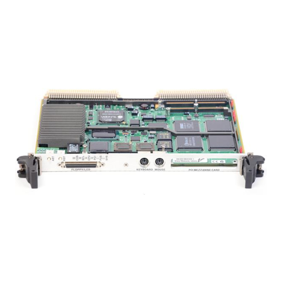
Motorola MVME2600 Series Installation And Use Manual
Hide thumbs
Also See for MVME2600 Series:
- Reference manual (283 pages) ,
- Installation and use manual (198 pages) ,
- Programmer's reference manual (20 pages)
Advertisement
Quick Links
Advertisement

Summary of Contents for Motorola MVME2600 Series
- Page 1 MVME2600 Series Single Board Computer Installation and Use V2600A/IH2...
- Page 2 Motorola, Inc. assumes no liability resulting from any omissions in this document, or from the use of the information obtained therein. Motorola reserves the right to revise this document and to make changes from time to time in the content hereof without obligation of Motorola to notify any person of such revision or changes.
- Page 3 Motorola symbol are registered trademarks of Motorola, Inc. AIXª is a trademark of IBM Corp. PowerPCª is a trademark of IBM Corp. and is used by Motorola with permission. All other products mentioned in this document are trademarks or registered trademarks of their respective holders.
- Page 4 Motorola, Inc. assumes no liability for the customer's failure to comply with these requirements. The safety precautions listed below represent warnings of certain dangers of which Motorola is aware. You, as the user of the product, should follow these warnings and all other safety precautions necessary for the safe operation of the equipment in your operating environment.
- Page 5 All Motorola PWBs (printed wiring boards) are manufactured by UL-recognized manufacturers, with a ßammability rating of 94V-0. This equipment generates, uses, and can radiate electro- magnetic energy. It may cause or be susceptible to electro-magnetic interference (EMI) if not installed and WARNING used in a cabinet with adequate EMI protection.
- Page 7 Contents Chapter 1 Hardware Preparation and Installation Introduction ......................1-1 Equipment Required....................1-3 Overview of Startup Procedure .................1-4 Unpacking Instructions ..................1-5 Hardware ConÞguration..................1-5 MVME2603/2604 Base Board Preparation ............1-6 Cache Mode Control (J3) ................1-7 Flash Bank Selection (J10)................1-7 Serial Port 4 Receive Clock ConÞguration (J16) ........1-9 Serial Port 4 Transmit Clock ConÞguration (J17) ........
- Page 8 Chapter 2 Operating Instructions Introduction ......................2-1 Applying Power ....................2-1 ABORT Switch (S1) ..................2-2 RESET Switch (S2) ..................2-3 Front Panel Indicators (DS1 - DS6) ............. 2-4 Memory Maps ...................... 2-5 Processor Memory Map................2-5 Default Processor Memory Map 2-5 PCI Local Bus Memory Map................
- Page 9 Real-Time Clock/NVRAM/Timer Function ...........3-13 Programmable Timers.................3-14 Interval Timers 3-14 16-Bit Timers 3-15 Serial Communications Interface ..............3-15 Z8536 CIO Device 3-16 Base Module Feature Register ..............3-16 P2 Signal Multiplexing................3-17 ABORT Switch (S1)..................3-18 RESET Switch (S2) ..................3-19 Front Panel Indicators (DS1 - DS6)............3-19 Polyswitches (Resettable Fuses) ..............3-20...
- Page 10 CNFG - ConÞgure Board Information Block ........... 6-2 ENV - Set Environment..................6-3 ConÞguring the PPCBug Parameters ............6-3 ConÞguring the VMEbus Interface............6-12 Motorola Computer Group Documents ............A-1 ManufacturersÕ Documents ................A-2 Related SpeciÞcations..................A-6 Appendix B Specifications SpeciÞcations ......................B-1...
- Page 11 Interface Characteristics................C-8 Proper Grounding ....................C-9 Appendix D Troubleshooting CPU Boards: Solving Startup Problems Introduction ......................D-1 Glossary Abbreviations, Acronyms, and Terms to Know........... GL-1...
- Page 13 Figures Figure 1-1. MVME2603/2604 Base Board Block Diagram......1-2 Figure 1-2. MVME2603/2604 Switches, Headers, Connectors, Fuses, LEDs ......................1-10 Figure 1-3. MVME712M Connector and Header Locations ......1-16 Figure 1-4. J15 Clock Line ConÞguration............1-17 Figure 1-5. MVME712M Serial Port 1 DCE/DTE ConÞguration ....1-18 Figure 1-6.
- Page 15 Tables Table 1-1. VMEmodule/Transition Module Correspondence .......1-3 Table 1-2. Startup Overview ................1-4 Table 1-3. MVME712M Port/Jumper Correspondence ........1-17 Table 2-1. Processor Default View of the Memory Map .........2-6 Table 2-2. PCI Arbitration Assignments............2-9 Table 2-3. IBC DMA Channel Assignments............2-12 Table 2-4. Classes of Reset and Effectiveness ..........2-13 Table 3-1.
- Page 16 Table 5-2. Diagnostic Test Groups..............5-8 Table A-1. Motorola Computer Group Documents ........A-1 Table A-2. ManufacturersÕ Documents ............A-2 Table A-3. Related SpeciÞcations ..............A-6 Table B-1. MVME2603/2604 SpeciÞcations............B-1 Table C-1. EIA-232-D Interconnect Signals............C-3 Table C-2. EIA-232-D Interface Transmitter Characteristics ......
- Page 17 1Hardware Preparation and Installation Introduction This manual provides general information, hardware preparation and installation instructions, operating instructions, and a functional description of the MVME2603/2604 family of Single Board Computers. The MVME2603/2604 is a single-slot VMEmodule equipped with a PowerPCª Series microprocessor. The MVME2603 is equipped with a PowerPC 603 microprocessor;...
- Page 18 Introduction CLOCK DEBUG CONNECTOR MEMORY EXPANSION CONNECTORS GENERATOR L2 CACHE 256K FLASH FLASH 4MB or 8MB PROCESSOR SYSTEM MPC603/604 REGISTERS PHB & MPIC MEMORY CONTROLLER RAVEN ASIC FALCON CHIPSET 33MHz 32/64-BIT PCI LOCAL BUS ETHERNET SCSI VME BRIDGE W83C553 DEC21140 53C825A UNIVERSE REGISTERS...
- Page 19 Hardware Preparation and Installation Equipment Required The following equipment is required to complete an MVME2603/ 2604 system: VME system enclosure System console terminal Operating system (and/or application software) Disk drives (and/or other I/O) and controllers Transition module (MVME712M or MVME761) and connecting cables MVME2603/2604 VMEmodules are factory-configured for I/O handling via either MVME712M or MVME761 transition modules.
- Page 20 Overview of Startup Procedure In models of the MVME2603/2604 that are configured for MVME712M I/O mode, the pin assignments of VMEbus connector P2 are fully compatible with other transition modules of the MVME712 series. In MVME761-compatible models, certain signals are multiplexed through P2 for additional I/O capacity. Refer to Signal Multiplexing in Chapter 3 for details.


Need help?
Do you have a question about the MVME2600 Series and is the answer not in the manual?
Questions and answers