Table of Contents
Advertisement
Advertisement
Table of Contents

Related Manuals for Cantel Medical MEDIVATORS DSD EDGE


Summary of Contents for Cantel Medical MEDIVATORS DSD EDGE
- Page 1 Service Manual System Version 5.65...
- Page 2 MEDIVATORS , DSD EDGE , RAPICIDE , and ACTRIL are registered trademarks of Medivators Inc. ® ® ® ® PENTAX is a registered trademark of Hoya Corporation. ® OLYMPUS is a registered trademark of Olympus Corporation. ® FUJIFILM is a trademark of FUJIFILM Corporation. KARL STORZ is a registered trademark of Karl Storz GmbH &...
-
Page 3: Table Of Contents
TABLE OF CONTENTS Chapter 1 - INTRODUCTION Using this Manual ..........................5 Indication for Use ........................5 Safety .............................. 6 Intended Use ..........................6 Operator Safety ......................... 6 Moving the DSD EDGE Endoscope Reprocessor ............... 6 ® Installation and Maintenance ..................... 7 Water Quality and Filtration ....................... - Page 4 Chapter 5 - OPERATION Introduction ........................... 85 Cycle Operation ..........................86 Startup Phase ..........................86 Flush Phase ..........................86 Wash Phase ..........................87 Air Phase ..........................88 Pre-start Inspection ........................88 Disinfecting Endoscopes ....................... 90 Preparing the endoscope ......................90 Leak Testing ..........................
-
Page 5: Chapter 1 - Introduction
An example of each is illustrated below. Indications for Use MEDIVATORS DSD EDGE Endoscope Reprocessing System tests, washes, disinfects and rinses flexible endoscopes, such as fiberoptic and video endoscopes between patient uses. The DSD EDGE Endoscope Reprocessing System is indicated to provide high level disinfection, using RAPICIDE PA High Level Disinfectant, of heat sensitive semi-critical endoscopes. -
Page 6: Safety
Safety This section outlines general safety guidelines for proper operation and service of the reprocessor. Failure to follow these guidelines may result in severe injury or death to the patient and/or operator. Read and understand all operating and service procedures before attempting to operate the reprocessor. If the equipment is not used as specified, the protection by the equipment may be impaired. -
Page 7: Installation And Maintenance
Note: Prior to undertaking any service or maintenance operation, or when resetting the GFI ensure that the DSD EDGE Endscope Reprocessor is disconnected from the ® main power supply. If service or maintenance operations are to be conducted on the water system, ensure that the DSD EDGE Endoscope Reprocessor is isolated from the main water supply. -
Page 8: Chemical
Chemicals The DSD EDGE Endoscope Reprocessor uses RAPICIDE PA Part A and Part B peracetic acid disinfectant components ® ® to high level disinfect endoscopes. Refer to the American National Standard recommended practice titled, Chemical Sterilants and High Level Disinfectants: A guide to Selection and Use (AAMI TIR7:1999) and/or Safe Handling and Biological Decontamination of Reusable Medical Devices in Health Care Facilities and in Nonclinical Settings (AAMI/ ANSI ST35:2003). -
Page 9: Monitoring Disinfectant Potency
Monitoring Disinfectant Potency The disinfectant potency must be verified for each disinfection cycle. Use a peracetic acid test strip to verify that the retained disinfectant sample from the DSD EDGE Endoscope Reprocessor sample port is above the minimum ® recommended concentration (MRC). Endoscope Precleaning and Testing All endoscopes must be manually precleaned prior to disinfection. -
Page 10: Cleaning And Disinfection
Cleaning and Disinfection Always follow established professional guidelines while cleaning and disinfecting endoscopes. The following organizations have published recommended guidelines. Society of Gastroenterology Association for Professionals in Nurses and Associates Infection Control and Epidemiology, Inc. 401 North Michigan Ave. 1275 K Street, NW, Suite 1000 Chicago, IL 60611-4267 Washington, DC 20005-4006 TEL: (800) 245-7462... -
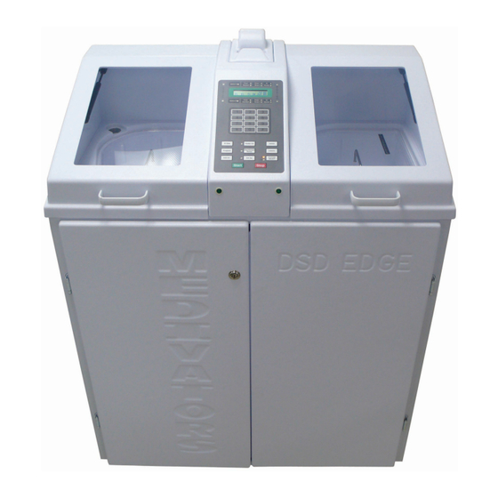
Page 11: Chapter 2 - Installation
Chapter 2 INSTALLATION General This chapter describes the operator controls, and how to set up and program the reprocessor. Station “A” Station “B” Control Panel Control Panel “A” Basin “B” Basin ‘A’ Basin ‘B’ Basin Process Indicators Process Indicators HS 232 RS 232 (for service use only) (for service use only) - Page 12 Endoscope Leak Test Connector Printer Endoscope Hookup connector Disinfectant Sampling Ports Basin Level Sensor Figure 2: DSD EDGE Dual Basin ®...
- Page 13 3/8” NPT Water 1/4” NPT House Connection Compressed Air Connection (optional) 1” NPT Facility drain coupling (right angle hose connector supplied Main power entry module Figure 3: Side and back of DSD EDGE Endoscope Reprocessor ®...
-
Page 14: Supply Supply
System Supply Water Supply For optimum cycle performance, the water supplied to the reprocessor must provide a flow rate of 3.2 gal/min (12 liters/ min), at 35-40 psi (2.4-2.75 bar). A hot and cold water supply requires the use of a tempering valve to maintain a water temperature of 95°C (±4°F) and 35ºC (±2ºC). -
Page 15: System Drain
Warning! This air must be supplied from an oil free air source. System Drain The drain tube provided with the reprocessor consists of 36 inches of 1-inch diameter clear tubing. The drain tube must have 3 inches of drop (7.5 cm) or greater over the 36-inch length. The facility drain should be no higher than 18 inches to provide proper drainage. -
Page 16: Installation Verification
Installation Verification Caution! Operating the 120VAC reprocessor without a hookup fitting might blow the 8-amp slow blow fuse. Operating the 230VAC reprocessor without a hookup fitting might blow the 4-amp slow blow fuse. Refer to the Site Requirements and Installation Guide PN 50097-091. Service: If the reprocessor cannot be verified, contact MEDIVATORS Technical Support at: 1-800-444-4729 or 1-763-553-3300. -
Page 17: Chapter 3 - Operator Control
Chapter 3 OPERATOR CONTROLS General This chapter describes the operator controls, and how to set up and program the reprocessor. -
Page 18: Control Panel
Control Panel The control panel allows the operator to specify settings, view system messages, errors and warnings, and operate the reprocessor. This section describes each function of the control panel. LED Indicators LCD Panel Keypad Function Keys Figure 1 : Control Panel... -
Page 19: Led Indicators
LED Indicators The LED indicators alert the operator to system functions and errors. There are four types of indicators used on the reprocessor control panel. • Status Indicators The status indicators blink if an error occurs, or if the STOP button is pressed. The upper indicator identifies station A. -
Page 20: Lcd Screen
LCD Screen The LCD screen displays system messages and prompts the operator during system setup. • User Prompt displays messages and queries. “A:” represents station A, “B:” represents station B. • Station/Program displays the current operating program. • Program status indicators identify a station as “idle”, “stopped”, “resetting” or “running”. •... -
Page 21: Numeric Keypad
Numeric Keypad The numeric keypad allows the operator to enter numeric information. • The * key can also be used as a “Cancel” or a “Backspace” button. • The # key can also be used as an “Enter” button. Figure 4: Numeric Keypad... -
Page 22: Function Keys
Function Keys The function keys control the operation of the reprocessor. • ID Data Press this button to enter the endoscope identification or serial number, operator ID number, patient ID number, and physician ID number into the log. Each ID entry can contain up to ten digits. This function is only active when the station is idle. - Page 23 Figure 5: Function Keys...
-
Page 24: Setting Up The Reprocessor
Setting Up the Reprocessor Warning! Avoid possible chemical burns. Always wear personal protective equipment (gloves, goggles) when handling disinfectant. Warning! Avoid possible slip injuries. Clean up any spills immediately. Note: Part A Uptake Tube is fitted with the BLUE cap. Part B Uptake Tube is fitted with the WHITE cap. - Page 25 LOAD DISINFECTANT The disinfectant is supplied in two separate 5 liter containers. Part A is the Peracetic Acid component, Part B is the buffer. Both containers fit into the disinfect drawer located on the left hand side of the reprocessor. 1.
- Page 26 SET THE DATE Use this function to set the system date. This setting changes both the control panel display and the internal system clock. 1. Press the SETUP button. 2. Enter 2 on the keypad, then press the ENTER button. 3.
- Page 27 Figure 6: Set Date Screen...
- Page 28 SET THE TIME Use this function to set the system time. This setting changes the display and the internal system clock. Verify the clock setting daily to ensure accuracy. 1. Press the SETUP button. 2. Enter 3 on the keypad, then press the ENTER button. 3.
- Page 29 Figure 7: Set Time Screens...
- Page 30 DISPLAY SOFTWARE VERSION Using the following procedure to view the current version of software installed in the reprocessor. 1. Press the SETUP button. 2. Enter 4 on the keypad, then press the ENTER button. 3. The current software and version is displayed. 4.
- Page 31 Micro controller Flash Code Version Code Version (or “Software” version) Figure 8: Software Version Screen...
- Page 32 DISPLAY LOG This function allows review of the status log on the display. The entire log can be displayed one entry at a time, starting with the most recent entry. 1. Press the SETUP button. • Enter 8 on the keypad, then press the ENTER button. 2.
- Page 33 Figure 9: Display Log Screen and sample entry...
- Page 34 CLEAR LOG The log stores 1463 records per station. Once the log is full, additional records will overwrite the oldest entries. Print a copy of the log and clear the log at regular intervals. 1. Press the STATION SELECT button to choose station A or station B. The selected station must be idle to perform this function.
- Page 35 CLEAR DISINFECTANT CYCLE COUNT Use the following procedure to clear the disinfectant cycle count. 1. Press the STATION SELECT button to choose station A or station B. 2. Press the SETUP button. • Enter 11 on the keypad, then press the ENTER button. 3.
-
Page 36: Water Line Disinfection
Water Line Disinfection This function disinfects the water lines in the reprocessor. The current water quality standard for Washers/Disinfectors in the United States and Canada recommends the use of potable (human consumption/drinking quality) water as the supply water for use in washers/disinfectors. If you facility can supply potable quality water to the DSD EDGE ®... - Page 37 Alcohol Figure 12: Water Line Disinfection Screen Upon completion of a water line disinfection cycle, the on-board .2 micron water filter housing located behind the front access doors should be purged of air. 4. Press the SETUP button. 5. Press 43 on the keypad, then press ENTER. This will open the incoming water supply solenoid valve providing a water supply to the on-board .2 micron filter housing.
-
Page 38: Programming The Reprocessor
Programming the Reprocessor INPUT PROGRAM Custom programs allow the operator to change the cycle parameter settings, or to setup custom reprocessing protocols. A maximum of nine custom programs can be pre-set. Refer to the disinfection cycle chart in the appendix for range settings. - Page 39 6. The “Detergent Inject” screen is displayed. Enter the desired detergent inject time. The volume of detergent is controlled by the number of seconds entered on the screen, up to a maximum of 59 seconds. 1 second = 3 mL detergent solution •...
- Page 40 P1 Flush Set Minutes 00:00 P1 Soak Set Minutes 00:00 P1 Soak Rinse Set Minutes 00:00 Figure 13: Custom Program Setup Screens...
- Page 41 10. The “Alcohol” screen is displayed. Enter the alcohol purge time. • Enter two digits for the minutes, then press ENTER. • Enter two digits for the seconds, then press ENTER. 11. The “Alcohol Inject” screen is displayed. Enter the alcohol inject time. The volume of alcohol is controlled by the number of seconds entered on the screen, up to a maximum of 59 seconds.
- Page 42 P1 Detergent Inject Set Minutes 00:00 Figure 14: Custom Program Setup Screens...
- Page 43 Figure 15: Custom Program Setup Screen...
- Page 44 DISPLAY TEMPERATURES Use the following procedure to view the temperatures. 1. Press the SETUP button. • Enter 13 on the keypad, then press the ENTER button. 2. The temperatures are displayed in Celsius. 3. Press the SETUP button to exit the display. Alcohol Alcohol Basin...
- Page 45 DISPLAY TIME REMAINING Use the following procedure to view the cycle time remaining for both stations. 1. Press the SETUP button. • Enter 17 on the keypad, then press the ENTER button. The typical cycle time remaining for each station is displayed, actual time may vary depending on the rate of incoming water.
- Page 46 DISPLAY STATE TIME A cycle is comprised of a number of states. Use the following procedure to view the state time for both stations. 1. Press the SETUP button. • Enter 18 on the keypad, then press the ENTER button. 2.
- Page 47 PRINT ENTIRE LOG This function prints a copy of the disinfection cycle log. Only the information saved since the last time the log was cleared is printed. Verify the printer is ON before printing. Press the STATION SELECT button to choose station A or station B. 2.
- Page 48 PRINT LAST RUN This function allows printing of a paper copy of the last disinfection cycle run. Verify the printer is ON before printing. Press the STATION SELECT button to choose station A or station B. 2. Press the SETUP button. •...
- Page 49 SET AUTOMATIC PRINTING ENABLE This function prints the log after every disinfection cycle. The default factory setting is “enabled”. Verify the printer is ON before printing. 1. Press the STATION SELECT button to choose station A or station B. 2.
- Page 50 SET DELAYED START DATE/TIME Use the following procedure to program the delayed startup time. 1. Press the STATION SELECT button to choose station A or station B. 2. Press the SETUP button. • Enter 28 on the keypad, then press the ENTER button. 3.
- Page 51 Figure 22: Set Delayed Startup Screen...
- Page 52 SET DELAYED START ENABLE Use the following procedure to enable the delayed startup option. 1. Press the STATION SELECT button to choose station A or station B. 2. Press the SETUP button. • Enter 29 on the keypad, then press the ENTER button. 3.
- Page 53 ENTER DIAGNOSTICS Caution! Refer to the Service Manual for more information. Only properly trained personnel should attempt to perform the functions in the Diagnostics Menu. Figure 24: Enter Diagnostics Screen...
-
Page 55: Chapter 4 - Diagnostics Menu
Chapter 4 DIAGNOSTICS MENU Introduction Use the diagnostics functions to verify proper component operation when troubleshooting the reprocessor, to reset the reprocessor to default settings, to enable or disable sensors, to upgrade software, and to set up the reprocessor options. Precautions Always refer to the Safety section in the Introduction chapter before attempting to service the reprocessor. -
Page 56: Diagnostics Functions
Diagnostics Functions To enter diagnostics functions: 1. Press the SETUP button. 2. Enter 88 on the keypad, then press the ENTER button. 3. Enter the code: 135, then press the ENTER button. 4. Press the STATION SELECT button to choose station A or station B 5. - Page 57 Function 0–Close All Valves and Turn All Pumps Off This function closes all valves and turns all pumps OFF. This function also cancels Function 18. Always use Function 0 before exiting the Diagnostics Function menu. Note: To select multiple components, activate Function 18, then choose the components.
- Page 58 Function 9–Activate Disinfectant Overflow Valve This function activates the disinfectant overflow valve for the selected station. Function 10–Activate Sample Port Valve This function activates the disinfectant sampling valve. Function 11–Activate Drain Valve This function activates the drain valve for the selected station. Note: To transfer fluid from the basin to the waste drain, activate Function 11.
- Page 59 Function 18–Activate Valves Incrementally This function allows multiple components to be activated at the same time. Function 0 cancels this function. Function 19–Activate Detergent Pump This function activates the detergent pump for the selected station. Caution! Do not activate the detergent pump unless the detergent valve is open. Perform Functions 18, 1, 19 to activate.
- Page 60 Function 21–Activate Station B LED This function activates the “Station B” LEDs sequentially, in the following order: • Station B • Flush • Disinfect • Alcohol • Rinse 1 • Rinse 2 • • Status...
- Page 61 Function 22–Activate System LEDs This function activates the system LEDs sequentially, in the following order: • Heater On • Disinfectant Dump • Setup • A: Warning • B: Warning • A: Station Select • B: Station Select...
- Page 62 Function 23–Write LCD Test Pattern This function writes a test pattern to the LCD. Function 24–Write Counter to Display This function writes a 60 second counter to the display. The timer counts down from 60.
- Page 63 Function 25–Test Keypad Use this function to perform a keypad test. • Press each key to verify the correct key code displays. • Press and hold the “*”, then press the “#” key to stop the test Code Code ID Data Heater On Enter Program...
- Page 64 Function 26–Adjust LCD Contrast Use this function to adjust the LCD contrast. • Press and hold the “#” key or ENTER key. The contrast slowly changes. • Release the key, then press ENTER again to change the direction of contrast (example: bright to dim, or dim to bright). •...
- Page 65 Function 28–Lock Cover (Optional) This function activates the lidlock for the selected station. Function 29–Unlock Cover (Optional) This function deactivates the lidlock for the selected station.
- Page 66 Function 31–Calibrate Basin Thermistor This function calibrates the basin thermistor for the selected station. Caution! DO NOT attempt to calibrate the thermistor. Call MEDIVATORS Technical Support for detailed instructions before proceeding. Function 32–Calibrate Reservoir Thermistor This function calibrates the reservoir thermistor for the selected station. Caution! DO NOT attempt to calibrate the thermistor.
- Page 67 Function 40–Flow Sense Inhibit This function enables/disables both the fluid and air flow sense inhibit. Set the fluid sense enable, then the air sense enable for the selected station. • Enter “0” to disable the sensor. • Enter “1” to enable the sensor. Function 41–Cover Sense Inhibit This function enables/disables the cover sense inhibit for the selected station.
- Page 68 Function 42–Basin Level Sense Inhibit This function sets the basin level sense inhibit for the selected station. • Enter “0” to disable sensor. • Enter “1” to enable sensor. Caution! Do NOT disable this sensor during a disinfection cycle. Function 43–Reservoir Low Level Sense Inhibit This function must be set to “0”...
- Page 69 Function 45–Sheath Sense Inhibit This function sets the sheath sense inhibit for the selected station. This sensor must be disabled if the leak tester option is not present. • Enter “0” to disable sensor. • Enter “1” to enable sensor. Function 46–Disinfectant Warning Acknowledge This function is to be set to 1 for the DSD EDGE Endoscope Reprocessor.
- Page 70 Function 47–Enable Alcohol Level Sensor This function enables/disables the alcohol level sensor for the selected station. • Enter “0” to disable sensor. • Enter “1” to enable sensor. Note: Disable both Station A and B alcohol sensors to disable alcohol sensing. Function 48–Enable Detergent Sensor This function enables/disables the detergent sensor for the selected station.
- Page 71 Function 49–Temperature Monitoring Enable This function sets the temperature monitoring enable for the selected station. Set the basin temperature monitoring enable, then set the reservoir high temperature monitoring enable, then set the reservoir low temperature monitoring enable. • Enter “0” to disable monitor. •...
- Page 72 Function 52–Activate Sheath Test Compressor Valve This function activates the sheath test compressor valve. Function 53–Activate Sheath Test Compressor This functions activates the sheath test compressor. Function 54–Turn Off All Valves and Reset Latches This function turns off all valves, turns off the compressor, and resets the latches for the sheath tester.
- Page 73 Function 55–Turn Off Sheath Test Compressor This function turns off the sheath test compressor. Function 56–Activate Sheath Test This function activates the sheath test. Function 57–Activate Sheath Hold This function activates the sheath hold.
- Page 74 Function 60–Set Default Program Use this function to modify program 0. • Follow the “Custom Disinfection Program” procedure in Chapter Three to set the default program. Function 61–Set Rinse Drain Time and Disinfectant Drain Time Use this function to set the rinse drain time and disinfectant drain time. The rinse drain time is the portion of the drain time during which the scope is purged with rinse water.
- Page 75 Function 62–Set Rinse and Disinfectant Fill Times Use this function to set the rinse and disinfectant fill times. These are the required minimum times prior to checking the level sensor. Function 63–Set Fluid and Air Purge Times Use this function to set the fluid and air purge times. The fluid purge time is used at the start of each rinse to flush the scope channels with water.
- Page 76 Function 64–Set Disinfectant Pulse Time Use this function to set the disinfectant pulse time. The disinfectant pulse occurs at the end of the disinfectant fill stage. The chamber valve is pulsed open and closed to reduce the risk of losing disinfectant down the overflow valve. Function 65–Set Add Air Time Use this function to set the add air time.
- Page 77 Function 67–Set Rinse/Disinfectant Top-Off Times The basin fills until the monitor is activated, then the top-off fills for a pre-programmed time to ensure the scope is totally immersed in the basin. Use this function to set the rinse and disinfectant top-off times. Set the rinse top-off time first, then set the disinfectant top-off time.
- Page 78 Function 72–Reset Programs Use this function to reset the nine custom and one default programs. Function 73–Clear Disinfectant Counter Use this function to clear the disinfectant cycle counter for the selected station. Function 74–Maximum Basin Temperature Use this function to set the maximum basin temperature for the selected station. The temperatures are displayed in Celsius. A Max Bas Temp...
- Page 79 Function 75–Set Minimum Basin Temperature Use this function to set the minimum basin temperature for the selected station. The temperatures are displayed in Celsius. Function 76 - Enable Auto Restart Function 77 - Disable Auto Restart Function 78-Enable Automatic Disinfect Delayed Start Use this function to enable a weekly automatic disinfect delayed start.
- Page 80 Function 81–Set Time Limit Use this function to set the time limit (0-8). For the DSD EDGE Endoscope Reprocessor only option 7 will be used. ® Function 82–Set Serial Number Use this function to set the reprocessor serial number. The serial number can be found inside the cabinet, on the left panel. •...
- Page 81 Function 83–Program Low Flash Use this function to perform a program low flash. See the software update instructions for more information. Function 84–Program High Flash Use this function to perform a program high flash. See the software update instructions for more information. Function 85–Program Entire Flash Use this function to perform a program all flash.
- Page 82 Function 86–Initialize NVRAM Use this function to initialize the NVRAM Caution! Initializing the NVRAM will set all sensors and programs to default. Be sure to record all custom settings and programs before performing this function. Function 87–Disable All Sensors Use this function to disable all sensors. Function 88–Set Options Use this function to set the options.
- Page 83 Function 90–Display Inputs This function displays the inputs (used for factory testing). Function 91-Display Cycle Count Use this function to display the cumulative cycle count. Function 93–Display Temperatures Use this function to display the basin and reservoir temperatures. See Setup 13 for more information. Basin Incoming water...
- Page 84 Function 94–Test Sensors This function displays the output of all sensors. System Station A Station B Function 95-Test Sheath Tester Use this function to test the sheath tester board. See the Maintenance section for more information. Function 96 - Set Disinfection Time Format Function 97 - Set Sanitization Time Format Function 98 - Toggle DSD/SSD Bit.
-
Page 85: Chapter 5 - Operation
Chapter 5 OPERATION Introduction This chapter explains how to startup and shut down the reprocessor, how to program the preprocessor for a delayed start sequence, how to leak test endoscopes and how to prepare and disinfect an endoscope. -
Page 86: Cycle Operation
Cycle Operation Startup Phase During start-up phase, the software monitors certain sensors. If any of the monitored sensors are not satisfied during start- up, an error message is displayed and the process is halted. To cancel the start-up phase, press the STOP key. To resume, resolve the error according to the error message displayed, press the STOP key, and then press the Start key. -
Page 87: Wash Phase
Wash Phase The wash phase consists of up to two Soak segments. The operator has the choice to run one wash segment, two wash segments or no wash segments. Setting the Soak time above zero using Setup 5, disables the second segment. Note: If one or two wash segments are chosen, then the flush phase is skipped. -
Page 88: Air Phase
Air Phase The Air phase is simply a programmed time during which air is purged through the endoscope channels. Note: Please refer to the Disinfection Cycle Chart for user programmable time settings, default state times, and time limitations. Note: Every drain transaction is followed by an air purge where air is flushed through the endoscope channels and internal fluid lines. - Page 89 Note: Allow 1 inch of space at the top of the detergent and alcohol reservoirs to accommodate the reservoir sensors. 4. Check the disinfectant Part A and Part B supply bottle expiration dates. 5. Check the time on the reprocessor display screen for accuracy. Reset the time, if necessary. 6.
-
Page 90: Disinfecting Endoscopes
Disinfecting Endoscopes Use the following procedure to prepare an endoscope for disinfecting, to run the disinfection process, and to complete the disinfection process. Preparing the endoscope 1. Preclean the endoscope to remove any organic debris. Follow the manufacturer’s instructions for precleaning, or refer to established professional guidelines. -
Page 91: Leak Testing
Leak Testing Use the following procedure to leak test an endoscope. Leak test adaptors are available for PENTAX , OLYMPUS ® ® FUJIFILM and KARL STROZ endoscopes. ® Note: This automated test is not a substitute for the endoscope manufacturer’s manual leak test. -
Page 92: Runnning The Disinfection Process
Running the Disinfection Process 1. Place the floating lid on the basin. Verify the endoscope or hookup does not protrude from the basin or contact the floating basin lid. 2. Close the reprocessor lid. 3. Press the STATION SELECT button to choose station A or station B. 4. -
Page 93: Completing The Disinfection Process
Completing the Disinfection Process When the disinfection process is complete, the LCD screen will prompt the operator to verify the disinfectant minimum recommended concentration. The operator must dip a test strip into the disinfectant sample port located within the front-left corner of the respective basin. -
Page 94: Process Interruption
Process Interruption A process interruption may occur due to a system interruption, or initiated by the operator. System Interruption A system interruption may be caused by loss of water or air, loss of power, or by a lack of available Part A and Part B disinfectant components. -
Page 95: Shutdown
Shutdown Use the following process to shutdown the reprocessor at the end of the day. Turn the external air source to OFF (if applicable). Close the incoming water line shutoff valve. Sanitize the reprocessor upper basins and basin lids with an EPA-registered sanitizer, such as properly diluted ACTRIL Cold Sterilant. - Page 96 otes...
-
Page 97: Chapter 6 - Maintenance
Chapter 6 MAINTENANCE General This chapter contains basic maintenance procedures. Always refer to Safety section in the Introduction chapter before attempting to service the reprocessor. - Page 98 LEVELING The reprocessor must be installed on a level surface or be adjusted to level. Adjust the leveling pads after unpacking the reprocessor. 1. Place a bubble level on the basin surface in position “A”. 2. Adjust the rear leveling pads until the bubble is centered in the level glass. 3.
- Page 99 Figure. 1: Locate drawer retaining clips on Figure. 2: Locate and remove the four (4) each side of the drawer. Lift clips and pull screws that secure the frame. Withdraw the drawer from runners, place to one side. frame and place to one side Figure.
- Page 100 COLLET COUPLING DISCONNECTION/CONNECTION These instructions apply to all collet couplings used throughout the machine. 1. Depress locking ring toward fitting and pull tubing out of connector. Release tool will aid in cases of fittings in close proximity to one another. •...
- Page 101 Figure 4: Depress locking ring Figure 5: Insert tube Figure 6: Locking ring out...
- Page 102 DISINFECTANT FILTER INSPECTION / CLEAN The filter is located below the overflow valve and is part of the drain manifold assembly. (See photo) This should be checked and cleaned on a monthly basis. 1. Place a container under the filter to catch any excess liquid 2.
- Page 103 Figure. 7: Disinfectant Filter locations Figure 8: Disinfectant filter housing Figure 9: Disinfectant filter Figure 10: Clean filter and reinstall...
- Page 104 INTERNAL 0.2 MICRON WATER FILTER–REMOVAL The disinfector must be in idle state to perform this procedure. Close the incoming water supply valve to the disinfector. Drain excess water from the filter housing. • Place a container under the water filter inlet tube. •...
- Page 105 Figure. 11: Internal water filter location Figure 12: Disconnect the water inlet, attach the accessory hose Figure. 13: Loosen the housing...
- Page 106 INTERNAL WATER FILTER–REPLACE Install the new water filter. Warning! Always wear gloves when handling the filter. • Insert the filter into the housing cap. • Turn the filter clockwise until the tabs locks into the cap. Wipe the filter housing clean with a lint-free cloth. Install the filter housing onto the housing cap.
- Page 107 Figure 14: Install the new water filter Figure 15: Reconnect the water filter Figure 16: Filter installed...
- Page 108 PRE-FILTER REPLACEMENT Verify both station are idle before performing this procedure.. Close Incoming Water Line. Open Internal Water Supply Valve. • Press the SETUP button. Press 43 on the keypad, then press ENTER. This will open the incoming water supply solenoid vlave providing a water supply to the on-board 0.2 micron filter housing.
- Page 109 Figure 17. LCD Display 0.45 MICRON MICRON Figure 18: Drain Purge Line Figure 19: Replace Pre-filters...
- Page 110 PRINTER PAPER–REPLACE Use the following procedure to replace the printer paper. Only use MEDIVATORS supplied paper. Raise the printer compartment cover on the reprocessor and remove the printer from the compartment. Remove the used paper roll. • Press the paper feed switch to advance the paper beyond the cutting blade. •...
- Page 111 Figure 20: Printer compartment Figure 21: Advance paper Figure 23: Install new roll Figure 22: Feed paper through slot...
- Page 112 PRINTER RIBBON–REPLACE Replace the ribbon before the printing becomes difficult to read. Use the following procedure to replace printer ribbon. Raise the printer compartment cover on the reprocessor and remove the printer from the compartment. Unplug the printer power cable. Remove the printer cover.
- Page 113 Figure 24: Remove the printer cover Figure 25: Remove the cartridge Figure 26: Feed paper (A) between the ribbon Figure 27: Adjust the tension (B) and cartridge (C)
- Page 114 AIR FILTER–REPLACE 1. Locate the air filters. 2. Disconnect the quick-connect fittings. 3. Replace the old filter with a new filter. • Verify that the inlet of the filter faces the compressor. 4. Discard the old filters. 5. Record the date of change in the log.
- Page 115 Figure 28: Filter locations Figure 29: Disconnect the filter Figure 30: Verify inlet side...
- Page 116 FLOW SENSOR–CLEAN 1. Locate the flow sensors. 2. Remove the flow sensor and disassemble. • Disconnect the sensor cable from the sensor board. • Release the CPC fitting at the bottom of the flow sensor. • Remove the flow sensor assembly by releasing the tube coupling. •...
- Page 117 Dual flow Dual flow Sensors B Sensor A Side Side Figure 31: Flow sensor position A side Figure 32: Flow sensor position B side...
- Page 118 REPLACING THE FUSES 1. Unplug the reprocessor from the AC power receptacle. Remove the access screw from the front underside of the control panel console. Open control panel cover to access the electronics. Inspect visually or electrically to determine if fuse is damaged. Replace defective or blown fuses.
- Page 119 Figure 33: Fuse locations...
- Page 120 LEAK TESTER OPTION–CHECK 1. Connect pressure gauge to leak test outlet in “A” upper chamber. 2. Test the Leak Test Board. • Select side “A”, SETUP 88,code 135 • 51 ENTER, 54 ENTER to setup test • 95 ENTER. Display will show number 3C. •...
- Page 121 Figure 34: Connect pressure gauge Figure 35: Bleed some air...
- Page 122 MANUALLY UNLOCKING THE LID (FEATURE OPTION) 1. Locate the lidlock inside the cabinet. 2. Loosen the screw that holds the dial, using a small Phillips screwdriver. 3. Rotate the dial of the lidlock 180° clockwise. 4. Open the lid of the reprocessor. 5.
-
Page 123: Chapter 7 - Troubleshooting
Chapter 7 TROUBLESHOOTING Troubleshooting Guide Use this section to identify and correct operational problems. If none of the solutions correct the problem, or if the prob- lem recurs, contact your customer support. Note: During a leak test, there is a 40 second delay at the start of the cycle. The disinfection cycle will not start until the leak test is complete. - Page 124 Air pressure switch harness disconnected... Check the harness for proper connection. Also, check for damage, loose wires. Water line valve not opening ......Repair or replace the component. Chamber valve not opening ........ Repair or replace the component. Air manifold not operating ......... Repair or replace the component.
- Page 125 No air after cycle. Incorrect air program setting....... Check the air setting in the Setup menu (Setup 5). Excessive fluid remaining in endoscope channels Check for correct compressor operation. LCD screen unreadable. Contrast out of adjustment........Use the Diagnostic function 26 to adjust contrast. Ribbon cable disconnected, damaged....
-
Page 126: Error And Warning Messages
Error and Warning Messages Error messages are displayed on the LCD screen to alert the operator to operational malfunctions and/or operational warnings (see the Appendix for message definitions). If none of the solutions correct the problem, or if the problem recurs, contact your customer support. - Page 127 “No Fluid Flow” is displayed during disinfect phase. Disinfectant screen is clogged......Clean the disinfectant screen. Disinfectant supply valve defective....Repair or replace the component. Scope to basin connection disconnected..... Reconnect and restart the cycle. Hookup is pinched or kinked......Check for pinched or kinked hookup.
- Page 128 “Sheath Fail” is displayed (for optional leak tester only). Large leak detected at beginning of cycle... Leak in scope. Allow the scope to reprocess, then remove scope and send for repair. Leak between connectors. Press STOP to cancel the cycle and open the lid locks. Check connection and reprocess scope. Small leak detected during cycle ......
-
Page 129: Appendix
APPENDIX Error Messages Aborted ........Indicates a cycle was manually aborted and not complete Air Disabled ......Indicates that the air flow sensor was disabled A Dose Error ......Alarm indicating that the SSG Part A dosing reservoir has timed out and not all .......... - Page 130 Reset Alarms? ......Prompts the user to press the enter button to cancel an alarm Sheath Fail ......Indicates that the sheath test failed Shth Sen Err ......Indicates that the sheet tester measured pressure at the start of a cycle SNVRAM Err ......
-
Page 131: Diagnostic Messages
Diagnostic Messages Adjust Alarm ......Diagnostic 27: prompts the user to adjust the alarm volume. Air Sen Enable ......Diagnostic 40: prompts the user to enable / disable the air flow sensor. Alc. Sen Enable ....... Diagnostic 47: prompts the user to enable / disabled the alcohol level sensor. Auto Dis. -
Page 132: Log Messages
Set D Pulse Secs ....Diagnostic 64: prompts the user to enter the disinfectant pulse time in seconds. Set D Top Secs ......Diagnostic 67: prompts the user to enter the disinfectant top-off time in seconds. Set Dis. Hold ......Diagnostic 69: prompts the user to enter the water line disinfectant hold time in hours .......... -
Page 133: Glossary Of Terms
Shth Sen Err....... Indicates that the sheet tester measured pressure at the start of a cycle. Start ........Indicates when a cycle was started. Sth Disabled ...... Indicates that the sheath (leak) tester was disabled. Stop ........Indicates when a cycle was manually stopped. Temp = ...... -
Page 134: Specifications
Specifications Chassis Dimensions (height x width x depth) 48x36x21 inches (122x91x53 cm) Height with lid open 64 inches (162.5 cm) Weight (approx.) 400 lbs. (181 kg) Power Cord Hospital grade – 6 feet Altitude <15,000 feet (4,572m) Humidity 20% to 80%, non-condensing Temperature 80°F ±... -
Page 135: Disinfection Cycle Chart
Disinfection Cycle Chart Legend Factory Set: These settings can be changed by accessing the Diagnostics Menu. Hard Coded: These setting cannot be changed. User Programmable: These setting can be changed by the user without accessing the Diagnostics Menu. Min. Max. State Function Phase... - Page 136 Min. Max. State Function Phase Option Description Default Typical Setting Limit Limit Rinse Soak Endoscope channel flush 30 sec 30 sec Hard Coded Basin fill minimum (level sensor ignored) 90 sec 90 sec 0 sec 999 sec Factory Set Diag 62 5 min 10 sec Hard Coded...
- Page 137 Min. Max. State Function Phase Option Description Default Typical Setting Limit Limit Rinse 2 Endoscope channel flush with water 30 sec 30 sec 0 sec 999 sec Factory Set Diag. 63 Basin fill minimum (level sensor not monitored) 90 sec 90 sec* 0 sec 999 sec...
-
Page 138: Custom Program Reference Chart
Custom Program Reference Chart Complete the chart as a reference for custom program settings. Program 0 Phase Program 1 Program 2 Program 3 Program 4 (default) Flush 00:30 Soak 00:00 Soak Rinse 00:00 Detergent Inject 00:00 Rinse 1 00:30 Rinse 2 00:00 Rinse 3 00:00... -
Page 139: Setups
Setups DSD EDGE Endoscope Reprocessor Setup Functions (Ver. 5.65, 5/30/10) ® Setup Functions Set Date Set Time Display Software Version Input Program Waterline Disinfect Disinfectant Warning Inhibit Display Log Information Inhibit Logging Clear Log Clear Run Counter Display Temperatures Display Disinfectant Count Display State Remaining Display State Time Print Entire Log... - Page 140 DSD EDGE W/O RECIRC ® W/ ADDITIONAL ISOLATION VALVE W/CHAMBER FLOW SWITCH HYDRAULIC SCHEMATIC REVISION 02...
- Page 144 Diagnostic Functions Setup Function Manual valve control sub-menu Shut all valves and turn off all motors Activate Detergent Valve Activate Water Valve Activate Alcohol Pump Activate Air System (Compressor and Valve) Activate Air Valve Activate Chamber Valve Activate Disinfectant Pump System (incl. 8 and 9) Activate Disinfect Supply Valve Activate Disinfect Overflow Valve Activate Disinfect Return Valve...
- Page 145 Diagnostic Functions (continued) SSG sub-menu Manual ops for left side reservoirs L Bas: F_ D* F_ D* Manual ops for right side reservoirs R Bas: F_ D_ F_ D_ Fill/dose mode for left side → ←* Fill L: Dose L: _ _ _ Fill/dose mode for right side →...
- Page 146 Diagnostic Functions (continued) Setup Function Set Partial Rinse Time Set Topoff Times Set Recirc Rinse Time Set Automatic Disinfect Hold Time Reset System Alarm Set Maximum Disinfectant Count Reset Programs Clear Disinfectant Counter Sex Maximum Basin Water Temp Set Minimum Basin Temp Enable Restart Cycle Disable Restart Cycle Enable Autoline Disinfect delayed start...
-
Page 147: Warranties
WARRANTIES Limited Warranty Subject to the terms below, Medivators Inc. (the “Company”) warrants that its products (the “Products”) will conform to the Company’s written specifications (where applicable) and will be free from defects in material and workmanship under normal use and service for the following periods (the “Warranty Period”): Endoscope reprocessors and associated equipment, and Irrigation Pumps: fifteen (15) months from date of shipment from the Company or one (1) year from the date of installation, whichever occurs first. - Page 148 This Warranty gives the customer of Products specific legal rights, and customers may also have other rights which vary from jurisdiction to jurisdiction. In no event shall the Company’s liability exceed the original purchase price of the covered Product. No representative or agent of the Company has any authority to bind the Company to any other representation or warranty with respect to the Products, and the customer accepts the Products subject to all of the terms above.
- Page 152 Markham, Ontario, Canada L3R 5V5 Phone: 866-677-4121 Manufactured in the USA by: Medivators BV Cantel Medical Asia/Paci c Pte. Ltd. Medivators Inc. Cantel Medical Devices (China) Co. Ltd. Sourethweg 11 1A International Business Park Unit 804-805, Innov Tower Block A,...
Need help?
Do you have a question about the MEDIVATORS DSD EDGE and is the answer not in the manual?
Questions and answers