YOKOGAWA FN510 User Manual
Field wireless multi-function module
Hide thumbs
Also See for FN510:
- User manual (76 pages) ,
- User manual (67 pages) ,
- User manual (20 pages)

Related Manuals for YOKOGAWA FN510


Summary of Contents for YOKOGAWA FN510
- Page 1 User’s Manual FN510 Field Wireless Multi-Function Module (Accelerometer Input) IM 01W03E03-01EN IM 01W03E03-01EN 2nd Edition...
-
Page 2: Table Of Contents
Installation ....................4-1 Precautions ......................4-1 Mounting ......................4-1 4.2.1 Installation of FN110 ................4-1 4.2.2 Mounting of FN510 ................4-2 Wiring ......................5-1 Notes on Wiring ....................5-1 Cable Selection ....................5-1 Installation and Connection of FN110 ............5-2 5.3.1 Installation of FN110 ................ - Page 3 Toc-2 Operation ....................6-1 Preparation for Starting Operation ..............6-1 Starting Operation .................... 6-2 Connecting to the Field Wireless Network ............. 6-2 Display Contents of the Integral Indicator ............. 6-4 Shutting Down ....................6-4 Setting Parameters ................... 7-1 Preparation for Parameter Setting ..............7-1 Preparing Software ...................
- Page 4 Replacing the Battery Pack ................8-1 Replacing the Batteries ..................8-3 Handling Batteries .................... 8-3 Switching LCD Display ..................8-4 Replacing the FN110 ..................8-5 Replacing the FN510 ..................8-5 Replacing the Accelerometer ................8-5 8.10 Troubleshooting ....................8-5 8.10.1 Basic Troubleshooting Flow ...............
-
Page 5: Introduction
For Measurement code A, refer to IM 01W03E01- office. 01EN. • The specifications covered by this manual are limited to those for the standard type under FN510 was precisely calibrated at the factory the specified model number break-down and before shipment. To ensure both safety and do not cover custom-made products. When efficiency, please read this manual carefully before products whose suffix code or optional codes you operate this product. contain code “Z” and an exclusive document is FN510 works by utilizing the FN110 Field Wireless attached, please read it along with this manual. Communication Module (hereafter simply referred • Please note that changes in the specifications, to as FN110). Please attach FN110 before use. construction, or component parts of this Table1.1 summarizes the related document list of product may not immediately be reflected in this manual. this manual at the time of change, provided Table 1.1 Related Document List that postponement of revisions will not cause difficulty to the user from a functional or Title Document No. -
Page 6: Safe Use Of This Product
• Repair or modification to this instrument by customer will cause malfunction of explosion Safe Use of This Product protect function and hazardous situation. If you need to repair or modification, please contact This product is designed to be used by a person the nearest Yokogawa office. with specialized knowledge. For the safety of the operator and to protect this product and the system, (e) Modification please be sure to follow this manual’s safety instructions when handling this product. If these • Yokogawa will not be liable for malfunctions or instructions are not heeded, the protection provided damage resulting from any modification made by this product may be impaired. In this case, to this product by the customer. Yokogawa cannot guarantee that this product can (f) Authorized Representative in EEA be safely operated. Please pay special attention to • The authorized representative for this product in the following points: the EEA is: (a) Installation Yokogawa Europe B.V. -
Page 7: Trademark And Patent Notice
- Improper and/or inadequate maintenance by the purchaser. - Malfunction or damage due to a failure to handle, use, or store this product in accordance with the design specifications. - Use of the product in question in a location not conforming to the standards specified by Yokogawa, or due to improper maintenance of the installation location. - Failure or damage due to modification or repair by any party except Yokogawa or an approved representative of Yokogawa. - Malfunction or damage from improper relocation of the product in question after delivery. - Reason of force majeure such as fires, earthquakes, storms/floods, thunder/ lightening, or other natural disasters, or disturbances, riots, warfare, or radioactive contamination. Trademark and Patent Notice Trademarks In this document, trademarks or registered trademarks are not marked with “™” or “ ® ”. -
Page 8: Atex Documentation
<1. Introduction> ATEX Documentation This is only applicable to the countries in European Union. F0101.ai IM 01W03E03-01EN... -
Page 9: Control Of Pollution Caused By The Product
(PBB) (PBDE) 壳体 ( 金属 ) × ○ ○ ○ ○ ○ 壳体 ( 塑料 ) ○ ○ ○ ○ ○ ○ FN510 现场无线多功能模块 基板组件 × ○ ○ ○ ○ ○ 电缆 × ○ ○ ○ ○ ○ ○ : 表示该部件的所有均质材料中的有害物质的含量均在 GB/T26572 标准中所规定的限量以下。... -
Page 10: Notes On Handling
U-bolt F0202.ai Spring washer Figure 2.2 Nameplate Bracket fastening nut MODEL: Specified model code. F0201.ai Figure 2.1 FN510 Mounting Hardware SUFFIX: Specified suffix code. STYLE: Style code. Table 2.1 FN510 Mounting Hardware S/N: Serial number. DATE: Date of manufacture. Item SUPPLY: Supply voltage. FN510 mounting bracket TOKYO 180-8750 JAPAN: The manufacturer name FN510 fastening bolt and the address* Bracket fastening bolt “180-8750” is a zip code which represents the following... -
Page 11: Transport
• When using a remote antenna cable, or impact. regardless of the installing direction of the • The following temperature and humidity FN510, install the FN110 to be perpendicular range is recommended. Ordinary to the ground. temperature and humidity (25°C, 65%) are • Install the FN110 at least 1.5 m above the preferable. ground or floor. Temperature: -40 to 85°C Humidity : 0 to 100% RH (no condensation) 2. If at all possible, store the FN510 in factory- shipped condition, that is, in the original shipping container. 3. Preferably remove the batteries for storage. For maximum battery life, the storage temperature should not exceed 30°C. NOTE When storing FN510 with a battery pack, it is recommended to put the FN510 in Deep Sleep mode to conserve the batteries. For details on how to switch to Deep Sleep mode, refer to subsection 7.3.14 “Switching to the Deep Sleep Mode”. F0203.ai • Ensure that there are no obstacles such as walls or pipes within a 30 cm radius of the FN110. -
Page 12: Use Of A Transceiver
• When replacing the battery pack, be sure An explosion protected products is certified for to minimize the risk of explosion from installation in a hazardous area containing specific electrostatic discharge. Avoid any actions gas types. See subsection 2.6 “Installation of an that cause the generation of electrostatic Explosion Protected Instrument”. charge, such as rubbing surface of the battery pack and product with a dry cloth. Use of a Transceiver IMPORTANT CAUTION Although FN510 has been designed to resist • This instrument has been tested and certified high frequency electrical noise, if a radio as being intrinsically safe. Please note that transceiver is used near the FN510 or its severe restrictions apply to this instrument’s external wiring, the FN510 may be affected by construction, installation, external wiring, high frequency noise pickup. To test this, start maintenance and repair. A failure to abide by out from a distance of several meters and slowly these restrictions could make the instrument approach the FN510 with the transceiver while a hazard to operate. -
Page 13: Fm Approval (United States)
<2. Notes on Handling> 2.6.1 FM Approval (United States) (1) Technical Data Caution for FM Approval (US) Intrinsically safe type. Note 1. M odel FN510 Field Wireless Multi-Function Module with optional code /FS17 for potentially explosive atmospheres: • Applicable Standards: Class 3600:2011, Class 3610:2010, Class 3810:2005, ANSI/ISA-60079-0-2013, ANSI/ISA-60079-11-2014, NEMA 250-2003, ANSI/IEC-60529-2004 (R2011) • Intrinsically safe for Class I, II, III, Division 1, Groups C, D, E, F & G, Class I, Zone 0, in Hazardous Locations, AEx ia IIB • Enclosure: Type 4X and IP66 • Temperature Class: T4 • Ambient Temperature: –40 to 70°C (–40 to 158°F) • For connection to Class I, II, III, Division 1, Groups A, B, C, D, E, F & G, Class I, Zone 0,... - Page 14 <2. Notes on Handling> Control Drawing of FN510 (FN510-xx-AxxB, FN510-xx-AxxC, US / Canada) Specific Conditions of Use: – Precautions shall be taken to minimize the risk from electrostatic discharge of non-metallic parts. When the equipment is used in hazardous locations, avoid any actions which generate electrostatic charges, such as rubbing with a dry cloth.
- Page 15 ATMOSPHERES, READ, UNDERSTAND AND ADHERE TO THE MANUFACTURE’S LIVE MAINTENANCE PROCEDURE 12. WARNING – USE ONLY YOKOGAWA BATTERY PACK F9090FC or F9090GC 13. WARNING – THE BATTERY PACK CAN BE REPLACED IN A HAZARDOUS LOCATION. THE BATTERY PACK HAS SURFACE RESISTIVITY GREATER THAN 1G OHM AND MUST BE PROPERLY INSTALLED IN THE ENCLOSURE OF THE EQUIPMENT.
-
Page 16: Fm Approval (Canada)
• With an intrinsically safe Products, the battery pack is replaceable in a hazardous area. During the replacement work, make sure that dust and water droplets do not enter inside the products. For details on how to replace the battery pack, refer to section 8.3 “Replacing the Battery Pack.” 2.6.2 FM Approval (Canada) (1) Technical Data Caution for FM Approval (Canada) Intrinsically safe type. Note 1. M odel FN510 Field Wireless Multi-Function Module with optional code /CS17 for potentially explosive atmospheres: • Applicable Standards: CAN/CSA-C22.2 No. 0-10 (R2015), CAN/CSA-C22.2 No. 94.1-07 (R2012), CAN/CSA-C22.2 No. 94.2-07 (R2012), CAN/CSA-C22.2 No. 60079-0:11, CAN/CSA-C22.2 No. 60079-11:14, CAN/CSA-C22.2 No. 60529-05 (R2015), CAN/CSA-C22.2 No. 61010-1-12 • Ex ia [ia IIC] IIB T4 Ga • Intrinsically safe for Class I, II, III, Division 1,... - Page 17 <2. Notes on Handling> Control Drawing of FN510 (FN510-xx-AxxB, FN510-xx-AxxC, US / Canada) Specific Conditions of Use: – Precautions shall be taken to minimize the risk from electrostatic discharge of non-metallic parts. When the equipment is used in hazardous locations, avoid any actions which generate electrostatic charges, such as rubbing with a dry cloth.
- Page 18 ATMOSPHERES, READ, UNDERSTAND AND ADHERE TO THE MANUFACTURE’S LIVE MAINTENANCE PROCEDURE 12. WARNING – USE ONLY YOKOGAWA BATTERY PACK F9090FC or F9090GC 13. WARNING – THE BATTERY PACK CAN BE REPLACED IN A HAZARDOUS LOCATION. THE BATTERY PACK HAS SURFACE RESISTIVITY GREATER THAN 1G OHM AND MUST BE PROPERLY INSTALLED IN THE ENCLOSURE OF THE EQUIPMENT.
-
Page 19: Atex Certification
2-10 <2. Notes on Handling> 2.6.3 ATEX Certification WARNING / AVERTISSEMENT (1) Technical Data • DANGER POTENTIEL DE CHARGES Caution for ATEX Intrinsically safe type. ÉLECTROSTATIQUES - QUAND LE MATÉRIEL EST Note 1. M odel FN510 Field Wireless Multi-Function UTILISÉ DANS DES ENDROITS Module with optional code /KS27 for DANGEREUX, ÉVITER TOUTE potentially explosive atmospheres: ACTION QUI GENERENT CHARGES • No. FM15ATEX0071X ELECTROSTATIQUES, COMME • Applicable Standards: FROTTANT AVEC UN CHIFFON SEC EN 60079-0:2012+A11:2013, • QUAND LE MATÉRIEL EST UTILISÉ DANS EN 60079-11:2012, LA ZONE 0, IL DOIT ÊTRE INSTALLÉE... -
Page 20: Iecex Certification
Note 5. S pecial conditions for Safe Use F0210.ai • Precautions shall be taken to minimize 2.6.4 IECEx Certification the risk from electrostatic discharge of nonmetallic parts. When the equipment (1) Technical Data is used in hazardous locations, avoid any actions which generate electrostatic charges, Caution for IECEx Intrinsically safe type. such as rubbing with a dry cloth. • The connector (FN110 terminal) on the Note 1. M odel FN510 Field Wireless Multi-Function enclosure contains aluminum and is Module with optional code /SS27 for considered a potential risk of ignition caused potentially explosive atmospheres: by impact or friction. When the connector is • No.: IECEx FMG 15.0042X used in a potentially explosive atmosphere • Applicable Standards: requiring equipment category 1 G, it must be IEC 60079-0:2011, IEC 60079-11:2011, installed such that, even in the event of rare... -
Page 21: Emc Conformity Standards
Intrinsically Safe Apparatus (2) Li ≤ Lo - Lcable • The connector (FN110 terminal) on the enclosure contains aluminum and is considered Terminal a potential risk of ignition caused by impact Not used or friction. When the connector is used in a potentially explosive atmosphere requiring EPL Intrins ically Safe FN510 Apparatus (1) Field Wireless Multi-Function Module Ga, it must be installed such that, even in the event of rare incidents, ignition sources due to Wireless Communication Sensor Input (Connector) (Terminal 1 to 4) impact and/or friction sparks are excluded. -
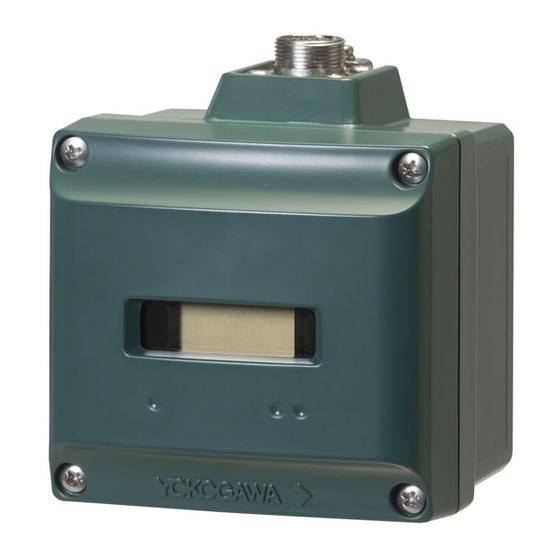
Page 22: Component Names
Signal Frame Ground * Signal Ground Power Supply Integral indicator Transmit/Receive Data positive Transmit/Receive Magnet switch 1 Data negative * W ired to the grounding terminal inside the FN510 housing. ** C onnector type of FN510: Magnet switch 2 JR13WRI-5S (connector mating with type of JR13WPI-5P) F0301.ai Battery terminal Grounding terminal Slide Switch Input terminal... -
Page 23: Installation
The FN110 terminal is covered with a cap during The installation procedure is as follows. shipping. Keep the cap attached until connecting 1. Check the direction of the pin, connect FN110 the FN110 or remote antenna cable to protect to FN510. the inside connection part. The unscrewed 2. Tighten the lock nut to torque of 1.2 N•m. cap should be stored in order to replace it Removal is the reverse procedure of the installation. immediately after the FN110 or remote antenna cable is removed. If there is a possibility that get wet with water, order FN510 with optional specification for a protection cap. Lock nut Installation Work • When performing on-site pipe fitting work that involves welding, use case to prevent the welding current to damage the FN510. • Do not use the FN510 as a foothold. NOTE • Before using FN510, install FN110. For detail on how to install FN110, refer to subsection 4.2.1 “Installation of FN110”. F0401.ai • To connect FN510 to the field wireless... -
Page 24: Mounting Of Fn510
“Installation and Connection of FN110”. • Remove the battery pack before installing FN110. Refer to subsection 8.3 “Replacing the Battery Pack” for the battery pack removing. • When installing FN110, fix the FN110 by tightening the lock nut. Screwing by holding the FN110 housing may cause failure such as cable disconnection. The same manner should be taken when removing the FN110. 4.2.2 Mounting of FN510 Bracket fastening bolt FN510 fastening bolt FN510 mounting bracket U-bolt nut Spring washer Bracket fastening nut 2-inch pipe U-bolt F0402.ai Figure 4.2 Vertical Pipe Mounting... - Page 25 Spring washer Bracket fastening nut 2-inch pipe U-bolt F0403.ai Figure 4.3 Horizontal Pipe Mounting To install FN510 on a 50A (2-inch) pipe, follow the procedure below. 1) Assemble the FN510 mounting bracket. 2) Install FN510 to the mounting bracket using provided bolt (4) with a torque 1.4 N•m. 3) Install FN510 mounting bracket to the 2-inch pipe by U-bolt. IM 01W03E03-01EN...
-
Page 26: Wiring
<5. Wiring> Wiring Notes on Wiring Cable Selection For wiring the sensor and the FN510, use a IMPORTANT shielded multi-core cable of AWG24 to 14. • Apply a waterproofing sealant to the threads Applicable Cables of the connection port. (It is recommended Cables for industrial equipment such as; that you use non-hardening sealant made of • Control cable silicon resin for waterproofing.) Use the following grounding cable. • Lay wiring as far away as possible from electrical noise sources such as large Applicable Cables transformers, motors and power supplies. Insulated cables for industrial equipment such as; • Remove the wiring connection dust-caps • 600 V polyvinyl chloride insulated wires (IV); JIS... -
Page 27: Installation And Connection Of Fn110
3) Protect the connection as necessary. For cable to protect the inside connection part. The details of the protection, refer to subsection unscrewed cap should be stored in order to 4.2.1 “Installation of FN110”. replace it immediately after the FN110 or remote 4) Fix the FN110 to the mounting bracket. antenna cable is removed. If there is a possibility that get wet with water, order FN510 with FN110 holder bolt optional specification for a protection cap. FN110 FN110 mounting bracket 5.3.1 Installation of FN110 FN110 holder Location of FN110 Mount the FN110 at the proper location according to the wireless environment described in subsection Remote 2.4 “Selecting the Installation Location”. The... -
Page 28: Installation Of Fn110
5.3.2 Connection of FN110 Accelerometer To install FN110 with remote antenna cable, follow the procedure below. Strip the insulated cover of the cable end. Remove the battery pack from FN510 before 5.4.1 Connecting Input Terminal and connecting the remote antenna cable. Grounding Terminal 1. Connect the FN110 and the FN510 with the dedicated remote antenna cable. Tighten the Vertical Connection connector of the remote antenna cable with a torque of 1 to 1.2 N•m. The minimum bending radius should be more than 100 mm. 2. Protect the connectors of the FN110 and remote antenna cable as necessary. For details of the protection, refer to subsection 4.2.1 Grounding “Installation of FN110”. - Page 29 <5. Wiring> Wiring external device IMPORTANT When wiring LN01, connect LN01 to FN510 shown as Figure 5.7. When using a cable gland, apply a water proofing sealant to the threads of the cable gland. (It is recommended that you use non- Red Black White Screen hardening sealant made of silicon resin for waterproofing.) Input Terminal LN01 Piezoelectric Accelerometer Input terminal is a spring terminal. When using a F0507.ai solid conductor cable or with sleeve, connect the cable to the input terminal. When using a standard Figure 5.7 External Device Connection Diagram conductor, push down the top of a cable inlet and insert the cable. To unplug the cable, push down the CAUTION top of a cable inlet and unplug the cable.
-
Page 30: Grounding
<5. Wiring> Grounding Class D grounding with the grounding resistance of 100Ω or less is necessary. To connect the grounding cable to FN510 directly, use the ground terminal on the top of the housing. Do not share the ground wiring with other devices. Ground Wiring Connect the grounding cable to ground terminal on the top of the housing. Grounding terminal F0508.ai Figure 5.8 Grounding Terminal CAUTION Grounding is required for safe operation. Input Cable Wiring The input cable shield should be connected to grounding terminal inside of the housing. Please refer to Figure 5.4 and Figure 5.7. -
Page 31: Operation
(2) Power On and Connecting to the Field display of the integral indicator or the device Wireless Network configuration tool, refer to subsection 8.10.3 “Errors and Countermeasures” for the corrective Insert batteries into the battery case, and install action. to the FN510. For details of installation of battery, refer to subsection 8.3 “Replacing the Battery Pack” and subsection 8.4 “Replacing the Batteries”. Verify and Change the FN510 Setting and Provisioning is to set the security and network Values information. For details of provisioning, refer to The followings are the required settings of the section 6.3 “Connecting to the Field Wireless... -
Page 32: Starting Operation
Preparation Work Prior to Connecting to a • Setting provisioning information Field Wireless Network • Creating a provisioning information file FN510 does not need to be connected with a (1) Setting provisioning information physical wire. Instead of physical wiring, to set Set the device tag and Network ID using a security and field network information is required. FieldMate provisioning function. The device tag, This procedure is called a provisioning. Network ID, and join key are set in the field wireless FN510 supports provisioning via infrared device. It is not necessary to input a join key communication using a provisioning device and because FieldMate automatically generates it. can be securely connected to a network. If the • Setting device tag provisioning information is not set, the FN510 The device tag is used for the user to recognize cannot be connected to the field wireless network. the field wireless device. NOTE • Setting Network ID This is the Network ID for the field wireless Before provisioning, connect the FN110. For... - Page 33 (Disconnect) (Connect) F0607.ai (Connect) Figure 6.7 Display showing Join State Confirm connecting status: Join (c) Operation (d) NOTE (Publish) F0603.ai If the FN510 searches the field wireless network * B y using a magnet switch or field device configuration tool, transitions to the Deep sleep state from any state. for long time low ambient temperature condition, Figure 6.3 Wireless Status Transition sometimes error “AL.20 LOWBAT” is displayed on the integral indicator. It occurs because of (a) Deep Sleep battery characteristics even when using new batteries. After joining to the field wireless network, this error will be cleared within one hour if battery has no failure.
-
Page 34: Display Contents Of The Integral Indicator
• Startup • Alert Shutting Down Process Value The process value obtained from the sensor is When shut down the FN510, remove the battery displayed. For detail information about the display pack or set the FN510 to deep sleep mode by the settings, refer to section 7 “Setting Parameters”. device configuration tool or magnet switch. When sensor data is more than five orders of NOTE magnitude, scroll automatically after 2 seconds. • Refer to subsection 8.3 “Replacing the Battery Pack” for the battery pack removing. • When storing the FN510 with a battery pack inserted, it is recommended to put the FN510 into deep sleep mode to conserve battery power. For details on how to switch to F0608.ai deep sleep mode, refer to subsection 7.3.14 Figure 6.8 Example of Data Scrolling “Switching to the Deep Sleep Mode”. When publish is not configured, following is displayed. F0609.ai Figure 6.9 Display when Publish is not Configured IM 01W03E03-01EN... -
Page 35: Setting Parameters
<7. Setting Parameters> Setting Parameters Preparing Software FN510 can remotely handle sensor type changes, Tag No. setup, monitoring of self-diagnostic results, according to communication with the fi eld wireless 7.2.1 Softwares for the Field Wireless confi guration tool or the device confi guration tool. Confi guration Tool and the Device Confi guration Tool Preparation for Parameter Before using the device confi guration tool, confi rm Setting that CF/DD and DeviceDTM for this product are installed in the device confi guration tool. -
Page 36: Parameter Usage And Selection
7.3.1 Parameter Usage and Selection Before setting a parameter, please see the following table for a summary of how and when each parameter is used. IMPORTANT After setting and sending data with the field wireless configuration tool or the device configuration tool, wait 30 seconds before turning off the FN510. If it is turned off too soon, the setting will not be stored in the FN510. Table 7.1 Parameter Usage and Selection Item Description Tag No. Sets the Tag No. for Device Tag (software tag). The Tag No. can be set sixteen characters (alphanumeric characters, including – ). -
Page 37: Parameter Setting Flow
<7. Setting Parameters> 7.3.2 Parameter Setting Flow Figure 7.2 shows the fl ow of setting parameter. Please set these parameter according to the function to use. Start TRANSDUCER block: Sensing mode, Sensing Function Sampling Frequency, Sampling Points AI block: Process Value Type AI block: PV range Scaling Funtion Direct Process Value Type ? Indirect AI block: Scale TRANSDUCER block: HILO Limit Alarm Enable Disable... -
Page 38: Function Block And Menu Tree
<7. Setting Parameters> (3) Analog Alarm Function This function is used to inform that the process value has exceeded the threshold. Use in such cases to ensure the detection of the abnormal vibration in device patrol function of “PRM”. For more information please refer 7.3.10 “Analog Alarm Function”. 7.3.3 Function Block and Menu Tree (1) Function Block The function of FN510 is shown below. Some functions may not be available depending on the device configuration tool used. When the device configuration tool of our recommendation is used, the software attached to the Field Wireless Integrated Gateway or Field Wireless Management Station is necessary for setting the dotted line part. Refer to subsection 8.2 “Recommended Products List” for the field wireless configuration tool of our recommendation. IM 01W03E03-01EN... - Page 39 <7. Setting Parameters> (UAPMO) (Configuration) Menu (Online) ・ UAPMO ・ Configuration ・ UAP Option ・ UDO ・ Diagnostics ・ Hardware Write Protect ・ CO ・ Alerts ・ Static Revision ・ TRANSDUCER ・ Power Status ・ Reset Energy Left ・ AI1 ・...
- Page 40 <7. Setting Parameters> Menu (Online) (Continued) (TRANSDUCER) (Block Info) ・Tag Description ・Block Info ・Block Mode (Block Mode) ・Configuration/Calibration ・Others ・Mode.Target ・Mode.Actual ・Mode.Permitted ・Mode.Normal (Configuration/Calibration) ・Model ・Serial Number ・Wireless Status ・Display Selection ・LCD Intermittent Time ・LCD Exp Mode ・Measurement Rate ・Sensing Mode * ・Sampling Frequency * ・Sampling Points * ・HILO Alarm Limit Enable...
- Page 41 <7. Setting Parameters> (2) Menu Tree The menu tree of our recommended device configuration tool is shown below. Refer to subsection 8.2 “Recommended products list” for the device configuration tool of our recommendation. (Device Configuration) (UAPMO) (Configuration/Setup) Online Menu ・UAP Option ・Device Configuration ・UAPMO ・Configuration/Setup ・Hardware Write Protect ・Diagnostics ・TRANSDUCER ・Static Revision ・Process Variable ・AI1 ・Reset Energy Left ・AI2 ・Energy Harvest Type ・AI3 (Identification) ・Version Revision ・CTS Version ・ITS Version ・Identification Number...
- Page 42 <7. Setting Parameters> (AI1/AI2/AI3) (Block Info) Online Menu Device Configuration (Continued) (Continued) ・Tag Description ・Configuration/Setup (Block Mode) ・Mode.Target ・Mode.Actual ・Mode.Permitted ・Mode.Normal (Configuration) (Block Mode) ・Mode.Target ・Block Mode ・Mode.Actual ・Concentrator OID ・Mode.Permitted ・Scale * ・Mode.Normal ・PV Range * ・Sensor Serial ・Process Value Type * (Scale) ・PV Energy Left Enable ・Scale.EU at 100% *...
-
Page 43: Parameters For Wireless Communication
<7. Setting Parameters> 7.3.4 Parameters for Wireless NOTE Communication When the FN510 detects AL.01, AL.02 and (1) Network Information AL.03 error, the LCD display does not dim CO block: Configuration regardless of the status in LCD mode. See Table The network-related information can be checked. 8.4 for details. (2) Update Time 7.3.5 Tag and Device Information CO block: Data publication period Set the update time value to the data publication You can specify the Device Tag when ordering period in the CO block within the range of 10 to the corresponding FN110 Field Wireless 3600 seconds. Communication Module. Device Tag and device information can be checked NOTE as follows. If you set the update time less than 10 sec, ... -
Page 44: Sensor Input
Output range parameter. measure velocity around 160 Hz. NOTE NOTE The scaling function effects to each Transducer The appropriate mode should be selected to Value individually. For example, if the scaling accurately measure. function is enabled on AI1 and AI2, there is no Measureable frequency and measureable effect on PV of AI3. frequency in each mode are described in subsection 7.3.11 and subsection 7.3.12. ■Setting example Temperature characteristic with combination of Figure 7.3 shows a diagram of the case that is set FN510 and LN01 is described in Section 10.1. up as follows: Process Value Type = Indirect Transducer block: Sampling Frequency PV Range.EU at 0% = 0 Sampling frequency should be more than twice PV Range.EU at 100% = 100 the upper frequency limit of the vibration to be Scale.EU at 0% = 30 measured,. and is recommended to be more than Scale.EU at 100% = 180 two and a half times. PV Range. PV Range. EU at 100% EU at 0%... -
Page 45: Analog Alarm Function
7-11 <7. Setting Parameters> 7.3.10 Analog Alarm Function 7.3.11 Frequency Characteristics Self-diagnostics function is used to inform that the FN510 have frequency filters in accordance with process value has exceeded the threshold. For the Sensing Mode and Sampling Frequency. more information about self-diagnostics function, By switching the Sensing Mode, you can switch the refer to 7.4”Self-Diagnostics” frequency characteristic shown by the solid line in Figure 7.5 - 7.7. Transducer block: HILO Alarm Limit Enable In addition, in accordance with the Sampling To disable analog alarm function of each AI block, Frequency, you can further select the frequency set “Disable” to “HILO Alarm Limit Enable”. characteristics shown in dotted line. AI block: High High Alarm, High Alarm, Low Alarm, Low Low Alarm. Each AI reports Analog Alarm when PV exceeds Alarm Limit value. AI block: Alarm Hysteresis. The value of hysteresis of analog alarm. When “Process Value Type” is set to “Direct”, hysteresis should be specified by the ratio [%] to the 1000 10000 Frequency [Hz] PV_Range. When “Process Value Type” is set to... -
Page 46: Measurement Range
7-12 <7. Setting Parameters> 7.3.13 Write Protect NOTE Hardware write protection and software write protection functions are available for FN510. If Velocity LPF 160 Hz mode is selected, frequency only around 160 Hz is extracted. Hardware Write Protection Therefore, this mode should be used only when Hardware Write Protection is set by slide switch on the vibration to be measured is around 160 Hz the front panel back. such as an electric motor. Software Write Protection 7.3.12 Measurement Range Software Write Protection is set by the parameter of software write protect of UAP Option in UAPMO The measurement range depending on the Sensing block. Mode. For the relationship between hardware write Measurement range in accordance with the protection and software write protection, refer to Sensing Mode, is shown in Figure 7.8 and Figure... -
Page 47: Switching To The Silence Mode
<7. Setting Parameters> Self-Diagnostics Restart Restart by re-connection of the battery pack. 7.4.1 Identify Problems by Using the Infrared Communication Device Configuration Tool Start by receiving infrared communication. Use the The device configuration tool allows checking the wireless field device configuration tool (for infrared) self-diagnostic results and settings of the FN510. or device provisioning tool. First, check Diagnostic Status of the self-diagnostic results. Magnet Switch Operation Procedure to Call Up the Self-Diagnostic Start by touching a magnet to magnet switch 1 for Parameter 10 seconds. UAPMO block: Diagnostic Status CAUTION... -
Page 48: Alert Report
7-14 <7. Setting Parameters> NOTE Be careful when changing the alert category and turning detection on and off as described above. Be sure to set UAP Option Enable diagnostic status configuration to disable again to prevent setting errors. 7.4.2 Alert Report FN510 generates and alert information related to Diagnostic Status and Analog Alarm, automatically sends to a field wireless gateway. To use this function, the following alert setting is necessary. When “Out of Service” for Diagnostic Status alert is required, choose “FALSE” for [Out of Service. Alert Disable] in the UAPMO block. Refer to the field wireless gateway User’s Manual for the setting procedure to obtain the alert information from the gateway. The alert report consists of the list of parameter name as shown Table 7.3. Table 7.3 Contents of Alert Report Parameter name Description DetectObjectTLPort Alert detection port UAP (0xF0B2) fixed DetectObject Alert detection block... -
Page 49: Checking With Integral Indicator
7-15 <7. Setting Parameters> 7.4.3 Checking with Integral Indicator NOTE If an error is detected by running self-diagnostics, an error number is displayed on the integral indicator. If there is more than one error, the error number changes at 2 seconds interval. See Table 8.4 regarding the alarm codes. F0714.ai Figure 7.10 Error Check with Integral Indicator Table 7.4 Diagnostic Status NAMUR NE107 Bits Contents Categorization* Bit31(MSB) F:Failure status Bit30 C:Function check status Bit29 O:Out of specification status Bit28 M:Maintenance required status Bit27 Faults in electronics... - Page 50 Description Contents Object Type Category* Faults in UAPM ADAPTER FAIL FN510 failure electronics O (1) ANTENNA FAIL FN110 failure RS485 FAIL Communication failure between FN110 and FN510 Faults in sensor or SENSOR FAIL Communication failure between actuator element FN510 and connected devices Installation, DEVICE_CONNECTION_ Connection error between FN510 and calibration problem connected devices DEVICE_PUBLISH_ Publication interval is out of INTERVAL_E Out of service...
-
Page 51: Maintenance
Recommended Products List dry cloth. If static electricity cannot be suppressed, Yokogawa-recommended Instrument check that the surrounding atmosphere does Provisioning Device Tool • F ieldMate (R2.03 or later) not contain explosive gas or steam before • P rovisioning Device Tool replacing the Battery Pack. • I nfrared Adapter certified by Yokogawa • Be sure to use a battery pack that is Supplier: ACTiSYS Product name: IrDA InfraRed USB Adaptor indicated as “Rev.1” for explosion protected Product number: IR224UN-LN96 (9600bps) instruments. Field Wireless Configuration Tool • F ield Wireless Integrated Gateway attached Software Field Wireless Configurator Field Wireless Management Tool • F ield Wireless Management Station attached Software... - Page 52 <8. Maintenance> Removing Remounting 1. Loosen the four screws on the front panel. 1. Insert the new battery pack. The orientation of 2. Pull the lever in the direction of the arrow in the battery pack, “PART NO.” display is the front Figure 8.1. and connector cable is left side. 3. Pull out the battery connector from the front 2. Plug the battery connector into the terminal panel back. on the front panel back. Connect facing down 4. Pull the battery pack. the white surface of the connector. Push the connector until it touches the back of the front panel then slide it to the left. 3. Push the lever in the direction of the arrow in Figure 8.2. 4. Close the front panel and tighten the four screws to a torque of 0.7 N • m.
-
Page 53: Replacing The Batteries
<8. Maintenance> Replacing the Batteries The batteries in the battery pack can be replaced. Batteries are not installed when shipped from the factory. Assemble the battery pack as follows. WARNING Be sure to replace the batteries or open and close F0805.ai the battery pack in a non-hazardous area. Doing Figure 8.4 Assembling the Battery Pack so in a hazardous area could cause an explosion. Handling Batteries CAUTION This battery pack uses two primary lithium- thionyl chloride batteries. Each battery contains When replacing the batteries, be sure to replace approximately 5 grams of lithium, for a total of 10 the two batteries at the same time and do not grams in each pack. Under normal conditions, use an old and a new battery together. the battery materials are self-contained and are not reactive as long as the batteries and the pack Disassembling integrity are maintained. Care should be taken to 1. Loosen a battery case fixing screw. -
Page 54: Switching Lcd Display
<8. Maintenance> Use the following dedicated parts for the battery Procedure to replace and dispose of the batteries of the product pack and batteries. Battery Pack Below an explanation about the new EU Battery Directive (DIRECTIVE 2006/66/EC). This directive Part number: F9090FD (with batteries) is only valid in the EU. Part number: F9090GD (without batteries) Batteries are used for this product. When you *1: I f you need F9090FC, please purchase F9090FD. F9090FD is a set of F9090FC and instruction manual. remove batteries from this product and dispose *2: I f you need F9090GC, please purchase F9090GD. F9090GD them, discard them in accordance with domestic is a set of F9090GC and instruction manual. -
Page 55: Replacing The Fn110
<8. Maintenance> Replacing the FN510 Table 8.2 Wireless Status Integral Indicator Description This subsection describes the procedure for Searching for Backbone replacing the FN510. Replace the FN510 as Router or Router to follows. connect. It is not connected to the 1. Back up the configuration of the FN510. field wireless network. 2. Remove the battery pack. F0806.ai 3. Remove the FN110 and the accelerometer, and Discovering the connection install them to the new FN510. destination, and is doing the Join process. 4. Remounting the battery pack. It is not connected to the 5. Restore the backed up configuration of the... -
Page 56: Basic Troubleshooting Flow
The following shows an example of the flow for is actually abnormal or a problem exists in the troubleshooting. measurement system. If the problem is in the Refer to this example and Table 8.3. Locate measurement system, isolate the problem and the problem and take the corresponding decide what corrective action to take. countermeasure. FN510 is equipped with a self-diagnostic function which will be useful in troubleshooting, and this The following phenomena indicate that this instrument may be out of operation. product is equipped with an integral indicator [Example] and it will show an alarm code as a result of self- • No output signal is delivered. • Process variable changes but the output diagnosis. -
Page 57: Errors And Countermeasures
FN510 Recovers Normal action Check the conditions TEMP HI temperature when the ambient out of device is above temperature temperature specification +85°C returns to of the FN510 +85°C below ADAPTER FN510 Recovers TEMP LO temperature when the is below temperature -40°C returns to -40°C or more ANTENNA... - Page 58 * AL.50 25 Installation, DEVICE_CONN Connection None Output value: Check if the calibration ECTION_ERR error Hold previous connected problem between value device is FN510 Output properly and the status: BAD connected to connected Configuration FN510. device Replace the device if it is properly connected. AL.52 25 Installation, DEVICE_PUBLI...
- Page 59 <8. Maintenance> Release/ NAMUR recovery Integral Diagnostic Diagnostic Output NE107 Cause conditions Action indicator Status Status Detail Operation category * (except restart) * AL.90 21 Fault AI1_HI_HI_ AI1 High High None Normal Action Check AI1 prediction: ALARM Alarm block output Maintenance value required AI2_HI_HI_ AI2 High High Check AI2...
-
Page 60: Parameter Summary
Refer to Table W(P) Configuration Status when Enable diagnostic status configuration 9.2. in UAP Option is set to Enable. 0x08: F:Failure status 0x04: C:Function check status 0x02: O:Out of specification status 0x01: M:Maintenance required status Find Device When set a value other than 0, FN510 displays “Squ.” on the LCD. The value means the display duration. After displaying, this value returns to 0. Unit: second Range: 0 to 60 IM 01W03E03-01EN... - Page 61 Energy Harvest Available to write note into this parameter. W(P) Type Power Supply Indicates the measured power supply voltage (V). Voltage Hardware Write Indicates the status of the hardware write protection Protect switch. 0: Off 1: On Antenna Indicates the temperature of the FN110. Temperature Adapter Indicates the temperature of the FN510. Temperature Temperature Selects the temperature unit to be indicated on °C W(P) Unit Antenna Temperature and Adapter Temperature. 1000: K 1001: °C (default) 1002: °F 1003: °R Other Faults The On/Off or priority for Other Faults Alert can be 1. Off W(P) Alert set.
- Page 62 <9. Parameter Summary> Object Attribute Handling Label Description Default value Power Low Alert The On/Off or priority for Power Low Alert can be 1. Off W(P) UAPMO set. 2. 15 block 1. On/Off setting (continued) 0: On, 255: Off (default) 2. Alert report priority: 0 to 15 (default: 15) Power Critical The On/Off or priority for Power Critical Low Alert 1. Off W(P) Low Alert can be set. 2.
- Page 63 3. Actual_Phase PUB_ITEM_ Maximum PUB_ITEM value. PUB_ITEM_ PUB_ITEM number. PUB_ITEM Indicates the PUB_ITEM information. The following shows the components. 1. ObjectID 2. AttributeID 3. AttributeIndex 4. Size Tag Description Memo field available to write anything. Transducer W(P) TRANSDUCER Model Indicates the model name of the FN510. block Serial Number Indicates the serial number of the FN510. Display Select PV Value displaying on the integral indicator. W(P) Selection Following value can be selected depending on the Sensor Type. SensorType Value DIDO 32:BI1(Default) 33:BI2 64:BO1 DI Pulse Count 0:AI1(Default) 4-20 mA...
- Page 64 0: Idle 1: Joined Measurement Indicates the publish period. Rate Unit: second Special Cmd Special function parameter. Normal mode 0: Normal mode (default) 1: Deep-sleep mode Sensor Type Select the type of sensor to be connected to the Vibration W(P) FN510. Sensor 120: Vibration sensor (default) 139: Not Used HILO Alarm Limit The Enable/Disable for Analog limits of AI blocks Disable W(P) Enable 0:Disable (Default) 1: Enable Sensing Mode Select the sensing mode. When the data of these Velocity W(P) parameters is rewritten, it is necessary to set the operational mode of the block to O/S (Out of Service).
- Page 65 <9. Parameter Summary> Object Attribute Handling Label Description Default value Process Value Output object of AI1(DI Pulse Count or 4-20 mA). 1. --- 1. Value: output value of the object. 2. --- block 2. S tatus: indicates the status of the object’s output value. Block Mode Select the block’s operation status. O/S and Auto 1. Auto W(P) block can be selected. 2. Auto 1. Target: Specify object mode of the object. 3. O/S|Auto 2. Actual: Indicates current mode of the object. 4. Auto block 3. P ermitted: Indicates the mode selected by Target of the object.
- Page 66 <9. Parameter Summary> Object Attribute Handling Label Description Default value Tag Description A universal parameter to store the comment that W(P) describes the tag. Up to 32 characters can be used. block Simulate Switch A simulation function switch for the object. Disable W(P) 1: Disable (default) 2: Enable block Simulate Value When Simulate Switch is set to Enable, this value W(P) is used as the input value for the object. The input value can be changed. block PV Energy Left Allows assign the Energy Left to AI1.PV.Value when W(P) (continued) Enable...
- Page 67 <9. Parameter Summary> TRANSDUCER Object (TRANSDUCER block) TRANSDUCER algorithm Mode and Mode.Target Status handling from Operator to AI1 Peak & RMS to AI2 Analog from Sensor Integration Down Calculate Filter Sample to AI3 Filter Sample Value (fc=10kHz) (20kHz) Sensing Sampling Sampling Mode...
- Page 68 <9. Parameter Summary> Table 9.2 Diagnostic Status Detail Diagnostic NAMUR Diagnostic Status Detail Description status NE107 assignment bit Category Diagnostic Status Detail.1 ADAPTER FAIL FN510 failure Bit27 ANTENNA FAIL FN110 failure Bit27 RS485 FAIL Communication failure between FN110 and Bit27 FN510 SENSOR FAIL Disconnection or communication error, Bit26 between the connected device and FN510 DEVICE_PUBLISH_INTERNAL_ Update time is out of specification...
-
Page 69: Connecting Sensor
Measurement accuracy with combination of LN01 Piezoelectric Accelerometer (reference value) Conditions Accuracy(100 Hz) Ambient temperature -40 to 85ºC, the entire measurement Acceleration: -27 to 17% of reading ± 2 m/s rms range Velocity: -35% to 25% of reading ± 1 mm/s rms Ambient temperature 25 ± 10ºC, the entire measurement Acceleration: ± (15% of reading + 0.8 m/s rms) range Velocity: ± (23% of reading + 0.2 mm/s rms) For more information about the accuracy and temperature characteristics of LN01, refer to LN01 Piezoelectric Accelerometer (for FN series) (GS 01W03H01-01EN). NOTE An ambient temperature affects a sensitivity of accelerometer. If a high accuracy measurement is required, please install FN510 and LN01 to a location where a temperature change is small. IM 01W03E03-01EN... -
Page 70: General Specifications
11-1 <11. General Specifications> 11. General Specifications Please refer to GS 01W03E01-01EN for the latest Power Supply: information. Power supply to the FN110 Supply voltage: 3.5 V 11.1 Standard Specifications Supply current: 50 mA Power supply to sensors See Table 11.1 POWER SUPPLY SPECIFICATIONS Integral Indicator (LCD display): 5-digit numerical and status display. Display Battery: contents and display on/off can be controlled Dedicated battery pack. with a magnet (not included). Rated voltage: 7.2 V The indicator displays the following information: Rated capacity: 19 Ah... - Page 71 <11. General Specifications> REGULATORY COMPLIANCE PHYSICAL SPECIFICATIONS STATEMENTS Connections: This product satisfies the following standards. Refer to “MODEL AND SUFFIX CODES” * Please confirm that an installation region fulfills Housing Material: an applicable standard. If additional regulatory Plastic (Polycarbonate) information and approvals are required, contact a Yokogawa representative. Weight: CE Conformity: 500 g (without mounting bracket and battery) EMC Directive: Mounting: EN61326-1 Class A Table 2, EN55011 Class A 2-inch pipe mounting RoHS Directive: EN50581 ATEX Directive: See “OPTIONAL SPECIFICATIONS (For Explosion Protected Types)”...
-
Page 72: Model And Suffix Codes
11-3 <11. General Specifications> 11.2 Model and Suffix Codes Model Suffix Code Descriptions FN510 ..................Field Wireless Multi-Function Module General Inter module -A1 ..........Digital communication for FN series Specifica- communication tion -A ..........Always A Housing material 0 .......... Plastic (Polycarbonate) 0 ........Horizontal connection: blind plug, Electrical connection Vertical connection: G 1/2 female * 1 ........Horizontal connection: blind plug, Vertical connection: 1/2 NPT female * 2 ........Horizontal connection: blind plug, Vertical connection: M20 female * 6 ........Horizontal connection: blind plug,... -
Page 73: Optional Specification (For Explosion Protected Type)
11-4 <11. General Specifications> 11.3 Optional Specification (For Explosion Protected Type) Item Description Code Factory United States FM Intrinsically safe Approval (United States) Applicable Standards: C lass 3600:2011, Class 3610:2010, Class 3810:2005, Mutual ANSI/ISA-60079-0-2013, ANSI/ISA-60079-11-2014, (FM) NEMA 250-2003, ANSI/IEC-60529-2004 (R2011) Intrinsically safe for Class I, II, III, Division 1, Groups C, D, E, F & G, Class I, Zone 0, in Hazardous Locations, AEx ia IIB Enclosure: IP66 and Type 4X, Temperature Class: T4, Amb. Temp. : –40 to 70°C (–40 to 158°F) For connection to Class I, II, III, Division 1, Groups A, B, C, D, E, F & G, FS17 Class I, Zone 0, in Hazardous Locations, AEx ia IIC Electrical Parameters: Wireless Communication (Connector) Uo = 5.88 V, Io = 483 mA, Po = 779 mW, Co = 5.82 μF, Lo = 25 μH Sensor Input (Terminal 1 to 4) Uo = 5.88 V, Io = 145 mA, Po = 213 mW, Co = 43 µF, Lo = 1.6 mH Sensor Output (Terminal 5, 6)* Ui = 30 V, Ii = 200 mA, Pi = 1 W (linear source), Ci = 10 nF, Li = 0 μH Dielectric Strength: 500 V a.c. r.m.s., 1 minute Canada FM Intrinsically safe Approval (Canada) Applicable Standards: C AN/CSA-C22.2 No. 0-10 (R2015), CAN/CSA-C22.2 No. 94.1-07 (R2012), CAN/CSA-C22.2 No. 94.2-07 (R2012), CAN/CSA-C22.2 No. 60079-0:11, CAN/CSA-C22.2 No. 60079-11:14, CAN/CSA-C22.2 No. 60529-05 (R2015),... -
Page 74: Optional Specifications
11-5 <11. General Specifications> 11.4 Optional Specifications Item Description Code Protection cap * Metal waterproof cap Wired tag plate 316 SST tag plate wired onto module *: When protection cap is not specified, dust-cap is attached. 11.5 Optional Accessories Item Parts Number Description Battery pack assembly F9090FD * Battery case, Lithium-thionyl chloride batteries * 2 pieces Batteries * F9915NR Lithium-thionyl chloride batteries * , 2pieces Battery case * F9090GD * Battery case only Magnet F9840PA For magnet switch operation *1: If you need F9090FC, please purchase F9090FD. F9090FD is a set of F9090FC and instruction manual. *2: Tadiran TL-5930/S *3: Alternatively, Tadiran SL-2780/S, TL-5930/S or VITZROCELL SB-D02 batteries can be purchased from your local distributor. *4: If you need F9090GC, please purchase F9090GD. F9090GD is a set of F9090GC and instruction manual. IM 01W03E03-01EN... -
Page 75: Dimensions
11-6 <11. General Specifications> 11.6 Dimensions 2-inch pipe mounting (for horizontal piping) 112 (4.41) Unit: mm (approx. inch) 48 (1.89) 100 (3.94) (1.14) FN110 Grounding terminal Blind plug Integral indicator Electrical connection Magnet switch 2 Magnet switch 1 Mounting bracket 40 (1.57) 93 (3.66) 2-inch pipe 80 (3.15) -
Page 76: Lcd Display Character List
11-7 <11. General Specifications> 11.7 LCD Display Character List . (Period) - (Minus) F1103.ai IM 01W03E03-01EN... -
Page 77: Revision Information
Revision Information Title : FN510 Field Wireless Multi-Function Module (Accelerometer input) Manual No. : IM 01W03E03-01EN Edition Date Page Revised item Feb. 2017 ― New Publication Add section 1.5 Apr. 2017 ― Update CE Conformity (RoHS) IM 01W03E03-01EN...
Need help?
Do you have a question about the FN510 and is the answer not in the manual?
Questions and answers