Table of Contents
Advertisement
Quick Links
Advertisement
Table of Contents

Subscribe to Our Youtube Channel
Related Manuals for YOKOGAWA FA-M3 FA Link H Module


Summary of Contents for YOKOGAWA FA-M3 FA Link H Module
- Page 1 FA Link H Module Fiber-optic FA Link H Module Model: F3LP02-0N, F3LP12-0N IM 34M06 H43-01E Applicable Modules: Model Code Model Name F3LP02-0N FA Link H Module F3LP12-0N Fiber-optic FA Link H Module IM 34M06 H43-01E 6th Edition Yokogawa Electric Corporation...
- Page 2 Blank Page...
-
Page 3: Applicable Product
The document number for this manual is given below. Refer to the document number in all communications, including when purchasing additional copies of this manual. Document No.: IM 34M06H43-01E IM 34M06H43-01E 6th Edition : Aug.30, 2019-00 All Rights Reserved Copyright © 1999, Yokogawa Electric Corporation... -
Page 4: Precautions
- Every effort has been made to ensure accuracy in the preparation of this manual. However, should any errors or omissions come to the attention of the user, please contact the nearest Yokogawa Electric representative or sales office. Safety Symbols - ”Handle with care.”... - Page 5 WARRANTY that is provided separately. - Yokogawa Electric assumes no liability to any party for any loss or damage, direct or indirect, caused by the use or any unpredictable defect of the product.
- Page 6 Software Supplied by the Company - Yokogawa Electric makes no other warranties expressed or implied except as provided in its warranty clause for software supplied by the company. - Use the software with one computer only. You must purchase another copy of the software for use with each additional computer.
- Page 7 General Requirements for Using the FA-M3 / e-RT3 Controller Set the product in a location that fulfills the following requirements: - INDOOR USE ONLY - This product is an open equipment. The product must be installed in a metallic panel enclosure with an impact rating IK08 or more.
- Page 8 Configure and route cables with noise control considerations: - Perform installation and wiring that segregates system parts that may likely become noise sources and system parts that are susceptible to noise. Segregation can be achieved by measures such as segregating by distance, installing a filter or segregating the grounding system.
- Page 9 - Refer to “A3.5.4 Grounding Procedure” in the “Hardware Manual” for attaching the grounding wiring. Authorized Representative: - The Authorized Representative for this product in the EEA is: Yokogawa Europe B. V. Euroweg 2, 3825 HD Amersfoort, The Netherlands IM 34M06H43-01E...
- Page 10 viii General Requirements for Using the FA-M3 Slave Units (TAH Series) C onnect YHLS cable to SHIELD terminal: - Connect the DRAIN line of the YHLS cable to the SHIELD terminal of the YHLS master module securely. Failing to do so may affect the performance of the YHLS system.
- Page 11 With reference to the equipment types in the WEEE directive, this product is classified as a “Monitoring and Control instruments”. When disposing of products in the EU, contact your local Yokogawa Europe B. V. office. Do not dispose of this product in domestic household waste.
-
Page 12: Introduction
Introduction Overview of the Manual FA Links are networks through which data are exchanged between FA-M3 systems. Data link is achieved through link relays and link registers on these FA links. Other User’s Manuals manual(s) read depends module used. - Page 13 F3BP20 F3BP30 For Functions: BASIC CPU Modules and YM-BASIC/FA Programming Language (IM34M06Q22-01E) For BASIC programming: BASIC Programming Tool M3 for Windows (IM 34M06Q22-02E) Common for all sequence CPU modules For the FA-M3 specifications and configurations* , installation and wiring, test run, maintenance, and module installation limits for the whole system: Refer to the relevant product manuals for specifications except for power supply modules, base modules, input/output modules, cables and terminal units.
-
Page 14: Copyrights And Trademarks
Copyrights The copyright of the programs and online manuals contained in the software medium of the Software Product shall remain in YOKOGAWA. You are allowed to print the required pages of the online manuals for the purposes of using or operating the Product; however, reprinting or reproducing the entire document is strictly prohibited by the Copyright Law. -
Page 15: Table Of Contents
TOC-1 FA Link H Module Fiber-optic FA Link H Module IM 34M06H43-01E 6th Edition CONTENTS Applicable Product ....................i Precautions ......................ii Introduction ......................x Copyrights and Trademarks ................xi Overview ..................1-1 F3LP02-0N and F3LP12-0N Modules ............. 1-1 Operation Mode ..................1-1 Link Device .................... - Page 16 TOC-1 Attaching and Detaching Modules ............3-6 Wiring......................3-8 F3LP02-0N ................... 3-8 F3LP12-0N ................... 3-9 Applying the Power ................3-12 F3LP02-0N ..................3-12 F3LP12-0N ..................3-12 Checking Communication Status ............3-13 3.8.1 FA Link Module Status ............... 3-14 3.8.2 Displaying Status of Local Station ..........
- Page 17 TOC-1 High-speed Mode ................. 7-1 CPU Module Configuration ..............7-1 7.1.1 Setting Device Capacity ............... 7-1 FA Link H Configuration ................. 7-3 Link Data Configuration ................7-4 7.3.1 Link Relays ................... 7-4 7.3.2 Link Registers ................7-5 Response Time ..................7-6 7.4.1 Response Time of Layered System ..........
- Page 18 Blank Page...
-
Page 19: Overview
Overview The FA Link H modules for interchanging data between FA-M3 CPUs allow the configuration of a high-speed data link over a long distance. F3LP02-0N and F3LP12-0N Modules - The F3LP02-0N FA Link H Modules use twisted-pair cables which allow easy installation and selection of four speeds -- 125 k, 250 k, 625 k and 1.25 Mbps. -
Page 20: System Configuration
System Configuration This section shows the system configurations that can be constructed using the FA-Link H Modules. 1.4.1 Single-layer System A single-layer system is a system with up to 32 modules connected through optical fiber cables or twisted-pair cables. Be sure to install the FA Link H module in a main unit. There is no restriction on the installed position in the main unit. -
Page 21: Multi-Layer System
1.4.2 Multi-layer System A multi-layer system refers to a system with multiple networks connected together. To interconnect multiple networks, attach 2 FA Link H modules to one CPU module to configure a multi-layer system. A unit to which two FA Link H modules are attached is called a relay station. -
Page 22: Ras Function
RAS Function - The link status can be checked using special relays or registers. - The F3LP02-0N module uses a bus-type communication configuration which allows all operating stations in a network to continue linking even in the event that a link module in the network, other than the master station, is down due to power failure or other reasons. -
Page 23: Specifications
Specifications Model Names and Specification Codes Basic Model Specification Code Specification Style Code Remarks Name Suffix Code Up to 32 stations …………… …………… F3LP02 125k/250k/625k/1.25Mbps 1km/500m/250m/100m Up to 32 stations Maximum total length of 10km …………… …………… F3LP12 Maximum distance between stations of 1km 1.25Mbps Operating Environment... -
Page 24: Cable Specifications
2.4.2 Specifications for Fiber Optic Cables To connect the F3LP12-0N module, use fiber optic cables supplied by Yokogawa Electric Corporation or the fiber optic cables listed in table 2.3 which have been tested for operation. Select cables according to the distance between the stations. For more details, contact the respective manufacturer. - Page 25 Note: For information on pulling eyes, see the fiber-optic lead-in cable laying pulling-eye assembly diagram in this manual. Note - Use the specified fiber-optic cables to avoid problems, malfunctions or under- performance. - KM6 cables cannot be used in submerged environments. Contact Yokogawa’s sales office for alternative solutions. IM 34M06H43-01E 6th Edition : Aug.30, 2019-00...
- Page 26 External Diagram of KM60 Optical connector Optical connector Serial No. Fiber-optic cord L + tolerance Optical connector Optical connector Identification marking Indentification marking Fiber-optic cord L + tolerance Tolerance +e (m) Length L (mm) L≦3 0.20 FB0242.VSD Note: There are 2 types of fiber-optic cords (KM60) with optical connectors of different shapes but the cable type cannot be specified by the customer.
- Page 27 External Diagram of KM61, KM62 Optical connector Indentification marking Identification marking Optical connector Protective tape winding or protective coating (End with sheath removed) (End with sheath removed) Fiber-optic cable Tension member Tension member 200±50mm 200±50mm L + tolerance Indentification marking Identification marking Optical connector Optical connector...
- Page 28 Cross-sectional View KM61, KM62, KM65 Fiber-optic single-core cord Tension member (plastic-covered steel wire) Lacing (plastic lacing) Inclusion (plastic yarn or fiber) Holding tape (plastic fiber) Heat-resistant PVC sheath (KM61, 65), LAP sheath (KM62) Model Manufacturer Item code External Dimensions() KM61 8.4mm ±1.0 2-C-V...
- Page 29 Fiber-optic Lead-in Cable Laying Pulling-Eye Assembly Diagram Unit: mm ① ② ③ ④ ⑤ 30 15 Rigid section ⑦ Approx. 50 Rigid section ⑥ ⑧ Approx. 500 Components Qty. ① Pulling eye ② Stopper screw (M6) ③ Flexible pipe When performing lead-in work, connect the pulling eye to the tow ④...
-
Page 30: External Dimensions
External Dimensions F3LP02-0N Unit: mm 12.1 83.2 28.9 F0251.VSD Figure 2.1 External Dimensions of the F3LP02-0N module F3LP12-0N Unit: mm 83.2 28.9 F0252.VSD Figure 2.2 External Dimensions of the F3LP12-0N module IM 34M06H43-01E 6th Edition : Aug.30, 2019-00... -
Page 31: Setup And Connection Of Modules
Setup and Connection of Modules Startup Procedures Set station numbers (See Section 3.3) Set parameters (See Section 3.4) Attach modules (See Section 3.5) You should refer to wiring precautions. Wiring (See Section 3.6) Switch on the power supply of all the stations connected. Apply power (See Section 3.7) Checking can be done using the WideField3 software. -
Page 32: Components And Their Functions
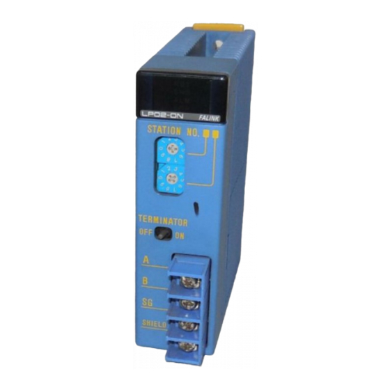
Components and their Functions F3LP02-0N Front view Indicators RDY: Lit when the internal circuit is functioning mormally SND: Lit when the transmission is functioning normally LP02-0N FA LINK ERR: Lit when errors occur. STATION NO. Station number setting switch: Set station numbers from 1 to 32. -
Page 33: F3Lp12-0N
F3LP12-0N Front view Indicators RDY: Lit when the internal circuit is functioning mormally LP12-0N FALINK SND: Lit when the transmission is functioning normally ERR: Lit when errors occur. STATION NO. Station number setting switch: Set station numbers from 1 to 32. Value at shipment is 01 Optical fiber connecting port. -
Page 34: Setting Station Numbers
Setting Station Numbers This sets the station number, which identifies a FA Link Module. Set the station number of the FA link module using the two 10-position rotary switches on the front of the module (see Figure 3.1). Insert a flat-blade screwdriver into the slot of the arrow and change the direction of the arrow to perform setting. -
Page 35: Setting Parameters
Setting Parameters Remove the module right side cover to gain access to a 4-pole slide switch. Turn this switch on or off to set the parameters. Turn off the power supply before performing this operation. If the switch is set with the power turned on, the setting will be invalid. -
Page 36: Attaching And Detaching Modules
Attaching and Detaching Modules Attaching the Module Figure 3.2 shows how to attach this module to the base module. First hook the anchor slot at the bottom of the module to be attached onto the anchor pin on the bottom of the base module. - Page 37 Attaching Modules in Intense Vibration Environments If the module is used in intense vibration environments, fasten the module with a screw. Use screws of type listed in the table below. Insert these screws into the screw holes on top of the module and tighten them with a Phillips screwdriver. Screw Required M4-size binder screw 12 to 15 mm long (Or 14 to 15 mm if fitted with a washer)
-
Page 38: Wiring
Wiring This section describes the wiring of the FA Link H Modules. F3LP02-0N Wiring The F3LP02-0N module must be wired using a shielded cable consisting of two pairs of twisted wires. The wiring diagram is shown below. Using a pair of twisted wires of a cable, connect all send/receive terminals A and B in parallel. -
Page 39: F3Lp12-0N
Setting terminating resistors F3LP02-0N has an in-built termination resistor (110Ω). FA Link Modules on both ends of the transmission path must have their Termination Resister ON/OFF switch set to ON (See Figure 3.5). FA Link Modules not located at either end of the transmission path must have this switch set to OFF. - Page 40 (The following figure shows the module installation depth when using optical fiber cord/cable manufactured by Yokogawa Electric Corporation. Contact the respective cable manufacturers when using cables from other sources.) 85.5 83.2...
- Page 41 3-11 Bending Radius, r (mm) KF-07 (a = 18.3) CF-2071, CF-2071H (a = 35.0) During When installed During When installed installation installation (temporary) (temporary) Optical fiber cord 15 or more 50 or more 15 or more 50 or more Optical fiber cable 50 or more 100 or more 4.
-
Page 42: Applying The Power
3-12 Applying the Power F3LP02-0N Power can be applied in any order, regardless of the master station and slave stations. F3LP12-0N First apply power to all the slave stations. Then apply power to the master station. Note If any of the stations in a network of F3LP12-0N modules are turned off, data link in the entire network cannot proceed. -
Page 43: Checking Communication Status
If you are using WideField2, you may read “WideField3” as “WideField2” in this manual. For details, read the FA-M3 Programming Tool WideField2 User’s Manual (IM34M06Q15-01E), which can be procured separately from Yokogawa. Customers using the Ladder Diagram Support Program M3 Tasks relating to the FA Link Module status described in this book can also be carried out using the Ladder Diagram Support Program M3. -
Page 44: Fa Link Module Status
3-14 3.8.1 FA Link Module Status Step 1 Start WideField3 and connect to the FA-M3. Select [Tools]―[Setup I/O Module]―[FA Link] from the menu to start the FA Step 2 Link Tool. The FA Link Station Assignment and Monitoring window opens. You can check two types of status on the FA Link Station Assignment and Monitoring window: FA Link local status and FA Link Remote Status. -
Page 45: Displaying Status Of Local Station
3-15 3.8.2 Displaying Status of Local Station This displays the status of the specified link module. The display is refreshed periodically. Select [Online]―[Status Monitor]―[Status of Local Station] on the FA Link Step 1 Station Assignment and Monitoring window. F0383.VSD Figure 3.8 Step 1 to Display Status of Local Station Step 2 To see the status of the local station, specify the slot number where the FA link module is installed and select [OK]. - Page 46 3-16 F0385.VSD Figure 3.10 Status of Own Station Window The descriptions of each status display or alarm display are as follows. Other than the Module Operation Status item and the Refresh Period item, a "Yes" will be displayed only for items generating malfunctions. Table 3.2 Status Display/Alarm Display Items and Description Status Display/Alarm Display Description...
-
Page 47: Displaying Status Of Remote Stations
3-17 3.8.3 Displaying Status of Remote Stations This displays the FA link H module status of other remote stations on the network (32 stations) that includes the specified FA link module. The display is refreshed periodically. To display remote station status, select [Online] - [Status Monitor] - [Status of remote stations]. - Page 48 3-18 F0388.VSD Figure 3.13 Status of Remote Stations Window The descriptions of the different statuses are as follows. Table 3.3 Status Display and Description Status Display Description Communication is normal. ON LINE The sequence program has stopped with error or is not SEQ STOP operating.
-
Page 49: Configuration Setup Of Cpu Module
3-19 Configuration Setup of CPU Module This section explains how to set up the configuration on the CPU module side when using a FA Link H module. Customers using the Ladder Diagram Support Program M3 Tasks relating to the FA link configuration described in this manual can also be carried out using the Ladder Diagram Support Program M3. -
Page 50: Setting Device Capacities
3-20 3.9.1 Setting Device Capacities This setting is required when using an FA link H module. Setting values depend on whether the FA Link H module is used in high-speed mode or normal mode. Be sure to perform the setting according to the setting examples for the different CPU models shown in the following pages. -
Page 51: For High Speed Mode
3-21 For High Speed Mode For high speed mode, set the link device capacities as follows: - Set the link device capacity of a FA link system in use to "1024". - Set the [Link Type] of an unused FA link system to "Do not Use". Sample setting for each CPU model is shown below. - Page 52 3-22 Figure 3.16 Sample Link Device Capacity Setting for F3SP38/58/59, F3SP22, F3SP66/67, F3SP71-4S, F3SP76-7S (for High-speed Mode) IM 34M06H43-01E 6th Edition : Aug.30, 2019-00...
-
Page 53: For Normal Mode
3-23 For Normal Mode For normal mode, set the link device capacities as follows: - Set the link device capacity of a FA link system in use to "2048". - Set the [Link Type] of an unused FA link system to "Do not Use". Sample setting for each CPU model is shown below. - Page 54 3-24 Figure 3.19 Sample Link Device Capacity Setting for F3SP38/58/59, F3SP22, F3SP66/67, F3SP71-4S, F3SP76-7S (for Normal Mode) Open the Configuration window We describe here how to open the Configuration window for the project to set the link device capacities. Step 1 Start WideField3 (or WideField2) and open the project.
- Page 55 3-25 Figure 3.21 Project Settings/Configuration window Set the device capacities Move the cursor using the TAB key and enter the number of devices. Update the configuration and exit Step 1 Click the [OK] button. Note - Update Configuration Updating the configuration stores the current configuration settings in a configuration file, overwriting the old data in the configuration file.
-
Page 56: Setting Fa Link System Numbers
3-26 3.9.2 Setting FA Link System Numbers If multiple FA Link H modules are installed, their system numbers are automatically assigned in ascending order of their slot numbers. Normal mode System number F039A.VSD This setup is required only if you wish to re-assign the system numbers independent of the installed positions. - Page 57 3-27 Open the Configuration window We explain the procedure to open the Configuration window of the project for setting the FA link system numbers. Step 1 Start WideField3 (or WideField2) and open the project. Step 2 Select [Project]―[Project Settings] (for WideField2, select [Project]―[Configuration]) from the menu bar.
- Page 58 3-28 The window for FA link setup appears. Figure 3.23 Window for FA Link Setup IM 34M06H43-01E 6th Edition : Aug.30, 2019-00...
- Page 59 3-29 FA Link Setup Select “Manual Setup” or “Automatic Setup” under FA Link/FL-net System Step 1 Setup, (For WideField2, select "Setup" or "Not Setup" under Setup FA Link System). Step 2 Specify the slot number where the FA Link module is installed for each FA Link system.
- Page 60 3-30 Update the configuration and exit Step 1 Click the [OK] button. Note - Update Configuration Updating the configuration stores the current configuration settings in a configuration file, over-writing the old data in the configuration file. Exiting without updating the configuration discards the current configuration settings, leaving the configuration file unchanged with its previous data.
-
Page 61: Fa Link H Configuration
Note If you are using WideField2, you may read “WideField3” as “WideField2” in this manual. For details, read the FA-M3 Programming Tool WideField2 User’s Manual (IM34M06Q15-01E), which can be procured separately from Yokogawa. IM 34M06H43-01E 6th Edition : Aug.30, 2019-00... - Page 62 3-32 FA Link Configuration Step 1 Start WideField3 and select [Tools]―[Setup I/O Module]―[FA Link] from the menu. The FA Link Station Assignment and Monitoring window opens. - To read link information from the module or to register link information to the module, you must first connect to the FA-M3 before performing the above step.
- Page 63 3-33 Reading Link Information from the Module This reads the current link information setup from the link module installed in the FA-M3. Select [Online]―[Read Link Information] from the menu. Step 1 F03A2.VSD Step 2 Specify the slot number where the FA link module to be read is stored and Click the [OK] button.
- Page 64 3-34 Reading Link Information from a File This reads link information from the link information file. If a link information file exists, you can read link information from the file. Select [File]―[Open] from the menu. Step 1 F03A5.VSD Step 2 Specify the directory, select the link information file and click [Open].
- Page 65 3-35 The FA Link Station Assignment window opens. F03A7.VSD Note To perform L allocation of the link relays and link registers after reading the link information, see “ Allocating Link Relays and Link Registers]”, which will be described later. IM 34M06H43-01E 6th Edition : Aug.30, 2019-00...
- Page 66 3-36 Allocating Link Relays and Link Registers You can change (setup) link information, write (register) it to a link module and save it to a file. Setup This changes the link information displayed on the window. The items to be set are the starting address and the size of each link relay and link register.
- Page 67 3-37 Table 3.5 Restrictions on Setup Values Normal Mode High Speed Mode Link Relay Link Register Link Relay Link Register Starting Address L0001 to L2033 W0001 to W2048 L0001 to L1009 W0001 to W1024 On 16-point basis On 1-point basis On 16-point basis On 1-point basis Size...
- Page 68 3-38 Step 2 Specify the slot number where the FA link module to which you wish to register is mounted and click [OK]. F03AA.VSD Step 3 When registration completes, the following message is displayed. Click [OK] to exit. F03AB.VSD IM 34M06H43-01E 6th Edition : Aug.30, 2019-00...
- Page 69 3-39 Station registration (on per station basis) This registers the FA link H configuration information setting to the link module for one station. Step 1 Click [Register Module] on the window displaying the link information read from a module or from a file. F03AC.VSD Step 2 Select [Station] in the Registration Mode frame.
- Page 70 3-40 Step 3 Specify the slot number where the FA link module to which you wish to register is mounted and click [OK]. F03AE.VSD Step 4 When registration completes, the following message is displayed. Click [OK] to exit. F03AF.VSD Save This saves the FA link H configuration information in a link information file.
- Page 71 3-41 Step 3 Specify the directory where you wish to save the link information file and enter the file name. F03AH.VSD Step 4 Click [Save]. The file specification screen disappears. You can also save to the file currently open from the screen displaying link information read from a file.
- Page 72 Blank Page...
-
Page 73: Link Data Configuration
Link Data Configuration This chapter describes the link relays and registers used in the FA Link H Module. Link Relays Link Relays are data-linked relays in the connected FA Link H system. In normal mode, one system incorporates a maximum of 2048 points. A maximum of 2048, 8192 and 16384 points of link relays are available for the F3S05/08/21, F3SP25/35/28/53, F3SP38/58/59, F3SP22, F3SP66/67, F3SP71-4S, F3SP76-7S CPU modules respectively. -
Page 74: Link Registers
Link Registers Link registers are data-linked registers in the connected FA Link H system. In normal mode, one system incorporates a maximum of 2048 points. A maximum of 2048, 8192 and 16384 points of link registers are available for the F3SP05/08/21, F3SP25/35/28/53 and F3SP38/58/59, F3SP22, F3SP66/67, F3SP71-4S, F3SP76-7S CPU modules respectively. -
Page 75: Special Relays
Special Relays Special relays with special functions are used only as contacts. They provide information on the various stations in the data link system. Relays LED Display Status of FA Number Turns on Cause Remarks Link when… for FA /Explanation Module Link 1 Link... - Page 76 The relay numbers of FA Link 2 to 8 are given below. Relay Relay Relay Relay Relay Relay Relay Numbers of Numbers of Numbers of Numbers of Numbers of Numbers of Numbers of FA Link 2 FA Link 3 FA Link 4 FA Link 5 FA Link 6 FA Link 7...
- Page 77 The following data is logged in the error log of the CPU module when an error is detected in the setup or module. Message string System Log Alarm Display Code Description Corrective Action Detailed Code FA LINK 1 error 15-0n 09-0000 FA LINK 2 error 16-0n...
-
Page 78: Special Registers
Special Registers Special registers with special functions provide information on the status, cyclic transmission time intervals of the local station on the data link system. Register Numbers of FA Description Remarks Link 1 This register indicates the status of the local station. 0: Initialization in progress Z0065* Read-only... -
Page 79: Operation And Processing Time
Operation and Processing Time The following section describes sending and receiving of link data and its processing time in the FA-M3 FA Link H system. Overview of Data Link Processing In the FA Link H, each station and link device data are linked by the link device allocated by the FA Link configuration. -
Page 80: Link Refresh
5.1.1 Link Refresh Link refresh refers to the reading and writing between the link relays and link registers in the sequence CPU module and the link data in the FA link module attached to a local unit to synchronize the link data in the sequence CPU's data storage area with that in the FA Link Module. - Page 81 Peripheral processing Common processing Share refresh Input refresh Output refresh Link refresh 1 scan Instruction execution Command processing - Tool service - Link service - CPU service Synchronization F0513.VSD Figure 5.2 Peripheral Processing Operation Note Link refresh takes place for the link relays and registers of FA Link 1, FA Link 2, ... and FA Link 8 each time peripheral processing is performed.
-
Page 82: Link Refresh Range
5.1.2 Link Refresh Range Link refresh applies only to those link relays and link registers used in the instructions in a program. Link relay (L) - If a link relay (L) is directly represented, the word that includes the link relay will be refreshed. -
Page 83: Cyclic Transmission
To refresh all link relays and link registers, write the following program: M034 BSET L00001 M034 BSET W00001 1024 F0517.VSD Figure 5.6 Refreshing L00001-L01024, W00001-W01024 When using indexed link relays (L) or link registers (W), set the index range as follows to ensure refreshing. -
Page 84: Response Time
Response Time 5.2.1 Response Time of a Single Layer System Use the equations below to obtain the following components of the response time: - Scan time of the sequence program in the transmitting and receiving stations - Link refresh processing time in the transmitting and receiving stations - Cyclic transmission processing time Maximum response time of a single layer system (T ... -
Page 85: Cautions On Using Fa Link H Modules
Cautions on Using FA Link H Modules Operation Mode Make sure that the operation modes of all link modules in a system are the same. If not, operation will not be normal. Normal mode High-speed mode Normal mode FA Link H F0611.VSD Figure 6.1 Example of Improper Setup Do not mix different modes in the configuration as shown in the figure above. -
Page 86: Programming Precautions
Programming Precautions - If a transmitting station fails, the contents of the data of that station are not assured. To check whether the data of a station is valid, verify the status of the station and the execution status of the sequence program of the said station using special relays. -
Page 87: When A Slave Station Fails
When a Slave Station Fails For the F3LP12-0N module, when a communication error occurs due to a slave station power failure or for other reasons, communication is interrupted for several hundred milliseconds for each station. Note If any of the stations in a network of F3LP12-0N modules are turned off, data link in the entire network cannot proceed. - Page 88 Examples of Valid Connections F3LP12 F3LP12 F3LP12 F3LP12 F3LP12 F3LP12 All old ✓ Master ✓ Master F3LP12 F3LP12 F3LP12 F3LP12 F3LP12 F3LP12 All new Master Master ✓ ✓ F3LP12 F3LP12 F3LP12 F3LP12 All new All old ✓ Master F3LP12 F3LP12 F3LP12 F3LP12...
- Page 89 Examples of Invalid Connections F3LP12 F3LP12 F3LP12 F3LP12 F3LP12 F3LP12 Master Master F3LP12 F3LP12 F3LP12 F3LP12 F3LP12 F3LP12 All old All new All old Master F3LP12 F3LP12 F3LP12 F3LP12 F3LP12 F3LP12 All new All old All new Master IM 34M06H43-01E 6th Edition : Aug.30, 2019-00...
- Page 90 Blank Page...
-
Page 91: High-Speed Mode
High-speed Mode The FA Link H supports high-speed mode for the link module operation. As compared to normal mode, high-speed mode: - Reduces the response time - Allows up to 1024 points of link devices per link system (maximum number of modules that can be installed is 8). - Page 92 Figure 7.2 Sample Link Device Capacity Setting for F3SP25/35/28/53 (for High-speed Mode) Figure 7.3 Sample Link Device Capacity Setting for F3SP38/58/59, F3SP22, F3SP66/67/71, F3SP71-4S, F3SP76-7S (for High-Speed Mode) For details on how to set up the device capacities using the configuration function of the WideField3 software, see Section 3.9.1.
-
Page 93: Fa Link H Configuration
FA Link H Configuration Refer to the following table for the conditions of the configuration setup values in high- speed mode. Table 7.1 Link Device Setting Maximum Number of Link Device Points Per Module High-speed mode Link Relay Link Register Ln0001-Ln1009 Wn0001-Wn1009 Starting Address... -
Page 94: Link Data Configuration
Link Data Configuration This section describes the link relays and registers used in the FA Link H module. 7.3.1 Link Relays Link Relays are data-linked relays in the connected FA Link H system. In normal mode, one system incorporates a maximum of 2048 points. A maximum of 2048, 8192 and 16384 points of link relays are available for the F3SP05/08/21, F3SP25/35/28/53, and F3SP38/58/59, F3SP22, F3SP66/67, F3SP71-4S, F3SP76-7S CPU modules respectively. -
Page 95: Link Registers
7.3.2 Link Registers Link registers are data-linked registers in the connected FA Link H system. In normal mode, one system incorporates a maximum of 2048 points. A maximum of 2048, 8192 and 16384 points of link registers are available for the F3SP05/08/21, F3SP25/35/28/53 and F3SP38/58/59, F3SP22, F3SP66/67, F3SP71-4S, F3SP76-7S CPU modules respectively. -
Page 96: Response Time
Response Time This section describes the calculation of the response time in high-speed mode. The basic processing is the same as that for normal mode. 7.4.1 Response Time of Layered System Use the equations below to obtain the following components of the response time: - Scan time of the sequence program in the transmitting and receiving stations - Link refresh processing time in the transmitting and receiving stations - Cyclic transmission processing time... -
Page 97: Restrictions On Mixing Modes (Normal And High-Speed) In Link Systems
Restrictions on Mixing Modes (Normal and High-speed) in Link Systems If both normal and high-speed modes are used within a link system as shown in the figure below, some precautions must be observed when installing a link module or during configuration setup of the CPU module. When using two different modes in a system, always install or assign (for details, see Section 3.9.2 “Setting FA Link System Numbers”) normal mode to link 1. - Page 98 Set the link device capacities in the CPU module configuration for the above example as shown below. IM 34M06H43-01E 6th Edition : Aug.30, 2019-00...
-
Page 99: Troubleshooting
Troubleshooting This chapter shows flowcharts which can be used for troubleshooting when a problem occurs with the FA Link H Module or Fiber-optic FA Link H Module. Separate flowcharts are used to explain different error scenarios. Error occurs Is "RDY" LED lit? See Section 8.1, "When "RDY"... -
Page 100: When "Rdy" Led Is Off
When “RDY” LED Is Off "RDY" LED is off Is power Supply power to FA-M3 supplied to FA-M3? Is module Install module properly installed properly? Is communications Remove short circuit line short-circuited? Replace module Is "RDY" LED lit? F0711.VSD Figure 8.2 Flowchart To Be Used When “RDY” LED is Off IM 34M06H43-01E 6th Edition : Aug.30, 2019-00... -
Page 101: When "Err" Led Is Lit
When “ERR” LED is Lit "ERR" LED is lit Display local station status using WideField3 Is station number Correct station number invalid? Turn FA-M3 power off and then on Correct FA link Is configuration configuration information information invalid? Re-assign devices to Device doubly remove duplication assigned? -
Page 102: When Communication Cannot Proceed
When Communication Cannot Proceed Communications Configuration disabled/data invalid invalid Correct application I s application program correct? (note) program communications possible? Analyse "ERR" LED Is "ERR" LED lit? Correct Is config. setup (Use WideField3 for configuration correct? Checking) setup (Use WideField3 to check the FA Link local statoin status) Is local station... -
Page 103: Error Codes When Using Widefield3
Error Codes When Using WideField3 This section lists error messages that may appear when starting the FA Link Configuration or FA Link Module Status. It also lists probable causes and corrective actions. Error Messages Table 8.1 Error Messages Message Probable Cause Corrective Action Communication error... - Page 104 Blank Page...
-
Page 105: Index
Index FA-M3 FA Link H Module, Fiber-optic FA Link H Module Manual IM 34M06H43-01E 6th Edition Index operation mode ........1-1, 3-5, 6-1 parameters, setting ..........3-5 cautions on using FA Link H modules ....6-1 caution when a slave station fails ......6-3 response time .......... - Page 106 Blank Page...
-
Page 107: Revision Information
■For Questions and More Information If you have any questions, you can send an E-mail to the following address. E-mail: plc_message@cs.jp.yokogawa.com ■Written by Yokogawa Electric Corporation ■Published by Yokogawa Electric Corporation 2-9-32 Nakacho, Musashino-shi, Tokyo, 180-8750, JAPAN IM 34M06H43-01E 6th Edition : Aug.30, 2019-00... - Page 108 Blank Page...
Need help?
Do you have a question about the FA-M3 FA Link H Module and is the answer not in the manual?
Questions and answers