Table of Contents

Subscribe to Our Youtube Channel
Related Manuals for YOKOGAWA FA-M3V F3XP01-0H


Summary of Contents for YOKOGAWA FA-M3V F3XP01-0H
- Page 1 User’s Manual High-speed Counter Modules IM 34M06H53-01E Applicable Modules: Model Code Model Name F3XP01-0H High-speed Counter Modules F3XP02-0H High-speed Counter Modules IM 34M06H53-01E 3rd Edition Yokogawa Electric Corporation...
- Page 2 Blank Page...
-
Page 3: Applicable Product
The document number for this manual is given below. Refer to the document number in all communications, including when purchasing additional copies of this manual. Document No.: IM 34M06H53-01E IM 34M06H53-01E All Rights Reserved Copyright © 1999, Yokogawa Electric Corporation... -
Page 4: Precautions
- Every effort has been made to ensure accuracy in the preparation of this manual. However, should any errors or omissions come to the attention of the user, please contact the nearest Yokogawa Electric representative or sales office. Safety Symbols - ”Handle with care.”... - Page 5 WARRANTY that is provided separately. - Yokogawa Electric assumes no liability to any party for any loss or damage, direct or indirect, caused by the use or any unpredictable defect of the product.
- Page 6 Software Supplied by the Company - Yokogawa Electric makes no other warranties expressed or implied except as provided in its warranty clause for software supplied by the company. - Use the software with one computer only. You must purchase another copy of the software for use with each additional computer.
- Page 7 General Requirements for Using the FA-M3 / e-RT3 Controller Set the product in a location that fulfills the following requirements: - INDOOR USE ONLY - This product is an open equipment. The product must be installed in a metallic panel enclosure with an impact rating IK08 or more.
- Page 8 Configure and route cables with noise control considerations: - Perform installation and wiring that segregates system parts that may likely become noise sources and system parts that are susceptible to noise. Segregation can be achieved by measures such as segregating by distance, installing a filter or segregating the grounding system.
- Page 9 Euroweg 2, 3825 HD Amersfoort, The Netherlands In relation to UKCA marking, the importer for this product into Great Britain market via the YOKOGAWA sales channel is: - Yokogawa United Kingdom Limited, Stuart Road Manor Park Runcorn, WA7 1TR, United Kingdom. ...
- Page 10 viii General Requirements for Using the FA-M3 Slave Units (TAH Series) C onnect YHLS cable to SHIELD terminal: - Connect the DRAIN line of the YHLS cable to the SHIELD terminal of the YHLS master module securely. Failing to do so may affect the performance of the YHLS system.
-
Page 11: Waste Electrical And Electronic Equipment (Weee)
Batteries the user cannot remove Dispose the battery together with this product. When you dispose this product in the EEA and UK, contact your local Yokogawa office in the EEA and/or UK respectively. Do not dispose them as domestic household waste. -
Page 12: Introduction
Introduction Overview of the Manual This manual, “High-speed Counter Modules” (IM 34M06H53-01E), explains the specifications and handling of the High-speed Counter module, one of the FA-M3 input/output modules. Other User’s Manuals For information on the specifications, configuration , installation, wiring, trial operation, maintenance and inspection of the FA-M3, as well as information on the system-wide limitation of module installation,... -
Page 13: Copyrights And Trademarks
Copyrights The copyright of the programs and online manuals contained in the software medium of the Software Product shall remain in YOKOGAWA. You are allowed to print the required pages of the online manuals for the purposes of using or operating the Product; however, reprinting or reproducing the entire document is strictly prohibited by the Copyright Law. - Page 14 Blank Page...
-
Page 15: Table Of Contents
TOC-1 High-speed Counter Modules IM 34M06H53-01E CONTENTS Applicable Product ....................i Precautions ......................ii Introduction ......................x Copyrights and Trademarks ................xi Overview ....................1-1 Features ......................1-1 Application Example ..................1-1 Operation ......................1-2 Specifications and Settings ..............2-1 Specifications ...................... - Page 16 TOC-2 Notes on Wiring ..................... 2-18 Functions of the Function Switch ............3-1 Operation Mode ....................3-1 Linear Operation ....................3-1 Ring Operation ....................3-2 Counter Modes ....................3-3 Phase Difference x 1 Mode ................3-3 Phase Difference x 2 Mode ................3-3 Phase Difference x 4 Mode ................
- Page 17 TOC-3 Writing the Set Value, Maximum Ring Value and Preset Value ..... 6-10 Reading the Input Relay ................6-10 Writing to Output Relays ................6-12 Interrupt ......................6-13 Sample Program .................... 6-14 Revision Information ................... Rev-1 IM 34M06H53-01E...
- Page 18 Blank Page...
-
Page 19: Overview
Overview High-speed Counter Modules are designed to connect with a sensor, such as an incremental encoder, to receive and count a high-speed signal of up to 100 kpps. They exchange data through I/O relays and registers with the CPU module of the FA-M3 controller. -
Page 20: Operation
Operation Pulse input Preset value Setpoint 1 Counter value Setpoint 2 External counter enable (EN) or Y33 or Y36 relay External preset (PST) or Y49 or Y50 relay External matching output 1 (OUT1) and X01 or X03 relay External matching output 2 (OUT2) and X02 or X04 relay Y40 or Y44 relay Y41 or Y45 relay... -
Page 21: Specifications And Settings
Specifications and Settings Specifications Model Names and Specification Codes Basic Specification Model Specification Style Code Code Remarks Code Suffix …… 0 to 100kpps, 1-point, 32 bit F3XP01 …… …… 0 to 100kpps, 2-point, 32 bit F3XP02 …… Operating Environment There is no restriction on the CPU module that can be used with the High-speed Counter module. -
Page 22: Specifications Of I/O Signals
Specifications of I/O Signals All I/O signals are isolated using photocouplers. External Input Signals Phase-A pulse input signal Phase-B pulse input signal PST: Preset input signal A preset value is set in the counter at the rising edge of the signal in transition from off to on. -
Page 23: Timing Specifications
Timing Specifications Phase-A (A) and Phase-B (B) Pulse Input Signals 10 µs min. 4 µs min. 4 µs min. ON (100%) (50%) OFF (0%) - When in Phase Difference Mode Phase A Phase B to T : 1.25 µs min. - When in Addition/Subtraction Mode Phase A 1.25 µs min. - Page 24 When in Pulse-and-Direction Mode 1.25 µs min. Phase A 1.25 µs min. (Forward) Phase B (Direction) (Backward) External Counter Enable Input Signal (EN) ON (100%) (50%) OFF (0%) 1 ms min. 1 ms min. External Counter Enable Input Signal (EN) and Pulse Input Signal (A/B) Count Do not count Phase A...
- Page 25 External Matching Output Signals (OUT1 and OUT2) Phase A or B External matching output signal 0.1 ms max. 0.1 µs max. IM 34M06H53-01E...
-
Page 26: Components And Their Functions
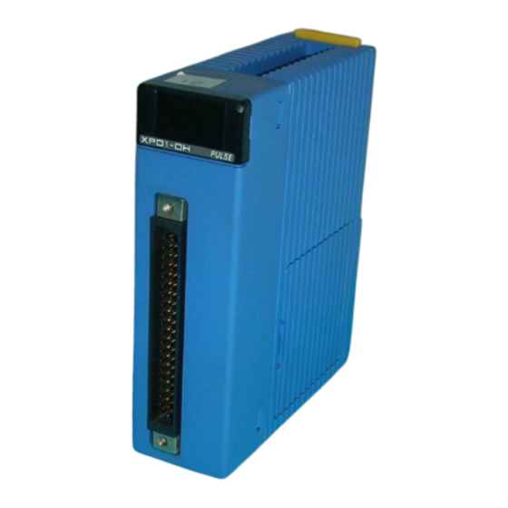
Components and Their Functions - F3XP01-0H (1 channel type) Green READY indicator : Remains lit when the internal circuitry is in normal operation. Red I/O status indicators : Work as noted below. "A" indicator : Comes on when the phase-A pulse input signal F3XP01 PULSE turns on. -
Page 27: External Connection Diagram
External Connection Diagram (F3XP02-0Hのみ) OUT2 OUT2 OUT1 OUT1 EN+ EN- EN+ EN- PST+ PST- PST+ PST- B+ B- B+ B- A+ A- A+ A- EN+ EN- EN+ EN- PST+ PST- PST+ PST- B+ B- B+ B- A+ A- A+ A-... -
Page 28: External Dimensions
External Dimensions 83.2 28.9 (Unit: mm) (Note) The above is for F3XP02-0H. IM 34M06H53-01E... -
Page 29: Configuring Function Switches On The Modules
Configuring Function Switches on the Modules Each of the counter modules is equipped with function switches on its side panel. Before the counter module is attached to the base module, the function switches need to be configured. Figure 2.2 identifies where these switches are located. Side view Front Back... -
Page 30: Configuring The Channel-1 Function Switch
2-10 Configuring the Channel-1 Function Switch The channel-1 DIP function switch is used to select between the on/off setpoints of the operating mode, counter mode, counter enable mode, external matching output mode and filter. Configure the function switch by sliding the subswitches either to the on or off position with a small, flat-blade screwdriver or other similar tool. -
Page 31: Configuring The Channel-2 Function Switch (F3Xp02-0H Module Only)
2-11 Configuring the Channel-2 Function Switch (F3XP02-0H module only) The channel-2 DIP function switch is used to select between the on/off setpoints of the operating mode, counter mode, counter enable mode and filter. Configure the function switch by sliding the subswitches either to the on or off position with a small, flat-blade screwdriver or other similar tool. -
Page 32: Attaching And Detaching Modules
2-12 Attaching and Detaching Modules Attaching/Detaching Modules Figure 2.5 shows how to attach this module to the base module. First hook the anchor slot at the bottom of the module to be attached onto the anchor pin on the bottom of the base module. -
Page 33: Attaching Modules In Intense Vibration Environments
2-13 Attaching Modules in Intense Vibration Environments If the module is used in intense vibration environments, fasten the module with a screw. Use a screw described in the table below and tighten it into the guide channel at the top of this module with a Phillips screwdriver. -
Page 34: Wiring Modules
2-14 Wiring Modules Phase-A/B Pulse Inputs When the Pulse Generator Is Open-Collector: Power supply 12V DC power supply Counter module Shielded, twisted-pair cable 24V A+ Phase-A pulse input 12V A+ 5V A+ 24V A– 12V A– Encoder 5V A– output 24V B+ Phase-B pulse input... - Page 35 2-15 When the Pulse Generator Is Source-Loaded (Voltage Output): 5V DC power supply Counter module Shielded, twisted-pair cable 24V A+ Phase-A pulse input 12V A+ 5V A+ 24V A– 12V A– 5V A– 24V B+ Phase-B pulse input 12V B+ 5V B+ 24V B–...
-
Page 36: External Preset/External Enable Inputs
2-16 External Preset/External Enable Inputs 24V DC power supply Counter module 24V PST+ External preset input 12V PST+ 5V PST+ Sensor Sensor output 24V PST– 12V PST– 5V PST– Shielded, twisted-pair cable 24V EN+ External enable input 12V EN+ 5V EN+ Sensor Sensor output... -
Page 37: External Matching Outputs
2-17 External Matching Outputs When the Counter Module Is Relay-Connected: Counter module Power supply OUT1 Relay 5-24V DC COM1 OUT2 Relay COM2 When the Counter Module Is TTL-Connected: Power supply 5V DC Pull-up resistor Counter module OUT1 Pull-up resistor COM1 OUT2... -
Page 38: Notes On Wiring
2-18 Notes on Wiring Connection to Input Terminals Separate input terminals are provided depending on the level of the signal voltage. Connecting a cable to an input terminal with the wrong voltage may result in not only a failure of the module to operate properly but also damage to the module. - Page 39 2-19 For conforming equipment incorporating the high-speed counter module to CE Marking: Use a shielded cable for conforming equipment incorporating the High-speed Counter Module to CE Marking. Remove the cable cover to expose the wire, ground and secure with an FG clamp. Remove the cover Shielded and secure with an...
- Page 40 Blank Page...
-
Page 41: Functions Of The Function Switch
Functions of the Function Switch Operation Mode There are two types of operation mode: (1) Linear mode (2) Ring mode The operation mode is set by bit number 1 of the function switch. See Section 2.3. Linear Operation In linear operation, the counter value varies between $00000000 and $FFFFFFFF ($ denotes a hexadecimal number). -
Page 42: Ring Operation
Ring Operation For ring operation, the counter value varies between $00000000 and the maximum ring value. If a down-pulse is entered when the counter value is $00000000, the counter value becomes the maximum ring value. Moreover, if an up-pulse is entered when the counter value is the maximum ring value, the counter value becomes $00000000. -
Page 43: Counter Modes
Counter Modes There are five types of counter mode: - Phase difference x 1 mode - Phase difference x 2 mode - Phase difference x 4 mode - Pulse-and-direction mode - Addition/subtraction mode The counter mode is set by bit numbers 2, 3, 4, 5 of the function switch. See Section 2.3 of this manual. -
Page 44: Phase Difference X 4 Mode
Phase Difference x 4 Mode When phase A leads phase B by 90°, it increments the counter at the rising and falling edges of phase A and phase B. When phase A lags phase B by 90°, it decrements the counter at the rising and falling edges of phase A and phase B. -
Page 45: Counter Enable/Disable
Counter Enable/Disable The module can be set to either count (counter enable) or not count (counter disable) input pulses. When the counter is disabled, the comparison operation (see Section 5.1) explained later is not performed. Table 3.2 Enable/Disable Status List Counter Counter Disable Counting operation... - Page 46 CAUTION To enter a down count during counter disable (see the figure below), reset the module using a program immediately before enabling the counter. (For more details, see Section 5.2, “Resetting the Module”.) All the registers and counter values within the module will be initialized. Perform setting again if necessary.
-
Page 47: External Matching Output Mode
External Matching Output Mode CAUTION Only the external matching output 2-point mode can be used for F3XP01-0H. External matching output 4-point mode cannot be used. There are two types of external matching output mode: external matching output 2-point mode and external matching output 4-point mode. In this module, each channel has two external matching outputs. - Page 48 Blank Page...
-
Page 49: Data Types And Settings
Data Types and Settings The input/output registers of this module are listed in Table 4.1. Data in the registers are in units of long word. Table 4.1 Input/Output Registers Ladder BASIC Data Data Type Input/output register Initial value position Read Write position Read... -
Page 50: Counter Value
Counter Value Reading the Counter Value Counter values are read from registers at the data position numbers shown in Table 4.2. Table 4.2 Data Position Number for Reading the Counter Value Channel 1 Channel 2* Ladder BASIC : Not applicable to F3XP01-0H. ... -
Page 51: Set Value
Set Value The set value is the standard value used for comparison with the counter value. Two set values (set value 1 and set value 2) can be set for channel 1 in F3XP01-0H and for channel 1 and channel 2 in F3XP02-0H, respectively. Setting is carried out by writing the set value in the register. -
Page 52: Preset Value
Preset Value Presetting means setting any arbitrary value already written in the register to the counter. This value is called the preset value. Preset values can be set for channel 1 in F3XP01-0H and for channel 1 and channel 2 in F3XP02-0H, respectively. -
Page 53: Operation Of The Module
Operation of the Module Comparison Operation The comparison operation compares the set value and the counter value and reflects the result in the input relay. As a result of the comparison, if the set value and the counter value is the same, the external matching output signal (OUT1, OUT2) turns ON. -
Page 54: Interrupt
Enable/Disable The external matching output signal can be enabled or disabled. If the set value and counter value are the same, the external matching output signal turns ON (1) if it is enabled. If disabled, the external matching output signal always remains OFF (0). -
Page 55: Reset
Reset Resetting the Module Module Reset restores all the registers and counter values of this module shown below to their initial values: - Input relay - Counter value - Set value - Maximum ring value The initial value is 0 (OFF) for input relays; $00000000 for counter values and set values, and $FFFFFFFF for maximum ring values. - Page 56 Blank Page...
-
Page 57: Reading The Counter Value, Set Value, Maximum Ring Value And Preset Value
Accessing the Module This module can be accessed either using a ladder sequence or a BASIC program. Access is via input/output registers and input/output relays of the module. 6.1 Accessing Using Ladder Application Instructions Reading the Counter Value, Set Value, Maximum Ring Value and Preset Value The Special Module Long Word Read instruction or Special Module Long Word High- Speed Read instruction given below are used for reading input/output registers. -
Page 58: Preset Value
First data position number to read……Data position number of input/output register (1 to 16). Counter value Data position 1 32 bits (Initial value $00000000) in channel 1 Counter value Data position 2 32 bits (Initial value $00000000) in channel 2 Data position 3 Not in use Data position 8... - Page 59 Writing the Counter Value, Set Value, Maximum Ring Value and Preset Value The Special Module Long-Word Write instruction or Special Module Long-Word High- Speed Write instruction are used for writing to input/output registers. The value stored in the specified data device number is stored in the set value region within this module.
-
Page 60: Related Input Relays
Related Input Relays Input relays related to this module are given in Table 6.3 Xnn Table 6.3 Input Relays Latch Input type Interrupt relay Relay status = 1 (ON) Relay status = 0 (OFF) /State Specification number type Counter value of channel 1 set value 1 X01 Counter value of channel 1 = set value 1 Latch... -
Page 61: Interrupt
Interrupt An interrupt can be generated when a OFFON change in the status of input relays X01 to X06 is detected. Sample Programs Sample program for F3XP01-0H This program sets the set value for channel 1 to 10000 and stops the counter when the counter value matches the set value. - Page 62 Sample program for F3XP02-0H This program sets the set value for channel 1 to 10000 and stops the counter when the counter value matches the set value. At the same time, it reads the counter value of channel 2. It assumes that the high speed counter module is in slot 5.
-
Page 63: Accessing Using Basic Statements
Accessing Using BASIC Statements BASIC statements shown in Table 6.5 can be used for the module. Operation is not guaranteed when BASIC statements other than those in Table 6.5 are used. Table 6.5 BASIC Statements that Can Be Used in the Module Function Statement Syntax Explanation... -
Page 64: Reading The Counter Value
Reading the Counter Value The counter value is read by specifying the slot number where the module is installed and the data position number. Data is read in units of 32 bits in the range of hexadecimal numbers $0 to $FFFFFFFF (0 to 4294967295). -
Page 65: Reading The Set Value, Maximum Ring Value And Preset Value
Reading the Set Value, Maximum Ring Value and Preset Value The set value, maximum ring value and preset value are read by specifying the slot number where the module is installed and the data position number. The data is read in units of 32 bits in the range of hexadecimal $0 to $FFFFFFFF (0 to 4294967295). -
Page 66: Writing The Set Value, Maximum Ring Value And Preset Value
6-10 Writing the Set Value, Maximum Ring Value and Preset Value The set value, ring maximum value and preset value are written by specifying the slot number where the module is installed and the data position number. Data is written in 32 bit units. Specify the data to be written as numeric, long integer variable or long integer array variable. - Page 67 6-11 LSTATUS(SL,101, L) Read-data storage varibable Slot number (See “ Declaring Use of Module” in Section 6.2.) Read data storage variable……Variable for storing the data read (Long integer variable type or long integer array variable type.) As shown in Figure 6.7 the read data is allocated to bits of one long word. 31 30 29 28 27 26 25 24 23 22 21 20 19 18 17 16 15 14 13 12 11 10 9 8 7 6 5 4 3 2 1 0 0 0 0 0 0 0 0 0 0 0 0 0 0 0 X01...
-
Page 68: Writing To Output Relays
6-12 Writing to Output Relays The output relays related to this module are given in Table 6.7. Table 6.7 Output Relays Output Register relay Operation when it is ON (1) Remarks number N Number. Y33 Enables count status for channel 1. Y34 Enables external matching output 1 for channel 1. -
Page 69: Interrupt
6-13 11 10 N=101 Y33 Y34 Y35 Y36 Y37 Y38 Y39 Y40 Y41 Y42 Y43 Y44 Y45 Y46 (Not in use) Y48 11 10 N=102 X49 (Not in use) X50 Figure 6.8 Bit Assignment for Output Relays Interrupt An interrupt can be generated when a OFFON change in the status of the input relays X01 to X06 is detected. -
Page 70: Sample Program
6-14 Sample Program This sample program sets $AAAA0000 to the set value of channel 1 and reads the input relay when the counter value matches the set value, and also resets the input relay. It assumes that the High-speed Counter module is in slot 5. !****************************************************** High speed counter module Sample... -
Page 71: Revision Information
If you have any questions, you can send an E-mail to the following address. plc_message@cs.jp.yokogawa.com plc_message@cs.jp.yokogawa.com E-mail: E-mail: ■Written by ■Written by Yokogawa Electric Corporation Yokogawa Electric Corporation ■Published by ■Published by Yokogawa Electric Corporation Yokogawa Electric Corporation 2-9-32 Nakacho, Musashino-shi, Tokyo, 180-8750, JAPAN... - Page 72 Blank Page...
Need help?
Do you have a question about the FA-M3V F3XP01-0H and is the answer not in the manual?
Questions and answers