Table of Contents
Advertisement
Quick Links
User's
Manual
Positioning Modules
(with Multi-channel Pulse Output)
Applicable Modules:
Model Code
F3YP22-0P
Positioning Module (with Multi-channel Pulse Output)
F3YP24-0P
Positioning Module (with Multi-channel Pulse Output)
F3YP28-0P
Positioning Module (with Multi-channel Pulse Output)
Yokogawa Electric Corporation
Model Name
IM 34M06H55-04E
IM 34M06H55-04E
2nd Edition
Advertisement
Table of Contents

Subscribe to Our Youtube Channel
Related Manuals for YOKOGAWA FA-M3 F3YP22-0P


Summary of Contents for YOKOGAWA FA-M3 F3YP22-0P
- Page 1 (with Multi-channel Pulse Output) IM 34M06H55-04E Applicable Modules: Model Code Model Name F3YP22-0P Positioning Module (with Multi-channel Pulse Output) F3YP24-0P Positioning Module (with Multi-channel Pulse Output) F3YP28-0P Positioning Module (with Multi-channel Pulse Output) IM 34M06H55-04E 2nd Edition Yokogawa Electric Corporation...
- Page 2 Blank Page...
-
Page 3: Applicable Product
The document number for this manual is given below. Refer to the document number in all communications, including when purchasing additional copies of this manual. Document No.: IM 34M06H55-04E IM 34M06H55-04E All Rights Reserved Copyright © 2013, Yokogawa Electric Corporation... -
Page 4: Precautions
- Every effort has been made to ensure accuracy in the preparation of this manual. However, should any errors or omissions come to the attention of the user, please contact the nearest Yokogawa Electric representative or sales office. Safety Symbols - ”Handle with care.”... - Page 5 WARRANTY that is provided separately. - Yokogawa Electric assumes no liability to any party for any loss or damage, direct or indirect, caused by the use or any unpredictable defect of the product.
- Page 6 Software Supplied by the Company - Yokogawa Electric makes no other warranties expressed or implied except as provided in its warranty clause for software supplied by the company. - Use the software with one computer only. You must purchase another copy of the software for use with each additional computer.
- Page 7 General Requirements for Using the FA-M3 / e-RT3 Controller Set the product in a location that fulfills the following requirements: - INDOOR USE ONLY - This product is an open equipment. The product must be installed in a metallic panel enclosure with an impact rating IK08 or more.
- Page 8 Configure and route cables with noise control considerations: - Perform installation and wiring that segregates system parts that may likely become noise sources and system parts that are susceptible to noise. Segregation can be achieved by measures such as segregating by distance, installing a filter or segregating the grounding system.
- Page 9 Euroweg 2, 3825 HD Amersfoort, The Netherlands In relation to UKCA marking, the importer for this product into Great Britain market via the YOKOGAWA sales channel is: - Yokogawa United Kingdom Limited, Stuart Road Manor Park Runcorn, WA7 1TR, United Kingdom. ...
- Page 10 viii General Requirements for Using the FA-M3 Slave Units (TAH Series) C onnect YHLS cable to SHIELD terminal: - Connect the DRAIN line of the YHLS cable to the SHIELD terminal of the YHLS master module securely. Failing to do so may affect the performance of the YHLS system.
- Page 11 Batteries the user cannot remove Dispose the battery together with this product. When you dispose this product in the EEA and UK, contact your local Yokogawa office in the EEA and/or UK respectively. Do not dispose them as domestic household waste.
-
Page 12: Introduction
Introduction Overview of the Manual This user's manual explains the specifications and operation of the positioning modules (multi-channel pulse output) F3YP22-0P, F3YP24-0P, and F3YP28-0P. Other Manuals ● For information on the specifications, configuration*1, installation, wiring, trial operation, maintenance and inspection of the FA-M3, as well as information on the system-wide limitation of module installation, refer to: Refer to the relevant product manuals for specifications except for power supply modules, base modules,... -
Page 13: Copyrights And Trademarks
Copyrights The copyright of the programs and online manuals contained in the software medium of the Software Product shall remain in YOKOGAWA. You are allowed to print the required pages of the online manuals for the purposes of using or operating the Product; however, reprinting or reproducing the entire document is strictly prohibited by the Copyright Law. - Page 14 Blank Page...
-
Page 15: Table Of Contents
TOC-1 Positioning Modules (with Multi-channel Pulse Output) IM 34M06H55-04E CONTENTS Applicable Product ....................i Precautions ......................ii Introduction ......................x Copyrights and Trademarks ................xi Overview ....................1-1 Features ......................1-1 Concept of Position Control ................1-2 Counter Functions ....................1-3 Specifications .................. - Page 16 TOC-2 Speed Change Operation ................... 3-9 Counter Functions .................... 3-10 3.6.1 Counter Coincidence Detection ............3-10 3.6.2 Counter Zone Coincidence Detection ..........3-10 Trigger Functions ....................3-11 Save to/Initialize Flash Memory ................ 3-12 Preparing for Operation ................ 4-1 Input/Output Relays ................5-1 Input Relays ......................
- Page 17 TOC-3 Origin Search ....................8-20 8.6.1 Manual Origin Search ............... 8-20 8.6.2 Automatic Origin Search ..............8-27 Set Current Position ..................8-32 Positioning Operation ..................8-35 8.8.1 Start Positioning ................8-35 8.8.2 Start Positioning with Position Data Record ........8-39 Target Position Change Operation ..............
- Page 18 12.2.8 Counter Contact Output ..............12-13 12.3 Examples of Connections to Motors/Drivers ..........12-14 12.3.1 Example of Connection to Yokogawa Electric Corporation Servo Amp ......................12-15 12.3.2 Example of Connection to Yaskawa Electric Corporation Servo Amp ....................... 12-16 12.3.3 Example of Connection to Oriental Motor Stepping Motor .....
- Page 19 TOC-5 Appx. 3.2 Output relay .................... Appx. 3-3 Appendix 4 List of Parameters/Statuses ..........Appx. 4-1 Appx. 4.1 Registered Parameter ................Appx. 4-2 Appx. 4.2 Command Parameters ................Appx. 4-4 Appx. 4.3 List of Position Data Records ..............Appx. 4-5 Appx. 4.4 List of Statuses for Each Axis/Common Statuses for All Axes ....Appx. 4-6 Appx.
- Page 20 Blank Page...
-
Page 21: Overview
Overview Models F3YP22-0P, F3YP24-0P, and F3YP28-0P are advanced positioning modules (hereinafter referred to as the module or positioning module) used to control servo drivers and thereby the speed and position of stepper motors. Driven by commands from the CPU module of the FA-M3 controller, the positioning module generates paths for positioning and outputs positioning command values in the form of pulse trains. -
Page 22: Concept Of Position Control
Concept of Position Control The positioning module generates a position control path according to commands (with specified target positions, speeds, acceleration/deceleration time, etc.) from the CPU module and outputs positioning command values in the form of pulse trains. The number of output pulses determines the angle through which a motor rotates and the frequency of output pulses determines the speed at which a motor rotates. -
Page 23: Counter Functions
WARNING An external emergency stop circuit should be built in, according to the motor manufacturer's recommendations, for turning off the power supply and stopping the motor immediately if it operates in an unexpected manner due to machine fault or misoperation. CAUTION When controlling a servomotor with the positioning module, choose a position- control servo driver. - Page 24 Blank Page...
-
Page 25: Specifications
Specifications Model and Suffix Codes Table 2.1 Model and Suffix Codes Suffix Style Option Model Description Code Code Code 2-axis control, 7.996 Mpps max. (for servomotor) or 1.999 Mpps max. (for stepper motor) F3YP22 ……… ……… One counter channel for encoder input, 8 Mpps max. Position control/speed control/switching between speed and position control, direct operation/position data record operation 4-axis control, 7.996 Mpps max. -
Page 26: General Specifications
General Specifications Table 2.2 General Specifications Specifications Item F3YP22-0P F3YP24-0P F3YP28-0P Control Number of controlled axes Control method Open-loop control with positioning command pulse output Pulse output method RS-422A compliant differential line driver (ISL32172E equivalent) Pulse type selectable for each axis: CW/CCW , travel/direction , and phase A/B Output pulse rates - Using a servomotor - Using a stepper motor... -
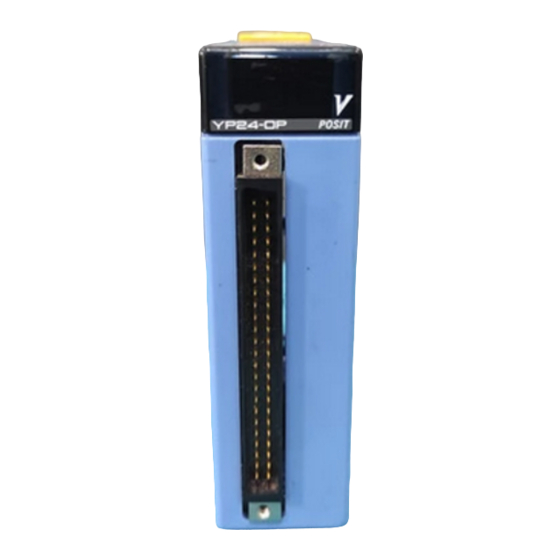
Page 27: Components And Functions
Components and Functions F3YP22-0P (with two axes), F3YP24-0P (with four axes) F3YP28-0P (with eight axes) RDY indicator: Lit when the internal circuitry is functioning normally YP28-0P POSIT ERR indicator: Lit when an error occurs Connector for axes 1 to 4 (48P): Connector for axes 5 to 8 (48P): Connects to external I/O devices such as servo motors and limit switches... -
Page 28: External Dimensions
External Dimensions Unit: mm 28.9 83.2 Note: The above diagram is for the F3YP28-0P module. Figure 2.2 External Dimensions Diagram Attachment Dimensions This module requires space for the wiring of the connector for counters. D (mm) Min. space 100 min Figure 2.3 Attaching the Connector for Counters IM 34M06H55-04E... -
Page 29: Applicable External Interface Connectors
Applicable External Interface Connectors Connectors for external I/O devices OTAX Corporation Connection Applicable Connector Remarks Soldered N361J048AU connector Purchase the N360C048B connector cover desired connector kit separately. Crimp-on N363J048 housing N363JAU contacts N360C048B connector cover Pressure-welded N367J048AUF FUJITSU COMPONENT LIMITED Connection Applicable Connector Remarks... -
Page 30: Terminal Assignments And Connections
Terminal Assignments and Connections For details on the external connection signals, refer to Chapter 12, "Connections and Wiring." Connectors for external I/O devices 24b Axis 4 Z-phase input (-) 24a Axis 2 Z-phase input (-) 24b Axis 8 Z-phase input (-) 24a Axis 6 Z-phase input (-) 23b Axis 4 Z-phase input (+) 23a Axis 2 Z-phase input (+) - Page 31 Connectors for counters Counter input A (+) Counter contact output 1 External power supply 24 Counter input A (-) Vin (GND) Counter input B (+) Counter contact output 2 External power supply 24 Counter input B (-) Counter Z-phase input (+) Counter contact input 1 Counter Z-phase input (-) Counter contact input 2...
- Page 32 Blank Page...
-
Page 33: Function Overview
Function Overview This chapter explains the major functions of the positioning module. Position Control 3.1.1 Positioning Operation Positioning operation to a specified target position is performed according to the specified target speed, acceleration time, and deceleration time. You can specify an absolute position or incremental position as the target position. -
Page 34: Multi-Axis Linear Interpolated Operation
Table 3.1 Position Data Record Target Target Accel/ Target Startup Record Acceleration Deceleration Position Position Decel Speed Speed Time (ms) Time (ms) Mode (pulses) Mode (pulse/s) (pulse/s) 2,000 131,072 2,000 100,000 5,000 3.1.3 Multi-axis Linear Interpolated Operation To perform a linear-interpolated operation, set the target position, target speed, acceleration time, and deceleration time, and execute a Start Positioning command (or a Start Positioning with Position Data Record command) simultaneously for all axes to be interpolated. -
Page 35: Positioning Operation With Resetting Current Position
3.1.5 Positioning Operation with Resetting Current Position You can perform positioning operation after setting the current position to "0". By executing a single command, you can execute a Set Current Position command to write "0" for the current position and then execute a Start Positioning command. This operation is useful for control that repeats an operation in a single direction because it can avoid an overflow error that occurs if the operating range (32 bit) of the positioning module is exceeded. -
Page 36: Speed Control
Speed Control 3.2.1 Speed Control Operation This operation moves an axis continuously in a single direction according to the specified target speed, acceleration time, and deceleration time. You can set an automatic trapezoidal or automatic S-shape acceleration/deceleration as an acceleration/deceleration curve. For each curve, you can set the acceleration time and deceleration time. -
Page 37: Origin Search
Origin Search There are two ways to perform origin search: automatic and manual. In automatic origin search, the origin search behavior is defined by registered parameters. In manual origin search, the origin search behavior is arbitrarily defined by an application program. 3.3.1 Automatic Origin Search Before initiating automatic origin search, you must first set the AOS Mode and other... - Page 38 - If the axis is right on the reverse limit switch at origin search start Figure 3.10 Automatic Origin Search (mode 0, reverse direction search) Automatic Origin Search (1: Origin input is not used) - If the axis is away from the reverse limit switch at origin search start - If the axis is right on the reverse limit switch at origin search start Figure 3.11 Automatic Origin Search (mode 1, reverse direction search)
- Page 39 3.3.2 Manual Origin Search In manual origin search, the module searches for the origin according to the command parameter values as it detects changes in external contact inputs. When the required change is detected, it either stops or shifts to Z-phase search. If configured to perform Z-phase search, the module counts the number of Z-phase pulses defined by the Z-phase Search Count parameter, and then stops the axis immediately.
- Page 40 Manual Control There are two types of manual control: jog and manual pulse generator mode. In both jog and manual pulse generator mode, you can specify whether to stop the operation with an error (a pulse overflow error) or continue it as unlimited rotation, if the operating range (32 bit) of the positioning module is exceeded.
-
Page 41: Speed Change Operation
Speed Change Operation You can change the operation speed during a positioning operation, speed control operation, or jog operation. The following restrictions apply to changing the speed during an operation. The speed cannot be changed during a positioning operation if the speed change prevents the axis from stopping at the target position during an acceleration, deceleration, speed change, or target position change operation. -
Page 42: Counter Functions
3-10 Counter Functions The module has a counter input channel that allows input at up to 8 Mpps, three high- speed contact inputs for a counter, and two high-speed contact outputs for a counter. General counter functions, such as the counter enable/disable control function, counter latch function (two channels), and counter preset function, are available. -
Page 43: Trigger Functions
3-11 Trigger Functions You can specify a trigger condition for a positioning operation, speed control operation, or decelerate and stop operation. You must issue a command with a trigger beforehand in the same procedure as the standard command, and when the trigger occurs, the specified operation starts immediately. -
Page 44: Save To/Initialize Flash Memory
3-12 Save to/Initialize Flash Memory Save to Flash Memory After specifying parameters, you can save the parameters to the flash memory in this module. At power up or system reset, the content of the flash memory is automatically reloaded to the parameters. -
Page 45: Preparing For Operation
Preparing for Operation Figure 4.1 shows the procedure flowchart for operation preparation. For details on the task in each box, refer to the table on the next page. Figure 4.1 Flowchart for Operation Preparation IM 34M06H55-04E... -
Page 46: Input/Output Relays
Table 4.1 Description and Reference for Each Task Task Description See Also Design the system after understanding the functions and - 1. Overview usage of the positioning module and external devices. - 2. Specification - 3. Function Overview Mount the positioning module to the base module. - 12.1 Attaching and Detaching Modules Install and set up external devices such as - User's manuals for external devices... - Page 47 Input/Output Relays The positioning module has 32 output relays and 32 input relays for interfacing to the FA-M3 CPU module. CAUTION - For the F3YP22-0P module, NEVER set the output relays for axes 3 to 8; moreover, input relays for axes 3 to 8 have no meaning. - For the F3YP24-0P module, NEVER set the output relays for axes 5 to 8;...
-
Page 48: Input Relays
Input Relays Table 5.1 lists the input relays available in the positioning module. An interrupt signal can be sent to the CPU module by changing the state of an input relay from off to on. Note that "" in the table represents the number of the FA-M3 slot where the positioning module is installed. - Page 49 Input Relay Signal Description Relationship with Other Relays X17 AX1 Error Detected Turns on when an error occurs on axis 1. X18 AX2 Error Detected Turns on when an error occurs on axis 2. X19 AX3 Error Detected Turns on when an error occurs on axis 3. X20 AX4 Error Detected Turns on when an error occurs on axis 4.
-
Page 50: Output Relays
Output Relays Table 5.2 lists the output relays available in the positioning module. Note that "" in the table represents the number of the FA-M3 slot where the positioning module is installed. Table 5.2 List of Output Relays Output Relay Signal Description Relationship with Other Relays... -
Page 51: Behavior Of Input/Output Relays
Behavior of Input/Output Relays Input Relays Execute Command ACK Relay (X01 to X08) This relay turns on if the Execute Command relay (Y33 to Y40) is turned on and a command has been successfully executed. It does not turn on if the operation has not been successfully executed (due to an error, etc.). - Page 52 Output Relays Execute Command Relay (Y33 to Y40) Turning on one of these relays starts an operation specified by a command code stored in the command parameter for each axis. When the operation specified by the command code has been successfully executed, the Execute Command ACK relay (X01 to X08) turns on.
-
Page 53: Positioning Parameters And Statuses
Positioning Parameters and Statuses Table 6.1 shows the layout of the parameter area and status area for the positioning module. For details, refer to Sections 6.1 and 6.2. Table 6.1 Layout of the Parameter and Status Areas Data Position No. Description (Word Basis) 0001 to 0040... - Page 54 Reading and Writing Two-word Data Among the positioning parameters and statuses given in Tables 6.2 to 6.14, those listed with two data position numbers are two-word data. The smaller data position number contains the low-order word, and the larger data position number contains the high-order word.
-
Page 55: Parameters
Parameters 6.1.1 List of Registered Parameters At power up or system reset, the contents of the flash memory are automatically reloaded to the registered parameters. To change the settings of the registered parameters, write new parameter settings from the CPU module, and execute the Set Registered Parameters command. - Page 56 Do not set a value other than 0. (System reserved) [Factory default: 0] 0: Detect an overflow error during jogging or MPG mode 1: Do not detect an overflow error during jogging or MPG Unlimited Rotation Setting 6-12 mode [Factory default: 0] 0: Do not use Z-phase filter 1: Use at frequency of 1 Mpps or less Z-phase Setting...
-
Page 57: Description Of Registered Parameters
6.1.2 Description of Registered Parameters Speed Mode Selection [Data Range] $0000 to $0007 (bit data) [Factory default] $0000 [Data Position No.] *01 (The symbol '*' represents the axis number minus 1.) Selects the maximum output pulse speed and the units for speed and acceleration/deceleration time parameters/statuses. - Page 58 Table 6.4 List of Parameters and Statuses Handled Differently Depending on the Command Speed Unit Selection Data Position Parameter Description (Word Basis) 1 to 7,996,000 [pulse/s] *09/*10 Speed Limit 1 to 524,025,856 [(1/65536) pulse/ms] *13/*14 AOS Speed 1 1 to Speed Limit [command speed unit] Registered Parameters *15/*16...
- Page 59 Pulse Output Mode [Data Range] 0: CW/CCW pulse 1: Travel/direction 2: Phase A/B (x4) 3: Phase A/B (x2) 4: Phase A/B (x1) [Factory default] 0: CW/CCW pulse [Data Position No.] *02 (The symbol '*' represents the axis number minus 1.) Specifies the output pulse mode.
- Page 60 Motor Direction Selection [Data Range] 0: Forward movement produces CW pulse output 1: Reverse movement produces CW pulse output [Factory default] 0: Forward movement produces CW pulse output [Data Position No.] *03 (The symbol '*' represents the axis number minus 1.) Maps the sign of position data set from the CPU module to the direction of pulse output.
- Page 61 Forward Limit [Data Range] -2,147,483,648 to 2,147,483,647 [pulses] [Factory default] 2,147,483,647 [Data Position No.] *05/*06 (The symbol '*' represents the axis number minus 1.) Specifies the value for the limit on forward movement from the origin. Specifying a target position that exceeds this range and starting the system will result in an error during startup and the motor will not operate.
- Page 62 6-10 AOS Speed 1 [Data Range] 1 to Speed Limit [pulse/s] 1 to Speed Limit [(1/65536) pulse/ms] (The unit varies depending on the command speed unit selection.) [Factory default] 655,360 [(1/65536) pulse/ms] [Data Position No.] *13/*14 (The symbol '*' represents the axis number minus 1.) Specifies the high speed for automatic origin search.
- Page 63 6-11 AOS Deceleration Time [Data Range] 0 to 32,767 [Acceleration/Deceleration Time Unit] (The unit varies depending on the acceleration/deceleration time unit selection.) [Factory default] 1,000 [ms] [Data Position No.] *20 (The symbol '*' represents the axis number minus 1.) Specifies the time taken to decelerate and stop from AOS Speed 1 in an automatic origin search.
- Page 64 6-12 AOS Deviation Pulse Clear Time [Data Range] 0 to 32,767 [ms] [Factory default] 1000 [Data Position No.] *25 (The symbol '*' represents the axis number minus 1.) Specifies the duration for deviation pulse clear output after completing the origin search using Z-phase detection in an automatic origin search.
- Page 65 6-13 Z-phase Setting [Data Range] 0: Do not use Z-phase filter 1: Use at frequency of 1 Mpps or less. 2: Use at frequency of 500 Kpps or less. 3: Use at frequency of 100 Kpps or less. [Factory default] 0: Do not use Z-phase filter [Data Position No.] *30 (The symbol '*' represents the axis number minus 1.)
- Page 66 6-14 Pulse Output External Power Source Detection Setting (Emergency Stop Setting) [Data Range] 0: Do not detect errors on external power source for pulse output 1: Detect errors on external power source for pulse output [Factory default] 0: Do not detect errors on external power source for pulse output [Data Position No.] *39 (The symbol '*' represents the axis number minus 1.)
-
Page 67: Example For Setting Registered Parameters
6-15 6.1.3 Example for Setting Registered Parameters The following example shows a minimal set of registered parameters, which must be defined for controlling a motor using the positioning module. The underlined values are to be entered. Motor to Be Controlled Rated rotating speed: 3,000 rpm Encoder pulse count: 8,000 pulses per rotation CAUTION... - Page 68 6-16 - Forward Limit (*05/*06) 1000 [mm] 5 [mm/rot] 8000 [pulse/rot] = 1600000 [pulses] - Reverse Limit (*07/*08) -500 [mm] 5 [mm/rot] 8000 [pulse/rot] =-800000 [pulses] - Speed Limit (*09/*10) The maximum pulse output speed allowed by the motor is: 3,000 [rpm] ...
- Page 69 6-17 - AOS Deviation Pulse Clear Time (*25) Set this parameter to 1,000 [ms] to output the deviation pulse clear signal for 1 second. - AOS Offset (*26/*27) Set this parameter to 0 [pulse] to specify the Z-phase detection position for the origin.
-
Page 70: List Of Command Parameters
6-18 6.1.4 List of Command Parameters These are parameters to be set when executing a command. It is necessary to write all the required parameters when executing a command. Table 6.6 Command Parameters Data Position No. Parameter Description (Word Basis) Also Command Code 0 to 32,767... -
Page 71: Required Parameters For Each Command
6-19 6.1.5 Required Parameters for Each Command You must write all the required parameters before executing a command for the positioning module from the CPU module. Table 6.7 shows the required parameters for each command. Table 6.7 Required Parameters for Each Command (1/3) Command Data Position... - Page 72 6-20 Table 6.7 Required Parameters for Each Command (2/3) Command Data Position Parameter Command Code Target Position Mode/ Position Data Record No. *43/*44 Target Position Accel/Decel Mode *46/*47 Target Speed ...
- Page 73 6-21 Table 6.7 Required Parameters for Each Command (3/3) Command Data Position Parameter Command Code 1000 1001 1010 1020 1400 1401 1402 Target Position Mode/ Position Data Record No. *43/*44 Target Position Accel/Decel Mode ...
-
Page 74: Manual Origin Search
6-22 6.1.6 Description of Command Parameters Command Code [Data Range] 0 to 32,767 [Data Position No.] *41 (The symbol '*' represents the axis number minus 1.) Set the command type for command execution using the Execute Command relay. Table 6.8 List of Command Codes Command Command... - Page 75 6-23 Target Position Mode/Position Data Record No. [Data Range] In direct operation: 0: Using ABS position, 1: Using INC position In position data record operation: 1 to 10 [Position data record number] [Data Position No.] *42 (The symbol '*' represents the axis number minus 1.) Specifies how to specify a target position.
- Page 76 6-24 Acceleration Time [Data Range] 0 to 32,767 [acceleration/deceleration time unit] -1: The Acceleration Setting registered parameter is used. [Data Position No.] *48 (The symbol '*' represents the axis number minus 1.) Sets the acceleration time to reach the target speed from the startup speed. For a speed change operation, set acceleration/deceleration time.
- Page 77 6-25 Startup Speed [Data Range] 0 to target speed [command speed unit] [Data Position No.] *50/*51 (The symbol '*' represents the axis number minus 1.) This parameter is valid only when the Accel/Decel Mode is "0: Trapezoidal acceleration/deceleration (With startup speed)". This parameter specifies the startup speed at the beginning of the positioning operation and the speed just before stopping when the positioning is completed.
- Page 78 6-26 Z-phase Search Count [Data Range] 0 to 32,767 [pulses] [Data Position No.] *55 (The symbol '*' represents the axis number minus 1.) Specifies how many Z-phase inputs must be detected before an origin can be found during manual origin search. When "0" is set, the position where Z-phase search is started (the position where the origin input or forward/reverse limit input becomes off without any Z-phase being detected) is used as the Z-phase detection position.
-
Page 79: Trigger Setting
6-27 Manual Pulse Generator M Value [Data Range] -32,768 to 32,767 [Data Position No.] *60 (The symbol '*' represents the axis number minus 1.) Sets the M value used in manual pulse generator mode. Manual Pulse Generator N Value [Data Range] 1 to 32,767 [Data Position No.]... - Page 80 6-28 Trigger Axis Setting [Data Range] 0, 1 to 8 axes [Data Position No.] *64 (The symbol '*' represents the axis number minus 1.) Specifies a target axis used as a trigger input when "software trigger" or "Positioning Completed input relay trigger" is selected for the Trigger Setting parameter. For a software trigger, when this parameter is set to "0", an axis from which the command is issued is used as the target axis.
- Page 81 6-29 Counter Zone Coincidence Trigger Setting [Data Range] $0000 to $8000 (Select only one of the bits.) [Data Position No.] *67 (The symbol '*' represents the axis number minus 1.) Specifies a counter bit status used as a trigger input when "counter zone coincidence trigger"...
- Page 82 6-30 6.1.7 List of Position Data Records Table 6.10 Position Data Record (Table Number 1 for Axis 1) Data Position No. Parameter Description (Word Basis) Also 0: Using ABS position, 1: Using INC position 1001 Target Position Mode 6-31 [Factory default: 0] Reverse limit to forward limit [pulses] 1002/1003 Target Position...
- Page 83 6-31 6.1.8 Description of Position Data Records Target Position Mode [Data Range] 0: Using ABS position, 1: Using INC position Specifies how to specify a target position. In the absolute position mode, the specified target position represents a new target position regardless of the current position.
- Page 84 6-32 Startup Speed [Data Range] 0 to target speed [command speed unit] This parameter is valid only when the Accel/Decel Mode is "0: Trapezoidal acceleration/deceleration (With startup speed)". This parameter specifies the startup speed at the beginning of the positioning operation and the speed just before stopping when the positioning is completed.
- Page 85 6-33 Statuses Statuses refer to data which the CPU module reads from the positioning module. You can check the state of the positioning module using these statuses and input relays. Only for specific statuses, by using a long-word-basis READ instruction (READ L instruction), concurrency of the high-order word and low-order word of two-word data is assured.
- Page 86 6-34 6.2.1 List of Statuses for Each Axis/List of Common Statuses for All Axes Table 6.12 List of Statuses for Each Axis (Word Basis) Data Position Status Description Also (Word Basis) *81/*82 Target Position Status -2,147,483,648 to 2,147,483,647 [pulses] 6-35 *83/*84 Current Position Status -2,147,483,648 to 2,147,483,647 [pulses]...
- Page 87 6-35 Table 6.14 List of Common Statuses for All Axes Data Position No. Parameter Description (Word Basis) Also 0981 Module Information "F3" 6-38 0982 Module Information "YP" 6-38 0983 Module Information "22", "24", or "28" 6-38 0984 Module Information "0P" 6-38 0985 Module Information...
- Page 88 6-36 Contact Input Status [Data Position No.] *87 (The symbol '*' represents the axis number minus 1.) [Data Range] $0000 to $000F Used to read the state of the external contact inputs and the encoder Z-phase input. The state of each contact is stored as 1 bit (0: off; 1: on). 15 14 13 12 11 10 9 8 7 6 5 4 3 2 1 0 0 0 0 0 0 0 0 0 0 0 0 0 X X X X |...
- Page 89 6-37 Extended Status [Data Position No.] *91 (The symbol '*' represents the axis number minus 1.) [Data Range] $0000 to $133F (bit data) Used to read operation information that represents the positioning operation state of an axis on a bit basis. When the axis is in a particular operation, the corresponding bit is set to '1'.
- Page 90 6-38 Module Information [Data Position No.] 0981 to 0988 [Data Range] Module type: "F3YP220P", "F3YP240P", or "F3YP280P" Revision: "RV" Used to read the module type and revision as module information. Pulse Output External 24V Power Source [Data Position No.] 0990 [Data Range] 0: The external 24V power source for pulse outputs is off.
- Page 91 Counter Parameters and Statuses Table 7.1 shows the layout of the parameter area and status area for the positioning module. For details, refer to Sections 7.1 and 7.2. Table 7.1 Layout of the Parameter and Status Areas Data Position No. Description (Word Basis) 0001 to 0040...
- Page 92 Reading and Writing Two-word Data The counter parameters/statuses in Tables 7.2, 7.4 and 7.7 are two-word data (long- word data). The smaller data position number contains the low-order word, and the larger data position number contains the high-order word. When a WRITE, WRITE L, READ, or READ L instruction is used for data access from a CPU program, the data position number varies depending on the instruction used.
- Page 93 Counter Parameters 7.1.1 List of Counter Registered Parameters At power up or system reset, the contents of the flash memory are automatically reloaded to the counter registered parameters. To change the settings of the counter registered parameters, write new parameter settings from the CPU module, and then write '1' to the Counter Registered Parameters Request parameter.
- Page 94 $00000000 or greater (bit data) (This parameter specifies a status to be assigned to the 823/824 Counter Input Relay 1 Layout 7-13 counter input relay 1.) [Factory default: 0] $00000000 or greater (bit data) (This parameter specifies a status to be assigned to the 825/826 Counter Input Relay 2 Layout 7-14...
- Page 95 Figure 7.4 Counter Count Mode: CW/CCW Pulse Figure 7.5 Counter Count Mode: Travel/Direction Counter Filter Setting [Data Range] 0: Do not use filter 1: Use at frequency of 1 Mpps or less. 2: Use at frequency of 500 Kpps or less. 3: Use at frequency of 100 Kpps or less.
- Page 96 Preset Ring Counter Value [Data Range] 1 to 2,147,483,647 [pulses] [Factory default] 2,147,483,647 [pulses] [Data Position No.] 404 (Long-word address) Specifies the maximum value of the ring counter when "1: Ring counter (0 to the Preset Ring Counter Value)" is specified for Counter Action Mode Setting. The ring counter counts from 0 to the Preset Ring Counter Value.
- Page 97 Counter Z-phase Input Setting [Data Range] $00000000 or greater (bit data) [Factory default] $00000000 [Data Position No.] 406 (Long-word address) Specifies the counter Z-phase input filter setting as bit data. Also specify this setting when using the Z-phase input wired to the Z-phase input for an axis as a counter Z- phase input.
- Page 98 Counter Contact Z-phase Input Function Layout [Data Range] $00000000 or greater (bit data) [Factory default] $00000000 [Data Position No.] 407 (Long-word address) Specifies the Counter Contact Input 1 to 3, Z-phase Input, Counter Enable, Counter Preset, CNT Latched Request functions. When you assign a function, select a contact and set the relevant bit to "1".
- Page 99 31 30 29 28 27 26 25 24 23 22 21 20 19 18 17 16 X X X X X X X X X X X X X X X X | | | | | | | | | | | | | | | | CNT latched request 1 |...
- Page 100 7-10 Counter Contact Output 1 Layout [Data Range] $00000000 or greater (bit data) [Factory default] $00000000 [Data Position No.] 408 (Long-word address) Selects the function assigned to Counter Contact Output 1. Selects a bit assigned to the contact output 1 from the counter bit status. If the bit status set to 1 becomes 1, the counter contact output turns ON.
- Page 101 7-11 Counter Coincidence Direction Setting [Data Range] $00000000 or greater (bit data) [Factory default] $00000000 [Data Position No.] 410 (Long-word address) Specifies the counter coincidence detection method. If no direction is specified, a counter coincidence occurs when Counter Current Position Status changes and matches Counter Coincidence Value.
- Page 102 7-12 Counter Input Relay Setting [Data Range] 0: Counter Input Relay Not In Use 1: Counter Input Relay in Use [Factory default] 0: Counter Input Relay Not In Use [Data Position No.] 411 (Long-word address) Specify this setting when using counter input relay when using F3YP28-0P. If you specify "1: Counter Input Relay in Use ", you can use four input relays shown in Table 7.3 as counter input relays.
- Page 103 7-13 Counter Input Relay 1 Layout [Data Range] $00000000 or greater (bit data) [Factory default] $00000000 [Data Position No.] 412 (Long-word address) Specifies a bit assigned to the counter input relay 1 from the counter bit status. Set the relevant bit to 1.
- Page 104 7-14 Counter Input Relay 2 to 4 Layout [Data Range] $00000000 or greater (bit data) [Factory default] $00000000 [Data Position No.] Counter Input Relay 2, 413 (Long-word address) [Data Position No.] Counter Input Relay 3, 414 (Long-word address) [Data Position No.] Counter Input Relay 4, 415 (Long-word address) Specifies the counter bit status assigned to the counter input relays 2 to 4 in the same way as counter input relay 1.
- Page 105 7-15 7.1.3 Example of Setting Counter Registered Parameters The following example shows a minimal set of counter registered parameters, which must be defined for controlling a counter using the positioning module. The underlined values are to be entered. Setting Items Counter Input: Phase A/B input (x1) Counter input frequency: 1 M pulse/s or less...
- Page 106 7-16 - Counter Z-phase Input Setting (406, long-word address) Set this parameter to $00000001 to use the Z-phase input connected to the connector for the counter and to use the module at a frequency of 1 Mpps or less. (Decimal notation: 1, hexadecimal notation: $00000001, binary notation: 0000_0000_0000_0000_0000_0000_0000_0001)...
- Page 107 7-17 - Counter Input Relay 4 Layout (415, long-word address) Set this parameter to $00000400 to set the bit corresponding to counter contact input 3 of Counter Bit Status to "1". (Decimal notation: 1024, hexadecimal notation: $00000400, binary notation: 0000_0000_0000_0000_0000_0100_0000_0000) IM 34M06H55-04E...
- Page 108 7-18 7.1.4 List of Counter Control Parameters Table 7.4 List of Counter Control Parameters Data Position No. Long-word Word Parameter Description Also Basis Basis Requests to register the counter registered parameters. Writing "1" to this parameter performs the request to Counter Registered 847/848 register the counter registered parameters.
- Page 109 7-19 7.1.5 Description of Counter Control Parameters Counter Registered Parameters Request [Data Range] 1: Write this value to request to register the counter registered parameters. [Data Position No.] 424 (Long-word address) Writing "1" to this parameter performs the request to register the counter registered parameters.
-
Page 110: Counter Enable/Disable
7-20 Counter Enable Control [Data Range] $00000000 or greater (bit data) [Default] $00000000 [Data Position No.] 426 (Long-word address) Specifies the counter enable/disable control by a program and the debug mode of Counter Bit Status. The setting is applied immediately when a value is written to this parameter. - Page 111 7-21 Counter Contact Output 1 Control [Data Range] $00000000 or greater (bit data) [Default] $00000000 [Data Position No.] 427 (Long-word address) Specifies whether to enable or disable counter contact output 1 and the forced on/off setting of counter contact output 1. The setting is applied immediately when a value is written to this parameter.
- Page 112 7-22 Counter Contact Output 2 Control [Data Range] $00000000 or greater (bit data) [Default] $00000000 [Data Position No.] 428 (Long-word address) Specifies whether to enable or disable counter contact output 2 and the forced on/off setting of counter contact output 2. The setting is applied immediately when a value is written to this parameter.
- Page 113 7-23 Counter Zone N Lower Limit (N = 1 to 16) [Data Range] -2,147,483,648 to 2,147,483,647 [pulses] [Factory default] [Data Position No.] 433 or greater (Long-word address) Specifies the lower limit value compared with the Counter Current Position Status for Counter Zone Coincidence.
- Page 114 7-24 Counter Statuses Counter statuses refer to data which the CPU module reads from the positioning module. You can check the state of the counter using these statuses. CAUTION When a word-basis READ instruction is used from the CPU module to read two-word data, concurrency of the high-order word and low-order word of two-word data is not assured due to conflicts between the timing of reading from the CPU module and the data update period of the positioning module.
- Page 115 7-25 7.2.2 Description of Counter Statuses Counter Bit Status [Data Position No.] 417 (Long-word address) [Data Range] $00000000 or greater Used to read the operation state of the counter as bit data. Some Counter Bit Status items can be assigned to a counter contact output, counter input relay, or a trigger condition for a positioning operation.
- Page 116 7-26 - Counter coincidence detection 1/2 (latch type) These bits are "1" when Preset Counter Coincidence Value 1 or Preset Counter Coincidence Value 2 is the same as Counter Current Position Status. Because these are latch type bits, to clear the latch, write "1: Counter Coincidence Detection 1 Latch Clear Request"...
- Page 117 7-27 Counter Current Position Status [Data Position No.] 418 (Long-word address) [Data Range] -2,147,483,648 to 2,147,483,647 [pulses] Used to read the current position of the counter. You can also modify Counter Current Position Status by writing a value from the CPU module.
- Page 118 Blank Page...
- Page 119 Positioning Programs This chapter describes the function, usage, and note of each command with one or more sample programs of the command. The sample programs shown in this chapter assume the following: - The positioning module is installed in slot 3 (slot #003) of the main unit. - When only one axis is used in the example, it is axis 1.
- Page 120 Operation Procedure Figure 8.1 shows an operation procedure flowchart for a typical positioning operation. For details, refer to Sections 8.2 through 8.17. When you use a certain function such as a jog operation or request to stop immediately, the procedure is different from Figure 8.1 and specific input/output relays are used. Figure 8.1 Operation Procedure Flowchart for a Direct Operation IM 34M06H55-04E...
- Page 121 Read Parameters/Statuses Function This operation reads parameters and statuses in the module. Usage Command Parameters No command parameters need to be set. Command Acceptance Conditions This operation is always accepted. Procedure (1) Read parameters and statuses of the module from the CPU module. For details on how to access the module from the CPU, see Chapter 10, "Accessing Modules."...
- Page 122 Sample Program 1 Description This sample program reads all axis statuses of the module installed in slot 3. (This program performs word-basis access. Concurrency of the high-order word and low-order word of two-word data is not assured.) List of Devices Table 8.1 List of Devices Used by the Sample Program for Reading Parameters/Statuses Device...
- Page 123 Set Registered Parameters Function This command sets the registered parameters. Usage Command Parameters Table 8.3 shows the required parameters for this command. : Mandatory parameters. : Mandatory if the command is to be executed in the Positioning Completed status. : Mandatory depending on the values of other parameters.
- Page 124 Note - The registered parameters set using the Set Registered Parameters command are cleared at power off. Execute the Save to Flash Memory command to save parameter data if required. Even if registered parameters are not saved to the flash memory, they can be used by executing the Set Registered Parameters command each time the module is powered on.
- Page 125 Program Code IM 34M06H55-04E...
- Page 126 Figure 8.4 Sample Program for the Set Registered Parameters Command Timing Chart Figure 8.5 Timing Chart for the Set Registered Parameters Command IM 34M06H55-04E...
- Page 127 Reset Error Function This command clears the error status (state where the [Error Detected] input relay is on) of an axis. However, it cannot be used to clear a registered parameter setting error. Usage Command Parameters Table 8.6 shows the required parameters for this command. : Mandatory parameters.
- Page 128 8-10 Sample Program Description This sample program clears an error on axis 1 of the positioning module installed in slot List of Devices Table 8.8 List of Devices Used in the Sample Program for the Reset Error Command Device Name Data...
- Page 129 8-11 Manual Control You can use a jog or manual pulse generator operation to operate a motor manually. This section describes the details of jog commands and the Start MPG Mode command. 8.5.1 Function While the [Forward Jog] output relay or the [Reverse Jog] output relay is on, the motor rotates in the forward or reverse direction, respectively.
- Page 130 8-12 Usage Command Parameters Table 8.9 shows the required parameters for this command. : Mandatory parameters. : Mandatory if the command is to be executed in the Positioning Completed status. : Mandatory depending on the values of other parameters. Table 8.9 Required Parameters for Jog Commands Data Position No.
- Page 131 8-13 Note - Executing a Decelerate and Stop command during a jog operation is not allowed and will generate a warning. To stop a jog operation, turn off the [Forward (Reverse) Jog] output relay, or turn on the [Stop Immediately] output relay. - The setting values of the Forward/Reverse Limit registered parameters are ignored during a jog operation.
- Page 132 8-14 Program Code Figure 8.10 Sample Program for a Jog Operation Timing Chart Figure 8.11 Timing Chart for a Jog Operation IM 34M06H55-04E...
- Page 133 8-15 8.5.2 Manual Pulse Generator Mode Function In manual pulse generator mode, you can operate a motor using a manual pulse generator. Manual pulse generator mode continues until a Stop MPG Mode command is executed, an error occurs, or the [Stop Immediately] output relay is turned from off to on. - The ratio of the number of counter input pulses and the number of counter output pulses can be specified by using the ratio of the Manual Pulse Generator M Value and Manual Pulse Generator N Value command parameters.
- Page 134 8-16 Usage Command Parameters Table 8.12 shows the required parameters for this command. : Mandatory parameters. : Mandatory if the command is to be executed in the Positioning Completed status. : Mandatory depending on the values of other parameters. Table 8.12 Required Parameters for the Start/Stop MPG Mode Command Data Position No.
- Page 135 8-17 (7) Turn on the [Execute Command] output relay for the command axis. (8) When the command is successfully executed, the [Execute Command ACK] input relay turns on. Turn off the [Execute Command] output relay after confirming that the [Execute Command ACK] input relay has turned on. (9) The [Positioning Completed] input relay turns on when manual pulse generator mode is deactivated.
- Page 136 8-18 Sample Program Description This sample program starts manual pulse generator mode for axis 1 of the module installed in slot 3. List of Devices Table 8.15 List of Devices Used in the Sample Program for the Start MPG Mode Command Device Name Data...
- Page 137 8-19 Timing Chart Figure 8.14 Timing Chart for the Start MPG Mode Command IM 34M06H55-04E...
- Page 138 8-20 Origin Search There are two ways to perform origin search: automatic and manual. In automatic origin search, the origin search behavior is defined by registered parameters. In manual origin search, the origin search behavior is arbitrarily defined by an application program. This section describes the details of the Automatic Origin Search command and the Manual Origin Search command.
- Page 139 8-21 Origin Search Mode The Origin Search Mode parameter uses bit combination data to specify the operation to be performed when a specific edge is detected for each of the three external contact inputs related to manual origin search. You can specify one of four 2-bit combinations for each rising/falling edge of an external contact input.
- Page 140 8-22 Usage Command Parameters Table 8.16 shows the required parameters for this command. : Mandatory parameters. : Mandatory if the command is to be executed in the Positioning Completed status. : Mandatory depending on the values of other parameters. Table 8.16 Required Parameters for the Manual Origin Search Command Data Position No.
- Page 141 8-23 (5) Confirm the state of the origin search by checking Origin Search Status. If the value of Origin Search Status is "0", the origin search has been completed following a successful Z-phase search. Note - A manual origin search operation ends when a specified external contact input is detected and the axis is stopped.
- Page 142 8-24 List of Devices Table 8.18 List of Devices Used in the Sample Program for the Manual Origin Search Command Device Name Data /D00041 Command Code 2: Manual Origin Search command /D00046/D00047 Target Speed 80,000(pulse/s) /D00048 Acceleration Time 500(ms) /D00049 Deceleration Time 500(ms)
- Page 143 8-25 Program Code Figure 8.16 Sample Program for the Manual Origin Search Command IM 34M06H55-04E...
- Page 144 8-26 Timing Chart Figure 8.17 Timing Chart for the Manual Origin Search Command IM 34M06H55-04E...
- Page 145 8-27 8.6.2 Automatic Origin Search Function This command performs an origin search operation according to the origin search method specified by registered parameters. - Automatic origin search uses one of two operation modes depending on the setting of the AOS Mode registered parameter. One mode uses the origin switch input, whilst the other mode does not use the origin switch input but uses the forward/reverse limit switch input instead.
- Page 146 8-28 If the axis is between the origin and the reverse limit switch at origin search start If the axis is right on the reverse limit switch at origin search start Figure 8.18 Automatic Origin Search (Mode 0, Reverse Direction Search) ...
- Page 147 8-29 Usage Command Parameters Table 8.19 shows the required parameters for this command. : Mandatory parameters. : Mandatory if the command is to be executed in the Positioning Completed status. : Mandatory depending on the values of other parameters. Table 8.19 Required Parameters for the Automatic Origin Search Command Data Position No.
- Page 148 8-30 Note - In the following cases, an error occurs and the origin search is aborted: - The limit input for the direction opposite to the AOS direction is detected when the axis is moving in that direction at the speed specified by AOS Speed 2. - After shifting to Z-phase search, no Z-phase pulse is detected within the AOS Z- phase search range.
- Page 149 8-31 Program Code Figure 8.20 Sample Program for the Automatic Origin Search Command Timing Chart Figure 8.21 Timing Chart for the Automatic Origin Search Command IM 34M06H55-04E...
- Page 150 8-32 Set Current Position Function This command changes the current position. Usage Command Parameters Table 8.22 shows the required parameters for this command. : Mandatory parameters. : Mandatory if the command is to be executed in the Positioning Completed status. : Mandatory depending on the values of other parameters.
- Page 151 8-33 Note - Specify a value between Reverse Limit and Forward Limit for the position to be set by the Set Current Position command. Otherwise, an error occurs. Sample Program Description This sample program changes the current position to 1,000,000 [pulses] for axis 1 of the module installed in slot 3.
- Page 152 8-34 Timing Chart Figure 8.23 Timing Chart for the Set Current Position Command IM 34M06H55-04E...
- Page 153 8-35 Positioning Operation 8.8.1 Start Positioning Function This command performs a positioning operation using the specified target position, target speed, acceleration time, and deceleration time. - You can specify an absolute position or incremental position as the target position. - You can also specify a trigger condition.
- Page 154 8-36 Command Acceptance Conditions Table 8.26 shows pre-conditions for command execution. Table 8.26 Command Acceptance Conditions for the Start Positioning Command Error Warning Command Acceptance Conditions Code Code No acceptance of another command is in progress. Command parameters are valid. ...
- Page 155 8-37 Sample Program Description This sample program starts a positioning operation for axis 1 of the positioning module installed in slot 3. Figure 8.25 Operation Example of the Start Positioning Command List of Devices Table 8.27 List of Devices Used in the Sample Program for the Start Positioning Command Device Name Data...
- Page 156 8-38 Program Code Figure 8.26 Sample Program for the Start Positioning Command Timing Chart Figure 8.27 Timing Chart for the Start Positioning Command IM 34M06H55-04E...
- Page 157 8-39 8.8.2 Start Positioning with Position Data Record Function This command performs a positioning operation based on the position data record specified by a record number. - In the position data record, you can set up parameters equivalent to the ones used in the Start Positioning command.
- Page 158 8-40 Table 8.29 Position Data Record (Data Position Numbers Are for Axis 1 and Pattern No. 101) Data Position No. Mandatory Parameter Description (Word Basis) or not Also 1001 Target Position Mode 0: Using ABS position, 1: Using INC position 6.1.7 ...
- Page 159 8-41 Sample Program Description This sample program starts a positioning operation based on a position data record for axis 1 of the positioning module installed in slot 3. Figure 8.29 Operation Example of the Start Positioning with Position Data Record Command ...
- Page 160 8-42 Program Code Figure 8.30 Sample Program for the Start Positioning with Position Data Record Command Timing Chart Speed Time /I00901 /I00902 /I00903 /I00904 Y00333 AX1 Execute Command output relay X00301 AX1 Execute Command ACK input relay X00325 AX1 Positioning Completed input relay Figure 8.31 Timing Chart for the Start Positioning with Position Data Record Command IM 34M06H55-04E...
- Page 161 8-43 Target Position Change Operation 8.9.1 Change Target Position Function This command changes the current target position to a new target position during a positioning operation. - You can specify an absolute position or incremental position as the target position. The incremental position is a position relative to the target position of the current operation.
- Page 162 8-44 Command Acceptance Conditions Table 8.33 shows pre-conditions for command execution. Table 8.33 Command Acceptance Conditions for the Change Target Position Command Error Warning Command Acceptance Conditions Code Code No acceptance of another command is in progress. Command parameters are valid. ...
- Page 163 8-45 Sample Program Description This sample program changes the target position of axis 1 of the module installed in slot Figure 8.33 Operation Example of the Change Target Position Command List of Devices Table 8.34 List of Devices Used in the Sample Program for the Change Target Position Command Device Name...
- Page 164 8-46 Program Code Figure 8.34 Sample Program for the Change Target Position Command Timing Chart Speed Time /I01001 /I01002 /I01003 /I01004 Y00333 AX1 Execute Command output relay X00301 AX1 Execute Command ACK input relay X00325 AX1 Positioning Completed input relay Figure 8.35 Timing Chart for the Change Target Position Command IM 34M06H55-04E...
- Page 165 8-47 8.9.2 Change Target Position with Position Data Record Function This command changes the target position based on the position data record specified by a record number. In the position data record, you can set up parameters equivalent to the ones used in the Change Target Position command.
- Page 166 8-48 Command Acceptance Conditions Table 8.37 shows pre-conditions for command execution. Table 8.37 Command Acceptance Conditions for the Change Target Position with Position Data Record Command Error Warning Command Acceptance Conditions Code Code No acceptance of another command is in progress. Command parameters are valid.
- Page 167 8-49 Sample Program Description This sample program changes the target position based on a position data record for axis 1 of the module installed in slot 3. Figure 8.37 Operation Example of the Change Target Position with Position Data Record Command ...
- Page 168 8-50 Program Code Figure 8.38 Sample Program for the Change Target Position with Position Data Record Command Timing Chart Figure 8.39 Timing Chart for the Change Target Position with Position Data Record Command IM 34M06H55-04E...
- Page 169 8-51 8.10 Positioning Operation with Resetting Current Position 8.10.1 Start Positioning with Resetting Current Position Function This command performs a positioning operation after resetting the current position to "0". - By executing a single command, you can execute a Set Current Position command to write "0"...
- Page 170 8-52 Command Acceptance Conditions Table 8.40 shows pre-conditions for command execution. Table 8.40 Command Acceptance Conditions for the Start Positioning with Resetting Current Position Command Error Warning Command Acceptance Conditions Code Code No acceptance of another command is in progress. Command parameters are valid.
- Page 171 8-53 Sample Program Description This sample program starts a positioning operation with resetting current position for axis 1 of the positioning module installed in slot 3. Figure 8.41 Operation Example of the Positioning Operation with Resetting Current Position Command ...
- Page 172 8-54 Program Code Figure 8.42 Sample Program for the Start Positioning with Resetting Current Position Command Timing Chart Figure 8.43 Timing Chart for the Start Positioning with Resetting Current Position Command IM 34M06H55-04E...
- Page 173 8-55 8.10.2 Change Target Position with Resetting Current Position Function This command changes the current position so that the target position of the current positioning operation becomes "0", and then performs a positioning operation toward the new target position. - The target position can be set only to a positive value during a forward operation or a negative value during a reverse operation.
- Page 174 8-56 Deceleration Time 0 to 32767 [acceleration/deceleration time unit], -1: Default deceleration *50/*51 Startup Speed 0 to target speed [command speed unit] (Set this parameter when Accel/Decel Mode is trapezoidal acceleration and deceleration.) The symbol '*' represents the value of (axis number -1). The values for axis 1 to axis 8 are 0 to 7, respectively. ...
- Page 175 8-57 Sample Program Description This sample program performs a change target position operation with resetting current position for axis 1 of the positioning module installed in slot 3. Figure 8.45 Operation Example of the Change Target Position with Resetting Current Position Command ...
- Page 176 8-58 Program Code Figure 8.46 Sample Program for the Change Target Position with Resetting Current Position Command Timing Chart Figure 8.47 Timing Chart for the Change Target Position with Resetting Current Position Command IM 34M06H55-04E...
- Page 177 8-59 8.11 Speed Control Operation 8.11.1 Start Speed Control Function This command performs a speed control operation using the specified target speed, acceleration time, and deceleration time. The speed control operation continues until a Speed Control to Position Control command is executed, a Decelerate and Stop command is executed, an error occurs, or the [Stop Immediately] output relay is turned from off to on.
- Page 178 8-60 Command Acceptance Conditions Table 8.46 shows pre-conditions for command execution. Table 8.46 Command Acceptance Conditions for the Start Speed Control Command Error Warning Command Acceptance Conditions Code Code No acceptance of another command is in progress. Command parameters are valid. ...
- Page 179 8-61 Sample Program Description This sample program performs a speed control operation for axis 1 of the module installed in slot 3. Figure 8.49 Operation Example of the Start Speed Control Command List of Devices Table 8.47 List of Devices Used in the Sample Program for the Start Speed Control Command Device Name Data...
- Page 180 8-62 Program Code Figure 8.50 Sample Program for the Start Speed Control Command Timing Chart Speed Time /I01401 /I01402 /I01403 /I01404 Y00333 AX1 Execute Command output relay X00301 AX1 Execute Command ACK input relay X00325 AX1 Positioning Completed input relay Figure 8.51 Timing Chart for the Start Speed Control Command IM 34M06H55-04E...
- Page 181 8-63 8.11.2 Speed Control to Position Control Switchover Function During a speed control operation, this command stops the operation at the specified target position (travel distance). - You can select whether or not to reset the current position to "0" when speed control is switched to position control.
- Page 182 8-64 Usage Command Parameters Table 8.48 shows the required parameters for this command. : Mandatory parameters. : Mandatory if the command is to be executed in the Positioning Completed status. : Mandatory depending on the values of other parameters. Table 8.48 Required Parameters for the Speed Control to Position Control Command Data Position No.
- Page 183 8-65 (4) The [Positioning Completed] input relay turns on when the positioning operation reaches the target position. Note - When you do not specify any trigger condition, specify "401: Speed Control to Position Control (with a current position zero reset)" or "402: Speed Control to Position Control (without a current position reset)"...
- Page 184 8-66 Sample Program Description This sample program switches from speed control to position control and performs a positioning operation for axis 1 of the positioning module installed in slot 3. Figure 8.53 Operation Example of the Speed Control to Position Control Command ...
- Page 185 8-67 Program Code Figure 8.54 Sample Program for the Speed Control to Position Control Command Timing Chart Figure 8.55 Timing Chart for the Speed Control to Position Control Command IM 34M06H55-04E...
- Page 186 8-68 8.12 Decelerate and Stop Function This command decelerates and stops a moving motor during an operation, such as positioning, speed control, or origin search. - The deceleration time is based on the setting specified when the operation is started.
- Page 187 8-69 Command Acceptance Conditions Table 8.52 shows pre-conditions for command execution. Table 8.52 Command Acceptance Conditions for the Decelerate and Stop Command Error Warning Command Acceptance Conditions Code Code No acceptance of another command is in progress. Command parameters are valid. ...
- Page 188 8-70 Sample Program Description This sample program decelerates and stops a positioning operation for axis 1 of the positioning module installed in slot 3. Figure 8.57 Operation Example of the Decelerate and Stop Command List of Devices Table 8.53 List of Devices Used in the Sample Program for the Decelerate and Stop Command Device Name...
- Page 189 8-71 Program Code Figure 8.58 Sample Program for the Decelerate and Stop Command Timing Chart Figure 8.59 Timing Chart for the Decelerate and Stop Command IM 34M06H55-04E...
- Page 190 8-72 8.13 Stop Immediately Function This command stops an operating motor immediately without deceleration during a positioning operation, speed control, origin search, etc. This command can be used also to stop manual pulse generator mode or a jog operation immediately without deceleration of the motor.
- Page 191 8-73 Sample Program Description This sample program immediately stops a positioning operation for axis 1 of the positioning module installed in slot 3. Figure 8.61 Operation Example of the Stop Immediately Command List of Devices Table 8.54 List of Devices Used in the Sample Program for the Stop Immediately Command Device Name Data...
- Page 192 8-74 8.14 Change Speed Function This command changes the current speed to a new target speed during a positioning, speed control, or jog operation. Figure 8.64 Speed Change Operation This command accelerates or decelerates from the current speed to the target speed in the time specified by the Acceleration Time parameter.
- Page 193 8-75 Usage Command Parameters Table 8.55 shows the required parameters for this command. : Mandatory parameters. : Mandatory if the command is to be executed in the Positioning Completed status. : Mandatory depending on the values of other parameters. Table 8.55 Required Parameters for the Change Speed Command Data Position No.
- Page 194 8-76 Note - This command cannot be used to change the operation speed in an origin search or manual pulse generator mode operation. - If a parameter setting error occurs in a Change Speed command executed during a positioning operation, the positioning operation is stopped (immediately) due to the error.
- Page 195 8-77 Program Code Figure 8.67 Sample Program for the Change Speed Command Timing Chart Figure 8.68 Timing Chart for the Change Speed Command IM 34M06H55-04E...
- Page 196 8-78 8.15 Set Override Function This command changes the target speed to 1% to 500% of the current value in a positioning, speed control, or jog operation. Figure 8.69 Set Override Regardless of the override setting value, the acceleration/deceleration rate is always determined from the acceleration time, deceleration time, and target speed for an override setting value of 100%.
- Page 197 8-79 Procedure (1) Write the "300: Set Override" command code and the required parameters to the command parameter area of the command axis. (2) Turn on the [Execute Command] output relay for the command axis. (3) When the command is successfully executed, the [Execute Command ACK] input relay turns on.
- Page 198 8-80 Program Code Figure 8.70 Sample Program for the Set Override Command Timing Chart Figure 8.71 Timing Chart for the Set Override Command IM 34M06H55-04E...
- Page 199 8-81 8.16 Trigger Setting There are five types of triggers: software trigger, contact input trigger, counter status trigger, counter zone coincidence trigger, and Positioning Completed input relay trigger. A software trigger is activated from a user application. A contact input trigger is activated when a contact input (forward limit input, reverse limit input, or origin input) for an axis is on.
- Page 200 8-82 Command Acceptance Conditions The command acceptance conditions for the command to be executed are applied. Procedure (for the Start Positioning with Trigger Command) (1) Write the "1000: Start Positioning with Trigger" command code and the required parameters to the command parameter area of the command axis. (2) Turn on the [Execute Command] output relay for the command axis.
- Page 201 8-83 Sample Program Description This sample program executes a positioning operation with a software trigger for axis 1 of the positioning module installed in slot 3. Figure 8.72 Example of a Positioning Operation with a Software Trigger List of Devices Table 8.63 List of Devices Used in the Sample Program for a Start Positioning Command with a Software Trigger Device...
- Page 202 8-84 Program Code Figure 8.73 Sample Program for a Start Positioning Command with a Software Trigger IM 34M06H55-04E...
- Page 203 8-85 Timing Chart Figure 8.74 Timing Chart for a Start Positioning Command with a Software Trigger IM 34M06H55-04E...
- Page 204 8-86 8.16.2 Contact Input Trigger Function This trigger is activated when a contact input (forward limit input, reverse limit input, or origin input) is on after a command is issued with a trigger condition. Usage Command Parameters Table 8.64 shows the required parameters for executing a command with this type of trigger.
- Page 205 8-87 (4) When the contact specified by Trigger Contact Setting is on, the trigger is activated and the positioning operation starts. Note - To cancel a trigger input wait state, execute a Decelerate and Stop command or issue a stop immediately request. A trigger input wait state is cancelled also when the operation stops due to an error.
- Page 206 8-88 List of Devices Table 8.65 List of Devices Used in the Sample Program for a Start Positioning Command with a Contact Input Trigger Device Name Data /D00041 Command Code 1000: Start Positioning with Trigger command /D00042 Target Position Mode/Data Record No. 0: Using ABS position /D00043/D00044 Target Position...
- Page 207 8-89 Timing Chart Figure 8.77 Timing Chart for a Start Positioning Command with a Contact Input Trigger IM 34M06H55-04E...
- Page 208 8-90 8.16.3 Counter Status Trigger Function This trigger is activated when a counter bit status of a counter input (such as counter coincidence detection or counter contact input) is on after a command is issued with a trigger condition. ...
- Page 209 8-91 Procedure (for the Start Positioning with Trigger Command) (1) Set up the counter so that the status bit of the counter turns on when an action occurs that activates a trigger. (2) Write the "1000: Start Positioning with Trigger" command code and the required parameters to the command parameter area of the command axis.
- Page 210 8-92 Sample Program Description This sample program executes a positioning operation with a counter status trigger for axis 1 of the positioning module installed in slot 3. This sample program uses the on state of bit 1 (counter coincidence detection 2) of Counter Bit Status as a trigger condition.
- Page 211 8-93 Program Code Figure 8.79 Sample Program for a Start Positioning Command with a Counter Status Trigger IM 34M06H55-04E...
- Page 212 8-94 Timing Chart Figure 8.80 Timing Chart for a Start Positioning Command with a Counter Status Trigger IM 34M06H55-04E...
- Page 213 8-95 8.16.4 Counter Zone Coincidence Trigger Function This trigger is activated when a counter bit status of a counter input (counter zone coincidence) is on after a command is issued with a trigger condition. Usage Command Parameters Table 8.68 shows the required parameters for executing a command with this type of trigger.
- Page 214 8-96 Procedure (for the Start Positioning with Trigger Command) (1) Specify the upper limit and lower limit of a counter zone so that a zone coincidence bit in Counter Bit Status turns on when the counter current position satisfies a trigger condition.
- Page 215 8-97 Sample Program Description This sample program executes a positioning operation with a counter zone coincidence trigger for axis 1 of the positioning module installed in slot 3. This sample program uses the on state of bit 17 (counter zone coincidence 1) of Counter Bit Status as a trigger condition.
- Page 216 8-98 Program Code Figure 8.82 Sample Program for a Start Positioning with a Counter Zone Coincidence Trigger Command IM 34M06H55-04E...
- Page 217 8-99 Timing Chart Figure 8.83 Timing Chart for a Start Positioning with a Counter Zone Coincidence Trigger Command IM 34M06H55-04E...
- Page 218 8-100 8.16.5 Positioning Completed Input Relay Trigger Function This trigger is activated when a Positioning Completed input relay for another axis is on after a command is issued with a trigger condition. Usage Command Parameters Table 8.70 shows the required parameters for executing a command with this type of trigger.
- Page 219 8-101 (5) When the trigger is activated and the positioning operation reaches the target position, the [Positioning Completed] input relay turns on. Note - To cancel a trigger input wait state, execute a Decelerate and Stop command or issue a stop immediately request. A trigger input wait state is cancelled also when the operation stops due to an error.
- Page 220 8-102 List of Devices Table 8.71 List of Devices Used in the Sample Program for a Start Positioning Command with a Positioning Completed Input Relay Trigger Device Name Data /D00041 Command Code 1000: Start Positioning with Trigger command /D00042 Target Position Mode/Data Record No.
- Page 221 8-103 Timing Chart Figure 8.86 Timing Chart for a Start Positioning Command with a Positioning Completed Input Relay Trigger IM 34M06H55-04E...
- Page 222 8-104 8.17 Save to/Initialize Flash Memory Function Save to Flash Memory After specifying parameters, you can save the parameters to the flash memory in this module. At power up or system reset, the content of the flash memory is automatically reloaded to the parameters.
- Page 223 8-105 Usage Command Parameters Table 8.73 shows the required parameters for these commands. : Mandatory parameters. : Mandatory if the command is to be executed in the Positioning Completed status. : Mandatory depending on the values of other parameters. Table 8.73 Required Parameters for the Save to/Initialize Flash Memory Command Data Position No.
- Page 224 8-106 Note - The Save to Flash Memory command and Initialize Flash Memory command can be executed for any axes. Note, however, that the execution affects the registered parameters and counter registered parameters for all axes, the contents of position data records, and some of the counter control parameters.
- Page 225 8-107 Program Code Figure 8.87 Sample Program for the Save to Flash Memory Command Timing Chart Figure 8.88 Timing Chart for the Save to Flash Memory Command IM 34M06H55-04E...
- Page 226 Blank Page...
- Page 227 Counter Programs This chapter describes the functions, usage, and notes of the counter with sample programs. The programming examples shown in this chapter assume that the positioning module is installed in slot 3 (slot #003) of the main unit. IM 34M06H55-04E...
- Page 228 Operation Procedure Figure 9.1 shows an operation procedure flowchart for a typical operation with the counter. For details, refer to Sections 9.2 through 9.8. Figure 9.1 Operation Procedure Flowchart for an Operation with the Counter IM 34M06H55-04E...
- Page 229 Read Counter Parameters/Statuses Function This function reads counter parameters and counter statuses in the module. Usage Procedure (1) Read counter parameters and counter statuses of the module from the CPU module. For details on how to access the module from the CPU, see Chapter 10, "Accessing Modules."...
- Page 230 Sample Program Description This sample program reads all counter statuses of the module installed in slot 3. List of Devices Table 9.1 List of Devices Used by the Sample Program for Reading Counter Statuses Device Name Data /D00001/D00002 Counter Bit Status See Section 7.2, "Counter Status"...
- Page 231 Set Counter Registered Parameters Function This function sets the counter registered parameters. Usage Counter Parameters to Be Used Tables 9.2 and 9.3 show the parameters that must be set up. Table 9.2 Counter Control Parameters Data Position No. Long- Parameter Description...
- Page 232 $00000000 or greater (bit data) Counter Contact Output 2 (This parameter specifies a status to be assigned to the 817/818 Layout counter contact output 2.) [Factory default: 0] $00000000 or greater (bit data) Counter Coincidence (This parameter specifies the method of counter coincidence 819/820 Direction Setting detection.)
- Page 233 Sample Program Description This sample program sets the counter registered parameters for axis 1 of the positioning module installed in slot 3. List of Devices Table 9.4 List of Devices Used in the Sample Program for Setting the Counter Registered Parameters Device Name...
- Page 234 Program Code Figure 9.3 Sample Program for Setting the Counter Registered Parameters IM 34M06H55-04E...
- Page 235 Counter Enable/Disable This function controls whether to enable or disable the counter (for counting input pulses). You can assign the enable/disable control to an external input signal (of the contact inputs 1 to 3 or Z-phase input of the counter). You can also use a program to enable or disable the counter from the CPU module.
- Page 236 9-10 9.4.2 Control by a Program When you want to use a program to enable or disable the counter, specify a suitable bit data for the "Counter Enable Control" counter control parameter. Counter Enable Control Table 9.5 Counter Enable Control Data Position No.
- Page 237 9-11 Counter Preset The counter preset function changes the value of the counter current position to a value (Counter Preset Value) specified beforehand. You can assign the counter preset control to an external input signal edge (of the high- speed contact inputs 1 to 3 or Z-phase input of the counter). You can also use a program to control the counter preset from the CPU module.
- Page 238 9-12 Counter Contact Z-phase Input Function Layout (Low-order Word Only) 15 14 13 12 11 10 9 8 7 6 5 4 3 2 1 0 X X X X X X X X X X X X X X X X |...
- Page 239 9-13 Counter Latch The counter latch function stores the value of the counter current position into a counter latched position status when a CNT latched request occurs. There are two counter latch channels, which can be used independently from each other.
- Page 240 9-14 9.6.1 Control with an External Input Signal When you assign the counter latch function to a counter contact input, use the function for setting the counter registered parameters to register the contact input to be assigned. Select a bit corresponding to the contact input from bits 16 to 31 of "Counter Contact Z- phase Input Function Layout."...
- Page 241 9-15 Counter Control Command Request Table 9.10 Counter Control Command Request Data Position No. Long- Parameter Description Word word Basis Basis 4: External Counter Latch Occurrence 1 Detection Latch Counter Control Command Clear Request 849/850 Request 5: External Counter Latch Occurrence 2 Detection Latch Clear Request The external input counter latches of Counter Bit Status are latch type statuses.
- Page 242 9-16 Counter Coincidence Detection The counter coincidence detection function compares the value of the counter current position with a preset counter coincidence value and when both values are the same, the function sets a corresponding bit of Counter Bit Status to notify of the coincidence. Each bit of Counter Bit Status has a specific function and can be used, for example, to indicate the status of a counter contact output or to specify a trigger condition for a positioning operation.
- Page 243 9-17 Counter Bit Status Table 9.13 Counter Bit Status Data Position No. Long- Parameter Description Word word Basis Basis Operation information (bit data) including counter coincidence 833/834 Counter Bit Status detection, high-speed contact input/output, zone coincidence detection When counter coincidence is detected, counter coincidence detection 1 or 2 of Counter Bit Status is set to "1", which notifies the CPU module of the occurrence of the counter coincidence.
- Page 244 9-18 Counter Zone Coincidence Detection The counter zone coincidence detection function sets one or more bits of Counter Bit Status to notify that the value of Counter Current Position Status is in a specified range. (The relevant bits of Counter Bit Status are on when Counter Zone N Lower Limit Counter Current Position Status ...
- Page 245 9-19 Preset Counter Zone Coincidence Values Table 9.15 Preset Counter Zone Coincidence Values Data Position Parameter Description Long- Word word Basis Basis 865/866 Counter Zone 1 Lower Limit 867/868 Counter Zone 1 Upper Limit 869/870 Counter Zone 2 Lower Limit 871/872 Counter Zone 2 Upper Limit 873/874 Counter Zone 3 Lower Limit 875/876 Counter Zone 3 Upper Limit...
- Page 246 9-20 Sample Program This sample program specifies the ranges from 101 to 200, from 5000 to 7000, and from 10000 to 12000 for zone 1 coincidence, zone 2 coincidence, and zone 16 coincidence, respectively. Figure 9.13 Sample Program for the Counter Zone Coincidence Detection Function IM 34M06H55-04E...
- Page 247 9-21 Counter Contact Outputs A counter contact output can be automatically turned on or off in the positioning module according to the Counter Contact Output 1 or 2 Layout counter registered parameter. Also, a counter contact output can be forced to be turned on or off from the CPU module.
- Page 248 9-22 Counter Contact Output N Control Table 9.17 Counter Contact Output N Control Data Position No. Long- Parameter Description Word word Basis Basis Counter Contact Output 1 $0000 or greater (bit data) 853/854 Control [Default: 0: Counter contact output 1 forced off] Counter Contact Output 2 $0000 or greater (bit data) 855/856...
- Page 249 9-23 9.9.2 Forcibly Turning On/Off a Counter Contact Output When you want to forcibly turn on or off a counter contact output, set a suitable value to Counter Contact Output N Control. Counter Contact Output N Control Table 9.18 Counter Contact Output N Control Data Position No.
- Page 250 9-24 9.10 Counter Bit Status Debug Mode The Counter Bit Status debug mode enables the CPU module to read and write status items of Counter Bit Status that can be assigned to external contact inputs, input relays, and so on. In debug mode, Counter Bit Status cannot be updated automatically and has the value written last from the CPU module (while the default is "0").
- Page 251 9-25 Counter Bit Status Table 9.20 Counter Bit Status Data Position No. Long- Parameter Description Word word Basis Basis Operation information (bit data) including counter coincidence 833/834 Counter Bit Status detection, high-speed contact input/output, zone coincidence detection Sample Program Figure 9.16 Sample Program for the Counter Bit Status Debug Mode IM 34M06H55-04E...
- Page 252 Blank Page...
- Page 253 10-1 Accessing Modules 10.1 Accessing from Sequence CPU The following instructions can be used for accessing the module from a sequence CPU using a ladder sequence program. For more information on each instruction, see “Sequence CPU Instruction Manual - Instructions” (IM 34M06P12-03E). ...
- Page 254 10-2 Reading/Writing Parameters and Status (Long-word Basis) To access parameters/status for which data position numbers are assigned on a long- word basis, use these instructions on a long-word basis. - Specific Module Read Instruction (READ L Instruction) READ SL: number of slot where the module is installed n1: data position number for the first long word of data to be read (long-word basis address) D: first device for storing the read data...
- Page 255 10-3 Interrupt Handling All input relays (X01 to X32) of the module can be used in interrupt processing. A rising edge in an interrupt input triggers execution of an interrupt program sandwiched between an INTP instruction and an IRET instruction. IM 34M06H55-04E...
- Page 256 10-4 10.2 Accessing from a BASIC CPU You can use the following the commands to access the module from a BASIC CPU.For details of each command, see “BASIC CPU Modules and YM-BASIC/FA Programming Language” (IM 34M06Q22-01E). This module can be accessed from a BASIC CPU only on a word basis. Access parameters/statuses with a data position number on a word basis.
- Page 257 10-5 How To Handle 2-Word (Long-Word) Data This module can be accessed from a BASIC CPU only on a word basis. Access parameters/statuses with a data position number on a word basis. You must convert long-word data to 2-word integer data before writing long-word parameters from a BASIC CPU to the module.
- Page 258 10-6 10.3 Accessing from RTOS-CPU VxWorks You can use the following the functions to access from an RTOS CPU compatible with VxWorks. For more information on each function, see the following manual. -F3RP62-2 "RTOS-CPU Module (F3RP62-/L1) VxWorks BSP Reference Manual" (IM 34M06M51-42E) ...
- Page 259 10-7 Interrupt Handling All input relays (X01 to X32) of the module can be used in interrupt processing. A rising edge in an interrupt input triggers execution of an interrupt program. Create a message queue (msgQCreate()) - Create a message queue, and acquire a message ID. Accept interrupt declaration (ioctl()) - Declare interrupt possible for the I/O module.
- Page 260 10-8 10.4 Accessing from RTOS-CPU Linux You can use the following functions to access from an RTOS CPU compatible with Linux. For more information on each function, see the following manual. -F3RP61-2 "RTOS-CPU Module (F3RP61-) Linux BSP Reference Manual" (IM 34M06M51-44E) ...
- Page 261 10-9 Reading/Writing Parameters and Status (Long-word Basis) Use ioctl() to specify the following macros. To access parameters/status for which data position numbers are assigned on a long- word basis, use these instructions on a long-word basis. M3IO_READ_REG_L Read input/output registers (32-bit data) M3IO_WRITE_REG_L Write input/output registers (32-bit data) ...
- Page 262 Blank Page...
- Page 263 11-1 Errors and Troubleshooting The errors and warnings detected by this module include positioning function errors/warnings and counter registered parameter errors that occur when setting counter registered parameters. When an error occurs in a positioning function, the ERR LED (red) on the front of the module comes on.
- Page 264 11-2 11.2 List of Positioning Error Codes Table 11.3 List of Positioning Operation Error Codes Error Description of Error Cause of Warning Trouble-shooting Code External Power Source error - Attempted to operate motor while external Turn on the external 24V power (Stop immediately) 24V power source for pulse output is not source for pulse.
- Page 265 11-3 Table 11.4 List of Positioning Command Error Codes Error Description of Error Cause of Warning Trouble-shooting Code 1041 Command Code setup error The command parameters are outside the Reset the error, set an appropriate setting range. value for the command parameter, Even if the parameters are within the setting and then execute the direction 1042...
- Page 266 11-4 Table 11.5 List of Positioning Registered Parameter Error Codes Error Description of Error Cause of Warning Trouble-shooting Code 2001 Speed Mode Selection setup The registered parameters are outside the Set an appropriate value for the error setting range. registered parameter, and then Even if the parameters are within the setting execute the registered parameter 2002...
- Page 267 11-5 11.3 Positioning Warning This warning occurs if command conditions are not satisfied when a command is executed. The warning code is saved in the warning status of the command execution axis, and the command is ignored. When this warning occurs, the Error Detected input relay does not come ON.
-
Page 268: Automatic Origin Search
11-6 11.4 List of Positioning Warning Codes Table 11.7 List of Warning Codes (1/2) Warn- Type of Warning Cause of Warning Code 1001 Start Positioning Command Start positioning was executed in error state. Failed warning 1002 Start positioning was executed before positioning was (including start position with completed resetting current position,... - Page 269 11-7 Table 11.7 List of Warning Codes (2/2) Warn- Type of Warning Cause of Warning Code 2001 Jog Command Failed Jog was executed in error state. warning 2002 Jog was executed before positioning was completed. 3001 Override Settings Failed Set Override was executed in error state. warning 3002 Set Override was executed before positioning was completed.
- Page 270 11-8 11.5 Counter Registered Parameter Errors These errors occur if normal execution of a command is not possible due to an invalid parameter set outside of the setting range for a counter registered parameter when setting a counter registered parameter. If an error occurs due to a counter registered parameter request, the ERR LED on the front of the module comes on.
- Page 271 11-9 11.7 Troubleshooting Error occurred RDY LED on Registered parameter setting normal Replace the power module/base module or Confirm the registered parameter settings. positioning module. - 6.1.2 Description of Registered Parameters - 8.3 Set Registered Parameters Motor moves in jog operation Contact input/output read normally...
- Page 272 Blank Page...
- Page 273 12-1 Connections and Wiring 12.1 Attaching and Detaching Modules Attaching Modules Figure 12.1 shows how to attach the module to the base module. First, hook the anchor slot at the bottom of the module to be attached onto the anchor pin on the bottom of the base module.
- Page 274 12-2 Attaching Module in Intense Vibration Environments If the module is used in intense vibration environments, fasten the module with a screw as described in the table below by screwing it into the threaded hole at the top of the module with a Phillips screwdriver.
- Page 275 12-3 12.2 Signal Specifications For a list of the external connection signals, see Section 2.8, "Terminal Assignments and Connections ". This section describes the specifications and method of connection of each signal. CAUTION The positioning module is not provided with circuits to protect against overvoltage in input circuits and circuits to protect against short circuit in output circuits.
- Page 276 12-4 12.2.1 Pulse Output The positioning modules output positioning command pulses as RS422 compliant differential signals. Use shielded twisted pair wire for wiring. 24 VDC (20.4 to 26.4 VDC) external power is required for positioning command pulse output. The monitoring function for external power can be enabled/disabled in the registered parameter settings.
- Page 277 12-5 The pulse output type can be set in the registered parameters to CW/CCW pulse, travel/direction, and Phase A/B. Make these settings according to the specifications of the connected motor/driver. Table 12.2 Pulse Output Type and Output Signal Pulse Output Type Pulse Output A Pulse Output B CW/CCW pulse...
- Page 278 12-6 12.2.2 External Contact Input These are 24 V DC inputs with a common terminal (all axes common). The polarity of the common may be either positive or negative. It is insulated from the internal circuitry by a photocoupler. Connection inputs can be switched between a and b in the registered parameter settings.
- Page 279 12-7 12.2.3 Z-phase Encoder Input This is the input for connecting the Z-phase encoder. You may also connect a RS422A compliant differential input signal. Use shielded twisted pair wire. Table 12.5 Signal Specifications Item Specifications Isolation method Photocoupler isolation Input impedance 240 Ω...
- Page 280 12-8 12.2.4 Deviation Pulse Clear Signal Output When using a servomotor/driver, this output signal is used to clear the deviation pulse count of the servo driver when the origin search ends. It is insulated from the internal circuitry by a photocoupler. The mode for automatic output during origin search and the mode turned ON/OFF by the program at the desired timing can be selected in the deviation pulse clear settings in the registered parameters.
- Page 281 12-9 12.2.5 Counter Input The encoder input signal and manual pulse input signal are connected here. You may also connect a RS422A compliant differential input signal. Use shielded twisted pair wire. Table 12.7 Signal Specifications Item Specifications Isolation method Photocoupler isolation Input impedance 240 Ω...
- Page 282 12-10 CW/CCW Pulse Travel/Direction Phase A/B Figure 12.10 Phase A/B CAUTION The Phase A/B specifications for the motor/driver and the Phase A/B specifications for this module might be reversed. When wiring, refer to the manual to check the direction and phase relationships with the encoder to be connected.
- Page 283 12-11 12.2.6 Counter Z-phase Input This is the input for connecting the Z-phase of the counter. You may also connect a RS422A compliant differential input signal. Use shielded twisted pair wire. The counter Z-phase input can be set to external input, such as counter latch requests and counter preset requests, in the counter registered parameter settings.
- Page 284 12-12 12.2.7 Counter Contact Input These are 24 V DC inputs with a common terminal. Only a positive polarity can be used. It is insulated from the internal circuitry by a photocoupler. It can be set as a contact input for counter enable/disable or for counter latch requests and counter preset requests, in the counter registered parameter settings.
- Page 285 12-13 12.2.8 Counter Contact Output These are sink open collector outputs with a common terminal. DC24 V is required as an external power supply. It is insulated from the internal circuitry by a insulated coupler. The counter high-speed contact output can be assigned to counter bit statuses, such as counter coincidence and counter range, in the counter registered parameter settings.
- Page 286 12-14 12.3 Examples of Connections to Motors/Drivers This chapter presents examples of connections of the module to motor or drivers. Note that the figures indicate canonical connections. Other unconnected signals (surrounded with dotted lines in the examples) may also have to be connected depending on your application.
- Page 287 12-15 12.3.1 Example of Connection to Yokogawa Electric Corporation Servo Amp Example of Connection to DrvGIII Driver Positioning module Yokogawa Electric Corporation DrvGIII driver F3YP22-0P,F3YP24-0P,F3YP28-0P Pulse output A – (forward) PUA_IN+(UP) Pulse output A + (forward) PUA_IN-(UP) Pulse output B – (reverse) SDB_IN+(DOWN)...
- Page 288 12-16 12.3.2 Example of Connection to Yaskawa Electric Corporation Servo Amp Example of Connection to Σ-V Series IM 34M06H55-04E...
- Page 289 12-17 12.3.3 Example of Connection to Oriental Motor Stepping Motor Example of Connection to αSTEP AR Series IM 34M06H55-04E...
- Page 290 12-18 12.3.4 Example of Connection to Panasonic Servo Amp Example of Connection to MINAS A5 Series Positioning module Panasonic MINAS A5 Series F3YP22-0P,F3YP24-0P,F3YP28-0P Pulse output A – (forward) PULSH1(CW) Pulse output A + (forward) PULSH2(CW) Pulse output B – (reverse) SIGNH1(CCW)...
- Page 291 12-19 12.3.5 Example of Connection to Mitsubishi Electric Servo Example of Connection to MELSERVO-J3 Series Positioning module Mitsubishi Electric MELSERVO-J3 Series F3YP22-0P,F3YP24-0P,F3YP28-0P Pulse output A – (forward) PP(CCW) Pulse output A + (forward) PG(CCW) Pulse output B – (reverse) NP(CW)...
- Page 292 Blank Page...
- Page 293 Appx. 1-1 Appendix 1. Differences with F3YP14-0N/F3YP18-0N Appx. 1.1 General Specifications Table Appx 1.1 General Specifications (1/2) Specifications F3YP22-0P F3YP14-0N Item F3YP24-0P F3YP18-0N F3YP28-0P Control Number of 2, 4, 8 4, 8 controlled axes Control method Open-loop control with positioning Open-loop control with positioning command pulse output command pulse output...
-
Page 294: Manual Control
Appx. 1-2 Table Appx. 1.1 General Specifications (2/2) Specifications F3YP22-0P F3YP14-0N Item F3YP24-0P F3YP18-0N F3YP28-0P Two types of automatic origin search Two types of automatic origin search Positioning Origin search Manual origin search (user-definable Manual origin search (user-definable functions using a combination of external contact using a combination of external contact inputs) inputs) - Page 295 Appx. 1-3 Appx. 1.2 External connections Table Appx. 1.2 External Connections: Connectors for Axes 1 to 4 F3YP22-0P,F3YP24-0P,F3YP28-0P F3YP14-0N,F3YP18-0N Axis 4 Z-phase input Axis 2 Z-phase input Axis 4 Z-phase input Axis 2 Z-phase input Axis 4 pulse output A Axis 2 pulse output A Axis 4 pulse output A Axis 2 pulse output A...
- Page 296 Appx. 1-4 Table Appx. 1.3 External Connections: Connectors for Axes 5 to 8 F3YP28-0P F3YP18-0N Axis 4 Z-phase input Axis 2 Z-phase input Axis 4 Z-phase input Axis 2 Z-phase input Axis 4 pulse output A Axis 2 pulse output A Axis 4 pulse output A Axis 2 pulse output A Axis 4 pulse output B...
- Page 297 Appx. 1-5 Appendix 1.2.1 External power/pulse output ground F3YP22-0P, F3YP24-0P, and F3YP28-0P have been changed to a 24 V DC external power supply for pulse output. (F3YP14-0N and F3YP18-0 are 5 V DC.) Further, the insulated DC/DC ground inside the module is connected to all connectors as the pulse output ground.
- Page 298 Appx. 1-6 Appendix 1.2.2 Deviation pulse clear signals F3YP22-0P, F3YP24-0P, and F3YP28-0P have a shared ground for deviation pulse clear signals. (F3YP14-0N and F3YP18-0 have independent grounds for each axis.) Figure Appx. 1.3 Deviation Pulse Clear Signals for F3YP22-0P, F3YP24-0P, and F3YP28-0P Figure Appx.
- Page 299 Appx. 1-7 Appx. 1.3 Added Command Codes Table Appx. 1.4 List of Added Command Codes Command Command Function See Also code Start Positioning with Resetting Current Resets the current position to 0 and starts a 8-51 Position positioning operation. Change Target Position with Resetting Current Resets the target position of the current operation 8-55 Position...
- Page 300 Blank Page...
- Page 301 Appx. 2-1 Appendix 2. Handling Compatible Speed Units for F3YP14-0N/ F3YP18-0N The positioning module supports two types of units of speed data. You can specify the unit of speed data by the command speed unit selection of the Speed Mode Selection registered parameter.
- Page 302 Appx. 2-2 Appx. 2.2 Speed Data Conversion Program 1 Here, we show a sample sequence program for converting speed data in [pulses/s] into unit [(1/65536) pulse/ms]. Let D0001 (long-word data) be the original data ([pulses/s]). (1) Divide D0001 by 1000 (long-word division) and store the result in D0011. In this case, since the maximum value of D0001 is 8,000,000 (8 Mpps) and it is positive, the maximum value of the result is 8000 and the high-order word (D0012) is always 0.
- Page 303 Appx. 2-3 - In the case of 123450 [pulse/s] (1) D0011 = 123450/1000 (long-word division) D00014 D00013 D00012 D00011 29491200(=45065536) (2) D0021 = 29491200/1000 (long-word division) D00024 D00023 D00022 D00021 29491 From the results, the high-order word of the long-word data ([(1/65536) pulse/ms]) to be set in the positioning module is 123, and the low-order word is 29491.
- Page 304 Blank Page...
- Page 305 Appx. 3-1 Appendix 3. Input/Output Relays Appx. 3.1 Input relay Table Appx. 3.1 lists the input relays available in this positioning module. An interrupt signal can be sent to the CPU module by changing the state of an input relay from off to on. Note that ""...
- Page 306 Appx. 3-2 Input Relay Signal Description Relationship with Other Relays X17 AX1 Error Detected Turns on when an error occurs on axis 1. X18 AX2 Error Detected Turns on when an error occurs on axis 2. X19 AX3 Error Detected Turns on when an error occurs on axis 3.
- Page 307 Appx. 3-3 Appx. 3.2 Output relay Table Appx. 3.2 lists the output relays available in this positioning module. Note that "" in the table represents the number of the FA-M3 slot where the positioning module is installed. Table Appx. 3.2 List of Output Relays Output Relay Signal...
- Page 308 Blank Page...
- Page 309 Appx. 4-1 Appendix 4. List of Parameters/Statuses The overall configuration for parameters and statuses that are required when using this module are shown in Table Appx. 4.1. For details, see Appendix 4.1 to 4.7. Table Appx. 4.1 Layout of the Parameter and Status Areas Data Position No.
- Page 310 Appx. 4-2 Appx. 4.1 Registered Parameter Table Appx. 4.2 List of Registered Parameters Data Position No. Parameter Description Also (Word Basis) Bit 0: Maximum speed selection 0: Standard mode, 1: High-speed mode Bit 1: Command speed unit selection Speed Mode Selection 0: (1/65536) pulse/ms, 1: pulse/s Bit 2: Acceleration/deceleration time unit selection 0: ms, 1: 0.01 ms (10 us)
- Page 311 Appx. 4-3 0: Automatic output (the output is performed according to the deviation pulse clear time during manual origin Deviation Pulse Clear search or automatic origin search.) 6-13 Setting 1: Program output (the output is performed in any timing by a program.) [Factory default: 0] Do not set a value other than 0.
- Page 312 Appx. 4-4 Appx. 4.2 Command Parameters Table Appx. 4.3 List of Command Parameters Data Position No. Parameter Description (Word Basis) Also Command Code 0 to 32,767 6-22 In direct operation: Target Position Mode 0: Absolute position, 1: Incremental position 6-23 /Position Data Record No.
- Page 313 Appx. 4-5 Appx. 4.3 List of Position Data Records Table Appx. 4.4 List of Position Data Record (Table Number 1 for Axis 1) Data Position No. Parameter Description (Word Basis) Also 0: Using ABS position, 1: Using INC position 1001 Target Position Mode 6-31 [Factory default: 0]...
- Page 314 Appx. 4-6 Appx. 4.4 List of Statuses for Each Axis/Common Statuses for All Axes Table Appx. 4.6 Statuses for Each Axis (Word Basis) Data Position No. Status Description (Word Basis) Also *81/*82 Target Position Status -2,147,483,648 to 2,147,483,647 [pulses] 6-35 *83/*84 Current Position Status -2,147,483,648 to 2,147,483,647 [pulses]...
- Page 315 Appx. 4-7 Table Appx. 4.8 List of Common Statuses for All Axes Data Position No. Parameter Description (Word Basis) Also 0981 Module Information "F3" 6-38 0982 Module Information "YP" 6-38 0983 Module Information "22", "24", or "28" 6-38 0984 Module Information "0P"...
- Page 316 Appx. 4-8 Appx. 4.5 List of Counter Registered Parameters Table Appx. 4.9 List of Counter Registered Parameters Data Position No. Parameter Description Long-word Also Word Basis Basis 0: Phase A/B (x1) 10: Phase A/B (x1) reverse 1: Phase A/B (x2) 11: Phase A/B (x2) reverse Counter Count Mode 2: Phase A/B (x4)
- Page 317 Appx. 4-9 Appx. 4.6 List of Counter Control Parameters Table Appx. 4.10 List of Counter Control Parameters Data Position No. Long-word Word Parameter Description Also Basis Basis Requests to register the counter registered parameters. Writing "1" to this parameter performs the request to Counter Registered 847/848 register the counter registered parameters.
- Page 318 Appx. 4-10 Appx. 4.7 List of Counter Statuses Table Appx. 4.11 List of Counter Statuses Data Position No. Long- Parameter Description Word word Also Basis Basis Operation information (bit data) including counter 833/834 Counter Bit Status coincidence detection, high-speed contact input/output, 7-25 zone coincidence detection Counter Current Position...
- Page 319 Index Positioning Modules (with Multi-channel Pulse Output) IM 34M06H55-04E Counter bit status debug mode (counter Index programs) ..........9-24 Counter bit status (counter statuses) ....7-25 Counter coincidence detection (function Accel/decel mode (command parameters) ..6-23 overview) ..........3-10 Accel/decel mode (position data records) ..6-31 Counter coincidence detection (counter Acceleration setting (registered parameters)..6-13 programs) ..........
- Page 320 Index Counter zone lower limit (counter control Maximum speed selection (registered parameters) ..........7-23 parameters) ..........6-5 Counter zone upper limit (counter control Module information (common statuses for all parameters) ..........7-23 axes) ............6-38 Counter Z-phase input (connections and Motor direction selection (registered wiring) .............
- Page 321 Index Save to/initialize flash memory (function Warning status (statuses) ........6-36 overview) ..........3-12 Save to/initialize flash memory (positioning Z-phase edge selection (command programs) ..........8-104 parameters) ..........6-25 Set counter registered parameters (counter Z-phase search count (command parameters) programs) ........... 9-5 ..............
- Page 322 Blank Page...
- Page 323 If you have any questions, you can send an E-mail to the following address. plc_message@cs.jp.yokogawa.com plc_message@cs.jp.yokogawa.com E-mail: E-mail: ■Written by ■Written by Yokogawa Electric Corporation Yokogawa Electric Corporation ■Published by ■Published by Yokogawa Electric Corporation Yokogawa Electric Corporation 2-9-32 Nakacho, Musashino-shi, Tokyo, 180-8750, JAPAN...
- Page 324 Blank Page...
Need help?
Do you have a question about the FA-M3 F3YP22-0P and is the answer not in the manual?
Questions and answers