
Subscribe to Our Youtube Channel
Related Manuals for YOKOGAWA F3YP14-0N


Summary of Contents for YOKOGAWA F3YP14-0N
- Page 1 User’s Manual Positioning Modules (with Multi-channel Pulse Output) Model: F3YP14-0N, F3YP18-0N IM 34M6H55-02E IM 34M6H55-02E 1st Edition Yokogawa Electric Corporation...
-
Page 2: Applicable Product
Document No. IM 34M6H55-02E Document Model Code : DOCIM Media No. IM 34M6H55-02E (CD) 1st Edition : Apr. 2002 (AR) IM 34M6H55-02E 1st Edition : Apr.1, 2002-00 All Rights Reserved Copyright © 2001, Yokogawa Electric Corporation... -
Page 3: Important
- Every effort has been made to ensure accuracy in the preparation of this manual. However, should any errors or omissions come to the attention of the user, please contact the nearest Yokogawa Electric representative or sales office. „ „ „ „ Safety Precautions when Using/Maintaining the Product The following safety symbols are used on the product as well as in this manual. - Page 4 WARRANTY that is provided separately. - Yokogawa Electric assumes no liability to any party for any loss or damage, direct or indirect, caused by the use or any unpredictable defect of the product.
- Page 5 - Reverse engineering, such as decompiling of the software, is strictly prohibited. - No portion of the software supplied by Yokogawa Electric may be transferred, exchanged, or sublet or leased for use by any third party without prior permission by Yokogawa Electric.
- Page 6 „ „ „ „ General Requirements for Using the FA-M3 z z z z Avoid installing the FA-M3 in the following locations: - Where the product will be exposed to direct sunlight, or where the operating temperature exceeds the range 0°C to 55°C (32°F to 131°F). - Where the relative humidity is outside the range 10 to 90%, or where sudden temperature changes may occur and cause condensation.
- Page 7 z z z z Discharge static electricity before operating the system: - Because static charge can accumulate in dry conditions, first touch grounded metal to discharge any static electricity before touching the system. z z z z Never use solvents such as paint thinner for cleaning: - Gently clean the surfaces of the FA-M3 with a soft cloth that has been soaked in water or a neutral detergent and wringed.
-
Page 8: Introduction
„ „ „ „ Overview of the Manual This user’s manual, “Positioning Module with Multi-channel Pulse Output,” explains the specifications and provides information required to operate the positioning modules, F3YP14-0N and F3YP18-0N, with an FA-M3 controller. „ „ „ „ Other Manuals Refer to the following manuals. -
Page 9: Copyrights And Trademarks
Registering or recording onto video tapes and other media is also prohibited without expressed permission of Yokogawa Electric Corporation. „ „ „ „ Trademarks The trade names and company names referred to in this manual are either trademarks or registered trademarks of their respective companies. -
Page 10: Table Of Contents
Toc-1 FA-M3 Positioning Modules (with Multi-channel Pulse Output) Model: F3YP14-0N, F3YP18-0N IM 34M6H55-02E 1st Edition CONTENTS Applicable Product ................... i Important ....................ii Introduction .................... vii Copyrights and Trademarks..............viii Overview..................1-1 Specifications ................2-1 General Specifications ................2-1 Operating Environment ................2-1 Model and Suffix Codes ................ - Page 11 Toc-2 4.3.2 Command Parameters ..............4-9 Example for Setting Entry Parameters ..........4-11 Status..................... 5-1 List of Status .................... 5-2 Description of Statuses................5-3 Input/Output Relays ..............6-1 Output Relays................... 6-1 Input Relays....................6-2 Accessing Modules ..............7-1 Accessing from Sequence CPU ............7-1 7.1.1 Reading Module Statuses ............
- Page 12 Toc-3 External Interface Signals............9-1 Pulse Output..................... 9-1 External Contact Input................9-2 Encoder Z-phase Input ................9-3 Deviation Pulse Clear Signal Output ............. 9-4 10. Examples of Connections to Drivers ........10-1 10.1 Example of Connection to Oriental Motor Driver ....... 10-2 10.2 Example of Connection to YASUKAWA Electric SII-Series Driver ..
- Page 13 Blank Page...
-
Page 14: Overview
A single module can control different types of motors/drivers. It can control up to 4 (the F3YP14-0N module) or up to 8 (the F3YP18-0N module) pulse-driven motors or servomotors. When in use, the positioning modules are attached to the base module of an FA-M3 controller. - Page 15 Blank Page...
-
Page 16: Specifications
Specifications General Specifications Specifications Item F3YP14-0N F3YP18-0N Number of controlled axes Number of axes controlled simultaneously RS-422A compliant differential output Pulse output method Either forward/reverse pulse output or direction/travel pulse output selectable for each axis PTP movement Interpolation Multi-axis linear interpolation (by CPU module programming) -
Page 17: Components And Functions
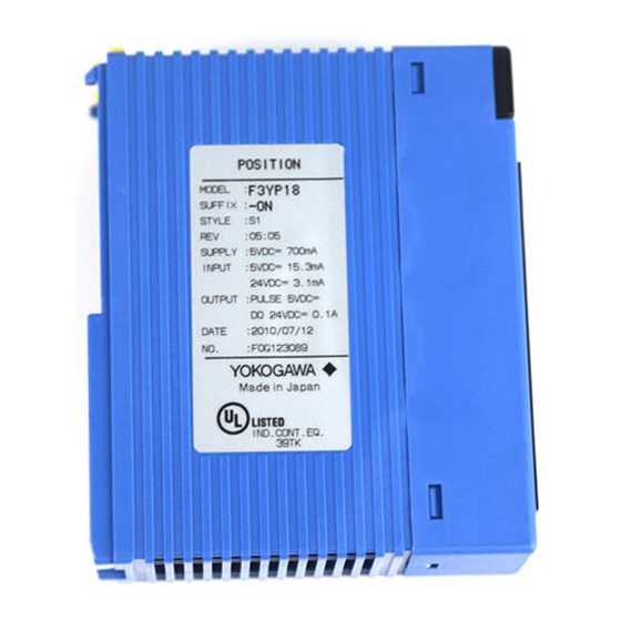
Components and Functions zF3YP14-0N (4-axis module) RDY indicator: Lit when the internal circuitry is functioning normally YP14-0N POSIT ERR indicator: Lit when an error occurs. For details, refer to Section 8.2, "Error Codes." Connector for axes 1 to 4 (48P) Connects to external I/O devices such as servo motors and limit switches zF3YP18-0N (8-axis module) -
Page 18: External Dimensions
External Dimensions Unit: mm 83.2 28.9 F020501.VSD Diagram shown above is for the F3YP14-0N module IM 34M6H55-02E 1st Edition : Apr 1, 2002-00... -
Page 19: Terminal Assignments And Connections
Terminal Assignments and Connections YP14-0N YP18-0N POSIT POSIT F020601.VSD Axis 4 Z-phase input (-) Axis 2 Z-phase input (-) Axis 8 Z-phase input (-) Axis 6 Z-phase input (-) Axis 4 Z-phase input (+) Axis 2 Z-phase input (+) Axis 8 Z-phase input (+) Axis 6 Z-phase input (+) Axis 4 pulse output A (+) Axis 2 pulse output A (+) -
Page 20: Applicable External Interface Connectors
External power 5Vin 5 V DC External power 5Vin (GND) Forward pulse - Forward pulse + Reverse pulse - Reverse pulse + Deviation pulse clear Deviation pulse clear (GND) Z-phase input - z-phase input + Origin input Positive-direction limit input Negative-direction limit input 24 V DC Contact input common... -
Page 21: Attaching And Detaching Modules
Attaching and Detaching Modules T T T T Attaching/Detaching Modules Figure 2.1 shows how to attach the module to the base module. First, hook the anchor slot at the bottom of the module to be attached onto the anchor pin on the bottom of the base module. - Page 22 T T T T Attaching Module in Intense Vibration Environments If the module is used in intense vibration environments, fasten the module with a screw as described in the table below by screwing it into the threaded hole at the top of the module with a Phillips screwdriver.
- Page 23 Blank Page...
-
Page 24: Function Overview
Function Overview This chapter explains the major functions of the positioning modules. For details on how to use each function, see Chapter 7. Table 3.1 summarizes the functions discussed in this chapter. Table 3.1 Major Functions Function Description Positioning operation Performs normal positioning. -
Page 25: Positioning Operation
Positioning Operation To initiate a positioning operation, write the target position, target speed, acceleration time, and deceleration time from the CPU module, set the command code to 0, and change the state of the Execute Command output relay from off to on. When the positioning operation is completed, the End of Positioning input relay turns on. - Page 26 Speed Speed Target speed Target speed Actual speed reached Time Time Acceleration time Deceleration time Acceleration time Deceleration time Actual acceleration/ deceleration time F030104.VSD Figure 3.4 Acceleration/Deceleration Times when Using S-shape Acceleration/Deceleration IM 34M6H55-02E 1st Edition : Apr 1, 2002-00...
-
Page 27: Jog Stepping
Jog Stepping To perform jog stepping, first write the target velocity, acceleration time, deceleration time and other required parameters from the CPU module, and then change the state of the Positive-direction Jog Stepping output relay or Negative-direction Jog Stepping output relay from off to on. To stop job stepping, turn off the corresponding output relay. During jog stepping, any error in the positive-direction or negative-direction limit value will not be detected (no error occurs). -
Page 28: Contact Inputs
Contact Inputs The positioning module has three external contact inputs defined as “Positive-direction limit,” “Negative-direction limit,” and “Origin” for each axis. You can read the state of each contact input using an application program. You can set the polarity of each contact input separately. Z-phase Encoder Input For improved repeatability in origin searches, you can use a Z-phase encoder input. - Page 29 z z z z Details on Origin Search Mode The origin search mode defines the operation when an edge is detected in each contact input using bit combinations. One out of four 2-bit combinations can be selected for each rising/falling edge of an external contact input.
-
Page 30: Automatic Origin Search
Automatic Origin Search There are two ways to perform origin search: normal and automatic. In normal origin search, the origin search behavior is arbitrarily defined by an application program; the automatic origin search operation uses entry parameters to define the origin search behavior. - Page 31 z z z z If the axis is right on the origin switch (with the origin switch input on) at origin search start Search speed 2 Startup speed Z-phasse pulse Positive-direction limit Origin Negative-direction limit F030602.VSD z z z z If the axis is between the origin and the negative limit switch at origin search start Search speed 1...
- Page 32 z z z z If the axis is away from the negative limit switch at origin search start Search speed 1 Search speed 2 Startup speed Z-phase pulse Positive-direction limit Negative-direction limit F030605.vsd z z z z If the axis is right on the negative limit switch at origin search start Search speed 2 Startup speed Z-phase pulse...
-
Page 33: Deviation Pulse Clear Signal Output
3-10 Deviation Pulse Clear Signal Output In an origin search using a servo driver, this outputs a deviation pulse clear signal at the end of the origin search to the servo driver. The deviation pulse clear signal is connected to the input of the servo driver. The length of the deviation pulse clear signal output is defined in a parameter. -
Page 34: Linear-Interpolated Operation
3-11 Linear-Interpolated Operation To perform a linear-interpolated operation, write the target speed, target position, acceleration time, deceleration time and other necessary parameters for each axis from the CPU module, set the command code to “0”, and change the state of the Execute Command output relay from off to on for all axes simultaneously. -
Page 35: Changing Speed During Operation
3-12 Changing Speed during Operation To change the speed of an axis currently moving in a positioning or jog stepping operation, write a new target speed and acceleration/deceleration time, set the command code to 6 (Change Speed command), and change the state of the Execute Command output relay from off to on. -
Page 36: Changing Target Position During Positioning
3-13 3.10 Changing Target Position during Positioning To change the target position during positioning, write a new target position, set the command code to 7 (Change Target Position command), and change the state of the Execute Command output relay from off to on. A new target position issued during positioning may require a reversal of the direction of a moving axis. -
Page 37: Saving Entry Parameters
3-14 3.11 Saving Entry Parameters When all axes are at rest, you can save entry parameters in the flash memory. Entry parameters must be set for all axes with the Set Parameter command before you can save the parameters in the flash memory. You can issue the Save Parameter command for a particular axis. -
Page 38: Parameters
Parameters Parameters Of the parameters given Tables 4.2 and 4.3, those listed with two data position numbers are 2 word data. The smaller data position number contains the low-order word, and the larger data position number contains the high-order word. Data position numbers are three-digit numbers;... - Page 39 Store the remainder in D0013 (the low-order word) and D0014 (the high-order word). Since the divisor is 1000, the maximum value of the remainder is 999 and the high-order word of the remainder (D0014) is always 0. D00011 D00001 1000 Computation result D00014 D00013...
- Page 40 In the case of 123450 [pulse/s] (1) D0011 = 123450/1000 (long-word division) D00014 D00013 D00012 D00011 29491200 (=450×65536) (2) D0021 = 29491200/1000 (long-word division) D00024 D00023 D00022 D00021 29491 From the results, the high-order word of the long-word data ([(1/65536) pulses/ms]) to be set in the positioning module is 123, and the low-order word is 29491.
-
Page 41: Parameters
4.1.1 Entry Parameters At power up or system reset, the content of the flash memory is automatically reloaded to the entry parameters. To change the settings of the entry parameters, write new parameter settings from the CPU module, and execute the Set Parameter command. Table 4.2 Entry parameters Data Position Parameter... -
Page 42: Command Parameters
4.1.2 Command Parameters These are parameters to be set when executing a command. It is necessary to write all the required parameters when executing a command. Table 4.3 Command Parameters Data Position Parameter Range of values Number Command Code 0 to 9, and 99 Target Position Mode 0: Absolute position, 1: Relative position *43/*44... -
Page 43: Required Parameters For Each Command
Required Parameters for Each Command You must write all the required parameters before executing a command for the positioning module from the CPU module. Table 4.4 shows the required parameters for each command. The Set Parameter command and the Save Parameter command that respectively updates and saves all the entry parameters are not shown in the table. -
Page 44: Description Of Parameters
Description of Parameters 4.3.1 Entry parameters At power up, the content of the flash memory is automatically reloaded to the entry parameters. Modify the values of the entry parameters as necessary using the Set Parameter command in an application program. If a parameter value is invalid, the Error Notification input relay is set, and an entry parameter setting error results. - Page 45 Parameter Type (Data Position Description Data Range Remarks Number) Automatic Origin Specifies whether the 0: Origin input is used. For details, refer to Section 3.5, “Origin Search Mode origin input is used for 1: Origin input is not used. Search.” (*11) automatic origin search.
-
Page 46: Command Parameters
4.3.2 Command Parameters Table 4.6 Command Parameters Parameter Type Description Data Range Remarks (Data Position Number) Command Code Sets the command type for 0: Start Positioning command (*41) command execution using the 1: Decelerate-and-Stop command Execute Command relay. 2: Normal Origin Search command 3: Set Parameter command 4: Set Current Position command... - Page 47 4-10 (Continued to the next page) Parameter Type (Data Position Description Data Range Remarks Number) Origin Search Mode Defines, using bit patterns, the 0 to 4095 For details, see Section 3.5, (*52) behavior of the motor when “Origin-search Operation.” the edges of each contact input is detected during an origin search.
-
Page 48: Example For Setting Entry Parameters
4-11 Example for Setting Entry Parameters The following example shows a minimal set of entry parameters, which must be defined for controlling a motor using the positioning module. The underlined values are to be entered. z z z z The motor used Rated rotating speed: 3000 rpm Encoder pulse count: 8000 pulses per rotation CAUTION... - Page 49 4-12 – Speed limit (*09/*10) The maximum pulse output speed allowed by the motor is: 3000 [rpm] ÷ 60 [s/min] × 8000 [pulse/rot] = 400000 [pulse/s]. The maximum pulse output speed allowed by the ball screw is: 200 [mm/s] ÷ 5 [mm/rot] × 8000 [pulse/rot] = 320000 [pulse/s] Thus, the maximum pulse output speed for this system is 320000 [pulse/s].
-
Page 50: Status
Status Status refers to data which the CPU module reads from the positioning module. You can check the state of the positioning module using the status and input relays. CAUTION When the CPU module reads 2-word data from the positioning module, concurrency of the high-order word and low-order word of 2-word data is not assured due to conflicts between the timing of reading from the CPU module and the data update period of the positioning module. -
Page 51: List Of Status
List of Status In Table 5.1, status listed with 2 data position numbers are 2-word data. The smaller number data position number contains the low-order word, and the larger data position number contains the high-order word. The data position number consists of three digits; the leading ‘ is the value of (axis *’... -
Page 52: Description Of Statuses
Description of Statuses Table 5.2 Status Data Position Status Description Number Reads the operation target position during a positioning operation. *81/*82 Target Position The operation target position is determined from the Target Position Mode and Status [pulses] Target Position, set at the beginning of the positioning. The Operation Target Position always contains absolute position data, regardless of whether the Target Position Mode is absolute or relative. - Page 53 Blank Page...
-
Page 54: Input/Output Relays
FA-M3 CPU module. For details on each input/output relay, refer to Chapter 7, “Accessing Modules.” CAUTION For the F3YP14-0N, NEVER set the output relays for axes 5 to 8. Input relays for axes 5 to 8 have no meaning. Output Relays Table 6.1 lists the output relays available in this positioning module. -
Page 55: Input Relays
Input Relays Table 6.2 lists the input relays available in this positioning module. An interrupt signal can be sent to the CPU module by changing the state of an input relay from off to on. Table 6.2 Input Relays Input relay Input relay Operation when ON Operation when ON... -
Page 56: Accessing Modules
4 (slot #004) of the main unit; it also assumes that when only one axis is used, it is axis 1. CAUTION On the F3YP14-0N module, NEVER set the output relays for axes 5 to 8; moreover, Input relays for axes 5 to 8 have no meaning. Accessing from Sequence CPU The following instructions can be used for accessing the module from a sequence CPU using a ladder sequence program. -
Page 57: Reading Module Statuses
7.1.1 Reading Module Statuses This section explains how to read the status of the positioning module. z z z z Note: The status of the positioning module can be read at any time. Take care when reading long-word data. See Chapter 5, “Status.” z z z z Sample Program: In the example below, all of the statuses are read at the same time using a single READ... -
Page 58: Set Parameter
7.1.2 Set Parameter The Set Parameter command sets the entry parameters. z z z z Conditions for Command Execution: - The axis is in the End-of-Positioning status. - No other command is being executed. z z z z Note: - If any of the conditions is not satisfied, the command is ignored (the Command Execution ACK relay is not set). - Page 59 z z z z Sample Program: In this example, parameters are preset in the data registers. All entry parameters are written at one go with the WRITE instruction. Major devices used D00001 Maximum speed selection D00002 Pulse output mode D00003 Direction of rotation D00004 Contact input polarity...
- Page 60 Figure 7.2 Set Parameter Program IM 34M6H55-02E 1st Edition : Apr 1, 2002-00...
- Page 61 I00101 I00102 I00103 I00104 Y00433 X00401 F070103.VSD Figure 7.3 Time Chart for the Set Parameter Program IM 34M6H55-02E 1st Edition : Apr 1, 2002-00...
-
Page 62: Reset Error
7.1.3 Reset Error The Reset Error command resets the error status of the positioning module. z z z z Conditions for Command Execution: - The axis is in error (other than an entry parameter error). - No other command is being executed. z z z z Note: - The positioning module ignores all commands other than the Reset Error command... - Page 63 Figure 7.4 Reset Error Program I00111 I00112 I00113 I00114 Y00433 X00401 X00417 F070105.VSD Figure 7.5 Time Chart for the Reset Error Program IM 34M6H55-02E 1st Edition : Apr 1, 2002-00...
-
Page 64: Jog Stepping
7.1.4 Jog Stepping When the Positive- (Negative-) direction Jog Stepping output relay is on, the axis moves in the positive (negative) direction. z z z z Conditions for Command Execution: - The axis is not in an error state. - The axis is in the End-of-Positioning status. - No other command is being executed. - Page 65 7-10 Figure 7.6 Jog Stepping Program IM 34M6H55-02E 1st Edition : Apr 1, 2002-00...
- Page 66 7-11 Motor speed I00121 I00122 I00123 I00124 Y00449 X00425 F070107.VSD Figure 7.7 Time Chart for the Jog Stepping Program IM 34M6H55-02E 1st Edition : Apr 1, 2002-00...
-
Page 67: Origin Search
7-12 7.1.5 Origin Search There are two ways to perform origin search operation: normal and automatic. In the normal origin search operation, the origin search behavior is arbitrarily defined by an application program. The automatic origin search operation uses entry parameters to define the origin search behavior. - Page 68 7-13 - After shifting to a Z-phase search, even if the external contact input that activates the Stop Immediately or Decelerate and Stop operation is detected, the Z-search operation will continue. (This behavior is different from the origin search in the F3NC11-0N and F3NC12-0N modules) - During the origin search, no error occurs even if the axis exceeds the range defined by the positive and negative direction limit values.
- Page 69 7-14 Figure 7.9 Origin Search Program IM 34M6H55-02E 1st Edition : Apr 1, 2002-00...
- Page 70 7-15 Stop immediately Motor speed at origin I00131 I00132 I00133 I00134 Y00433 X00401 X00425 F070110.VSD Figure 7.10 Time Chart for the Origin Search Program IM 34M6H55-02E 1st Edition : Apr 1, 2002-00...
-
Page 71: Automatic Origin Search
7-16 7.1.6 Automatic Origin Search There are two ways to perform origin search: normal and automatic. In normal origin search, the search behavior is arbitrarily defined by an application program. The automatic origin search operation uses entry parameters to define the origin search behavior. - Page 72 7-17 z z z z Sample Program: This program starts the automatic origin search operation using the Request to Start Automatic Origin Search and stops the operation using Z-phase detected. The program stops the operation if it detects an error during operation. Major devices used D00489 Alarm code storage device...
- Page 73 7-18 Stop immediately Motor speed at origin I00136 I00137 I00138 I00139 Y00433 X00401 X00425 F070112.VSD Figure 7.12 Time Chart for the Automatic Origin Search Program IM 34M6H55-02E 1st Edition : Apr 1, 2002-00...
-
Page 74: Set Current Position
7-19 7.1.7 Set Current Position The Set Current Position command changes the current position of an axis in the End of Positioning status. z z z z Conditions for Command Execution: - The axis is not in an error state. - The axis is in the End-of-Positioning status. - Page 75 7-20 Figure 7.13 Set Current Position Program I00141 I00142 I00143 I00144 Y00433 X00401 F070114.VSD Figure 7.14 Time Chart for the Set Current Position Program IM 34M6H55-02E 1st Edition : Apr 1, 2002-00...
-
Page 76: Positioning Operation
7-21 7.1.8 Positioning Operation This command executes a positioning operation towards a preset target position. z z z z Conditions for Command Execution: - The axis is not in an error state. - The axis is in the End-of-Positioning status. - No other command is being executed. - Page 77 7-22 Figure 7.15 Positioning Operation Program IM 34M6H55-02E 1st Edition : Apr 1, 2002-00...
- Page 78 7-23 Motor speed I00151 I00152 I00153 I00154 Y00433 X00401 X00425 F070116.VSD Figure 7.16 Time Chart for the Positioning Operation Program IM 34M6H55-02E 1st Edition : Apr 1, 2002-00...
-
Page 79: Request To Decelerate And Stop
7-24 7.1.9 Request to Decelerate and Stop This Request to Decelerate and Stop command decelerates and stops a moving motor during a positioning operation, origin search, etc. The rate of deceleration is determined from the preset values at startup. z z z z Conditions for Command Execution: - The axis is not in an error state. - Page 80 7-25 Figure 7.17 Request to Decelerate and Stop Program Motor Speed I00161 I00162 I00163 I00164 Y00433 X00401 X00425 F070118.VSD Figure 7.18 Time Chart for the Request to Decelerate and Stop Program IM 34M6H55-02E 1st Edition : Apr 1, 2002-00...
-
Page 81: Request To Stop Immediately
7-26 7.1.10 Request to Stop Immediately The Request to Stop Immediately command stops a moving motor immediately without any deceleration during a positioning operation, origin search, etc. z z z z Conditions for the Command: - The axis is not in an error state. z z z z Note: - If any of the conditions is not satisfied, the command is ignored and the Stop Immediately ACK relay is not set. - Page 82 7-27 Figure 7.19 Request to Stop Immediately Program Motor Speed I00171 I00172 I00173 I00174 Y00433 X00401 X00425 F070120.VSD Figure 7.20 Time Chart for the Request to Stop Immediately Program IM 34M6H55-02E 1st Edition : Apr 1, 2002-00...
-
Page 83: Changing Speed During Operation
7-28 7.1.11 Changing Speed during Operation When the Change Speed command is issued during a positioning operation, the axis immediately starts to accelerate (or decelerate) to the new speed at a rate determined by the new speed and the acceleration (or deceleration) time. When the axis subsequently decelerates and stops from the new target speed to complete the positioning operation, or when the Decelerate-and-Stop command is issued, the deceleration rate is determined by the new speed and the deceleration time. - Page 84 7-29 z z z z Sample Program This program changes speed during operation. All required parameters are preset in the data registers. Major devices used D00941 Command code D00942 to D00945 Area for non-required parameters D00946/D00947 Target speed D00948 Acceleration time D00949 Deceleration time D00989...
- Page 85 7-30 I00181 I00182 I00183 I00184 Y00433 X00401 F070122.VSD Figure 7.22 Time Program for the Request to Change Target Speed Program IM 34M6H55-02E 1st Edition : Apr 1, 2002-00...
-
Page 86: Changing Target Position During Positioning
7-31 7.1.12 Changing Target Position during Positioning When the Change Target Position command is issued during a positioning operation, the module updates the target position and performs positioning to reach the new target position. Changing the target speed, acceleration or deceleration is not allowed during the execution of the change target position command. - Page 87 7-32 z z z z Sample Program: This program changes the target position during a positioning operation. All required parameters are preset in the data registers. Major devices used D01041 Command code D01042 Target position mode D01043/D01044 Target position D01089 Alarm code storage device Y00433 Execute Command output relay...
- Page 88 7-33 I00191 I00192 I00193 I00194 Y00433 X00401 F070124.VSD Figure 7.24 Time Chart for the Request to Change Target Position Program IM 34M6H55-02E 1st Edition : Apr 1, 2002-00...
-
Page 89: Saving Entry Parameters
7-34 7.1.13 Saving Entry Parameters When all axes are at rest, you can save all entry parameters to the flash memory. You can issue the Save Parameter command for any axis but the entry parameters of all axes are saved to the flash memory, regardless. z z z z Conditions for Command Execution: - No axis is in an error state. - Page 90 7-35 Figure 7.25 Request to Save Entry Parameters Program I00201 I00202 I00203 I00204 Y00433 X00401 F070126.VSD Figure 7.26 Time Chart for the Request to Save Entry Parameters Program IM 34M6H55-02E 1st Edition : Apr 1, 2002-00...
-
Page 91: Accessing From A Basic Cpu
7-36 Accessing from a BASIC CPU You can use the following the commands to access the module from a BASIC CPU. For details of each command, see “Basic CPU Modules and YM-BASIC/FA Programming Language” (IM 34M6Q22-01E). Function Statement Format Explanation Module use ASSIGN YP18 = SL Declares use of a module or CPU module. -
Page 92: Reading Module Statuses
7-37 7.2.1 Reading Module Statuses This section explains how to read the status of the positioning module. z z z z Note: - The status of the positioning module can be read at any time. Use the ENTER instruction to read the status. - 2-word data status, such as the current position or current speed status, must be read as two separate integer variables. -
Page 93: Set Parameter
7-38 7.2.2 Set Parameter The Set Parameter command sets the entry parameters. z z z z Conditions for Command Execution: - The axis is in the End-of-Positioning status. - No other command is being executed. z z z z Note: - If any of the conditions is not satisfied, the command is ignored and the Command Execution ACK relay is not set. -
Page 94: Reset Error
7-39 7.2.3 Reset Error The Reset Error command resets the error status of the positioning module. z z z z Conditions for Command Execution: - The axis is in error (other than an entry parameter error) - No other command is being executed. z z z z Note: - The positioning module ignores all commands other than the Reset Error command... -
Page 95: Jog Stepping
7-40 7.2.4 Jog Stepping When the Positive- (Negative-) direction Jog Stepping output relay is on, the motor moves in the positive (negative) direction. z z z z Conditions for Command Execution: - The axis is not in an error state. - The axis is in the End-of-Positioning status. -
Page 96: Origin Search
7-41 7.2.5 Origin Search There are two ways to perform origin search: normal and automatic. In normal origin search, the origin search behavior is arbitrarily defined by an application program; the automatic origin search operation uses entry parameters to define the origin search behavior. - Page 97 7-42 z z z z Conditions for Command Execution: - The axis is not in an error state. - The axis is in the End-of-Positioning status. - No other command is being executed. z z z z Note: - If any of the conditions is not satisfied, the command is ignored and the Command Execution ACK relay is not set.
- Page 98 7-43 z z z z Sample Program: This program starts the origin search using the Request to Search Origin input and stops the search using a designated external contact input. If any error is detected during the search, the search mode is automatically reset. All required parameters are preset in integer variables (I41, and I46 to I58).
-
Page 99: Automatic Origin Search
7-44 7.2.6 Automatic Origin Search There are two ways to perform origin search: normal and automatic. In normal origin search, the origin search behavior is arbitrarily defined by an application program; the automatic origin search operation uses entry parameters to define the origin search behavior. - Page 100 7-45 z z z z Sample Program: This program starts the automatic origin search operation using the Request to Start Automatic Origin Search, performs Z-phase detection and stops the operation. The program also stops the operation if it detects an error during the operation. All required parameters are preset in an integer variable (I41).
-
Page 101: Set Current Position
7-46 7.2.7 Set Current Position The Set Current Position command changes the current position of an axis in the End of Positioning status. z z z z Conditions for Command Execution: - The axis is not in an error state. - The axis is in the End-of-Positioning status. -
Page 102: Positioning Operation
7-47 7.2.8 Positioning Operation This executes a positioning operation towards a preset target position. z z z z Conditions for Command Execution: - The axis is not in an error state. - The axis is in the End-of-Positioning status. - No other command is being executed. z z z z Note: If any of the conditions is not satisfied, the command is ignored and the Command... - Page 103 7-48 z z z z Sample Program This is a sample program for a positioning operation. All required parameters are preset in integer variables (I41 to I51). 100 OUTPUT SL,42 NOFORMAT;I42 110 OUTPUT SL,43 NOFORMAT;I43 190 OUTPUT SL,51 NOFORMAT;I51 200 OUTPUT SL,41 NOFORMAT;I41 210 CONTROL SL,101;$0001,$0001 220 LOOP1@ 230 STATUS SL,101;P...
-
Page 104: Request To Decelerate And Stop
7-49 7.2.9 Request to Decelerate and Stop The Request to Decelerate and Stop command decelerates and stops a moving motor during a positioning operation, origin search, etc. The rate of deceleration is determined from the preset values at startup. z z z z Conditions for Command Execution: - The axis is not in an error state. -
Page 105: Request To Stop Immediately
7-50 7.2.10 Request to Stop Immediately The Request to Stop Immediately command stops an operating motor immediately without deceleration during a positioning operation, origin search, etc. z z z z Conditions for Command Execution: - The axis is not in an error state. z z z z Note: - If any of the conditions is not satisfied, the command is ignored and the Stop... -
Page 106: Changing Speed During Operation
7-51 7.2.11 Changing Speed during Operation When the Change Speed command is issued during a positioning operation, the axis immediately starts to accelerate (or decelerate) to the new speed at a rate determined by the new speed and the new acceleration (or deceleration) time. When the axis subsequently decelerates from the new speed and stops to complete the positioning operation, or when a Decelerate-and-Stop command is issued, the deceleration rate is determined by the new speed and the deceleration time. - Page 107 7-52 z z z z Sample Program: This program changes the speed during operation. All required parameters are preset in integer variables (I41, and I46 to I49). 100 OUTPUT SL,46 NOFORMAT;I46 110 OUTPUT SL,47 NOFORMAT;I47 120 OUTPUT SL,48 NOFORMAT;I48 130 OUTPUT SL,49 NOFORMAT;I49 140 OUTPUT SL,41 NOFORMAT;I41 150 CONTROL SL,101;$0001,$0001 160 LOOP1@...
-
Page 108: Changing Target Position During Positioning
7-53 7.2.12 Changing Target Position during Positioning When the Change Target Position command is issued during a positioning operation, the module updates the target position and performs positioning to reach the new target position. Changing the target speed, acceleration or deceleration is not allowed during the execution of the change target position command. - Page 109 7-54 z z z z Sample Program: This program changes the target position during a positioning operation. All required parameters are preset in integer variables (I41, I46 to I49). 100 OUTPUT SL,42 NOFORMAT;I42 110 OUTPUT SL,43 NOFORMAT;I43 120 OUTPUT SL,44 NOFORMAT;I44 130 OUTPUT SL,41 NOFORMAT;I41 140 CONTROL SL,101;$0001,$0001 150 LOOP1@...
-
Page 110: Saving Entry Parameters
7-55 7.2.13 Saving Entry Parameters When all axes are at rest, you can save all entry parameters to the flash memory. You can issue the Save Parameter command for any axis but the entry parameters of all axes are saved to the flash memory, regardless. z z z z Conditions for Command Execution: - No axis is in an error state. - Page 111 Blank Page...
-
Page 112: Errors And Troubleshooting
Errors and Troubleshooting This section describes troubleshooting on the positioning module. However, it assumes that power is supplied to the FA-M3 and the module is installed correctly. Troubleshooting Flow Error RDY LED Replace the module. When jog stepping, leave the values of all entry parameters at their factory defaults, set the high- Forward (reverse) order word for the target speed command parameter... -
Page 113: Error Codes
Error Codes When an error occurs in any axis in the positioning module, the Error LED at the front of the module lights up to indicate that an error has occurred. The Error Notification input relay related to the axis is set. The error code status is also set. When the Error LED lights up, axes other than the one in error can still operate. - Page 114 Error Trouble- Description of Error Cause of Error Code shooting 2001 Maximum speed selection Maximum speed selection setting is beyond the setting range Set a value setting error (0 and 1). within the setting range. 2002 Pulse output mode setting error Pulse output mode setting is beyond the setting range (0 and 1).
-
Page 115: Alarm Codes
Alarm Codes When the positioning module issues an alarm for any axis, it writes an alarm code in the Alarm Status for the axis. An alarm is issued when an executed command does not meet the conditions for proper execution. Resetting the Execute Command relay or other output relay related to the invalid command clears the Alarm Status. -
Page 116: External Interface Signals
The positioning modules output positioning command pulses as RS422A compliant differential signals. An external power supply (5 V DC ±5%, 350 mA for the F3YP14-0N; or 5 V DC ±5%, 700 mA for the F3YP18-0N, is required for positioning command pulse output. -
Page 117: External Contact Input
External Contact Input These are 24 V DC inputs with a common terminal. The polarity of the common may be either positive or negative. It is insulated from the internal circuitry by a photocoupler. Table 9.3 Signal Specifications Item Specifications Insulation method Photocoupler-isolated Input impedance... -
Page 118: Encoder Z-Phase Input
Encoder Z-phase Input This is the encoder Z-phase input. It is used only during an origin search. You may also connect a RS422A compliant differential signal. Table 9.4 Signal Specifications Item Specifications Insulation method Photocoupler-isolated Input impedance 240 Ω Rated input voltage 5 V DC (operating voltage range) (4.25 to 5.5 V DC) -
Page 119: Deviation Pulse Clear Signal Output
Deviation Pulse Clear Signal Output When using a servomotor/driver, this signal output is used to clear the deviation pulse count of the servo driver when the origin search ends. It is insulated from the internal circuitry by a photocoupler. Table 9.5 Signal Specifications Item Specifications Insulation method... -
Page 120: Examples Of Connections To Drivers
10-1 10. Examples of Connections to Drivers This chapter presents examples of connections of the module to motor or drivers. Note that the figures indicate canonical connections. Other signals may also have to be connected depending on your application. CAUTION - Make sure that the polarity of the ‘+’... -
Page 121: Example Of Connection To Oriental Motor Driver
10-2 10.1 Example of Connection to Oriental Motor Driver Positioning module F3YP14-0N/F3YP18-0N Oriental Motor Driver Forward pulse - CW pulse + Forward pulse + CW pulse - Reverse pulse - CCW pulse + Reverse pulse + CCW pulse - Deviation pulse clear... -
Page 122: Example Of Connection To Yasukawa Electric Sii-Series Driver
10-3 10.2 Example of Connection to YASUKAWA Electric ΣII-Series Driver Positioning module F3YP14-0N/F3YP18-0N YASUKAWA Electric Servo Pack SGDM CW pulse Forward pulse - CW pulse* Forward pulse + CCW pulse Reverse pulse - CCW pulse * Reverse pulse + CLR *... -
Page 123: Example Of Connection To Sanyo Denki Pz Series Driver
10-4 10.3 Example of Connection to Sanyo Denki PZ Series Driver Positioning module F3YP14-0N/F3YP18-0N Sanyo Denki PZ series driver Forward pulse - Forward pulse - Forward pulse + Forward pulse + Reverse pulse - Reverse pulse - Reverse pulse +... - Page 124 Index FA-M3 Positioning Modules (with Multi-channel Pulse Output) Model: F3YP14-0N, F3YP18-0N IM 34M6H55-02E Forward pulse ........ 2-1,2-4,4-7,9-1 Index Input relay .......... 6-2,7-1,7-36 Acceleration time ....... 3-2,3-11,4-9 Alarm..........5-2,5-3,7-2,8-4 Jog stepping ......3-1,3-4,6-1,7-9,7-40 Automatic origin search ..3-7,4-8,4-9,7-16,7-44 Limit input ........2-4,3-5,5-3,8-2 Change speed ....3-12,4-6,4-9,7-28,7-51 Linear-interpolated operation .....2-1,3-1,3-11...
- Page 125 Index Startup speed........3-2,4-8,4-9 Startup time..........1-1,2-1 Status ........5-1,7-1,7-2,7-36,7-37 Stop immediately ACK ..... 6-2,7-26,7-50 Stop immediately .......4-6,6-1,7-26,7-50 Target position mode ........4-9 Target position status......5-2,5-3,7-2 Target position ........... 3-2,4-9 Target speed ........3-2,3-11,4-9 Trapezoidal acceleration/deceleration. 3-2,3-4,4-9 Z-phase edge selection ......4-8,4-10 Z-phase input.........2-4,3-1,3-5,5-3 Z-phase search count......
-
Page 126: Revision Information
Revised Item April, 2002 New Publication Written by Product Marketing Department, IT Controller Center Yokogawa Electric Corporation Published by Yokogawa Electric Corporation 2-9-32 Nakacho, Musashino-shi, Tokyo 180-8750, JAPAN Printed by Yokogawa Graphic Arts Co., Ltd. IM 34M6H55-02E 1st Edition : Apr.1.2002-00... - Page 127 Blank Page...
Need help?
Do you have a question about the F3YP14-0N and is the answer not in the manual?
Questions and answers