Advertisement
Quick Links
SRBE-...-EX
Limit switch box
Operating instruction
8169567
2022-11d
[8169569]
Translation of the original instructions
© 2022 all rights reserved to Festo SE & Co. KG
1
Identification EX
Identification
Ex db IIC T6 Gb
Ex tb IIIC T(*) Db
TM
II 2G
Ex db IIC T6 Gb
II 2D
Ex tb IIIC T(*)°C Db
Ex db IIC T6 Gb
Ex tb IIIC T(*) Db
Ex db IIC T6 Gb
Ex tb IIIC T(*) Db
Tab. 1: Identification EX
2
Applicable documents
NOTICE
Technical data for the product can have different values in other documents. For
operation in an explosive atmosphere, the technical data in this document always
have priority.
All available documents for the product è www.festo.com/sp.
3
Safety
3.1
Safety instructions
– The device can be used under the stated operating conditions in zone 1, explo-
sive gas atmospheres, and in zone 21, explosive dust atmospheres.
– Standards applicable to Inmetro: ABNT NBR IEC 60079-0, ABNT NBR IEC
60079-1, ABNT NBR IEC 60079-31.
3.2
Intended use
The intended use of the product is to record and display the end positions and
intermediate positions of pneumatic drives.
3.3
Training of qualified personnel
Work on the product may only be carried out by qualified personnel who can
evaluate the work and detect dangers. The qualified personnel have skills and
experience in dealing with electrical (open-loop) control technology.
3.4
Identification X: special conditions
– Ambient temperature -20 °C £ Ta £ +60 °C
– Prepare the Ex cable fittings and blanking plugs in the Ex degree of protection
according to the identification in this certificate with at least IP66/IP67.
– Contact the manufacturer for information on the dimensions of the pressure-
resistant connections.
– Install the product in such a way that there is no danger of spreading brush
discharges when used in explosive dust atmospheres.
– The minimum property class of the captive screws used is A2-70 or A4-70.
4
Additional information
– Contact the regional Festo contact if you have technical problems
è www.festo.com.
– Accessories and spare parts è www.festo.com/catalogue.
Festo SE & Co. KG
Ruiter Straße 82
73734 Esslingen
Germany
+49 711 347-0
www.festo.com
8169567
Certificates
IECEx FTZU 15.0014X
FTZU 15 ATEX 0095X
DNV 16.0067X
GYJ16.1497X
5
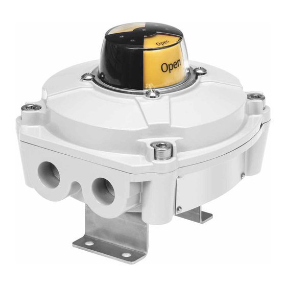
Product overview
Fig.1
Default settings on delivery:
– Position indicator "closed"
– Switching point for "open" 90° anti-clockwise
6
Function
The limit switch box is used for the detection and electrical and optical feedback
of the end positions of a drive. The limit switch box is suitable for operation
with semi-rotary drives with a mechanical interface in accordance with VDI/VDE
Guideline 3845.
7
Installation
WARNING
Carry out the commissioning, service and inspection outside of the explosive
atmosphere. Disconnect the power supply before this work and secure against
reconnection.
1. Close the process valve.
2. Place the limit switch box with the mounting adapter on the drive and align it.
– Avoid axial load of the drive shaft.
3. Fasten the mounting adapter to the drive.
– Lock the retaining screws. Tightening torque: 6 Nm ± 10%
Mounting adapter
Observe the tightening torque when replacing the limit switch attachment.
– Tightening torque between mounting adapter and limit switch box: 10 Nm
± 10%
8
Electrical connection
WARNING
Before switching on the electrical circuit in potentially explosive atmospheres:
• Mount the cover securely on the housing.
• Connect with potential equalisation.
WARNING
Use cable connectors of type of (ignition) protection Ex-d and a degree of protec-
tion of at least IP67. Seal unused cable entries with blanking plugs.
NOTICE
Thread of the cable guide depends on the product variant: M20x1.5 or 1/2 NPT
Cable fittings must be appropriate for the corresponding thread type. Cable con-
nector threads must not protrude into the interior of the housing.
NOTICE
The supplied plastic blanking plugs are intended exclusively for protection against
contamination during transport and handling. During operation, these should be
replaced by cable connectors and/or blanking plugs approved for use in explosion
protection areas.
1. Loosen the housing screws [3] on the housing cover [2].
2. Screw the cable fitting into the cable entry [8]. Insert the electrical connecting
cable through the cable fitting to the terminal strip [6].
3. Wire the connections. Maximum tightening torque of the screws: 0.4 Nm è 9
Wiring diagram
4. Connect the earth terminal [7] with low impedance (short cable with large
cross section) to the earth terminal.
5. Place the housing cover in position and tighten the housing screws.
– Make sure that the seal is positioned correctly.
1
Position indicator
1
2
Housing cover
2
3
Housing screws
4
Shaft with cam
3
5
Proximity switch
6
Terminal strip
4
5
Protective earthing (PE) on the
7
inside and outside of the housing
6
wall
8
Cable entry M20x1.5 or 1/2 NPT
7
8
Mounting adapter with M5x8
9
retaining screws
9
Advertisement

Related Manuals for Festo SRBE Series


Summary of Contents for Festo SRBE Series
- Page 1 Translation of the original instructions Function © 2022 all rights reserved to Festo SE & Co. KG The limit switch box is used for the detection and electrical and optical feedback of the end positions of a drive. The limit switch box is suitable for operation...
- Page 2 Wiring diagram Fault clearance SRBE-Cxx-YR90-MW-22A-1W-…/SRBE-Cxx-YR90-R-2A-1W-… Fault description Cause Remedy Incorrect or unexpected signal Wire break Replace cable Position of the switching points incorrect Set switching points Proximity switch defective Replace limit switch box Tab. 2 Technical data SRBE-... Fig. 2: Two SPDT micro-switches, mechanical or magnetic Angular detection setting range [°] 0 … 90...
Need help?
Do you have a question about the SRBE Series and is the answer not in the manual?
Questions and answers