Table of Contents
Advertisement
Quick Links
SRBE-...-EX
Limit Switch Box
Operating instructions
8141485
2020-07c
[8141487]
Translation of the original instructions
© 2020 all rights reserved to Festo SE & Co. KG
1
Identification EX
Identification mark
International
Ex db IIC T6 Gb
Ex tb IIIC T(*) Db
Europe
II 2G Ex db IIC T6 Gb
II 2D Ex tb IIIC T(*) Db
China
Ex d IIC T6 Gb
Ex tD A21 IP67 T*
Tab. 1
2
Applicable documents
NOTICE!
Technical Data for the product can have different values in other documents. For
operation in an explosive atmosphere, the technical data in this document always
have priority.
All available documents for the product è www.festo.com/sp.
3
Safety
3.1
Safety instructions
–
The device can be used under the stated operating conditions in zone 1,
explosive gas atmospheres, and in zone 21, explosive dust atmospheres.
–
Observe the product labelling.
3.2
Intended use
The intended use of the product is to record and display the end positions and
intermediate positions of pneumatic drives.
3.3
Identification X: special conditions
–
Ambient temperature: –20 °C £ T
–
Use only cable fittings or sealing plugs that are approved for the applicable
type of (ignition) protection and IP67.
–
Only clean the device with a damp cloth.
–
For further information on the flameproof gaps, contact the manufacturer.
Festo SE & Co. KG
Ruiter Straße 82
73734 Esslingen
Germany
+49 711 347-0
www.festo.com
8141485
Certificate
IECEx FTZU 15.0014X
FTZU 15 ATEX 0095X
GYJ16.1497X
£ +60 °C
a
4
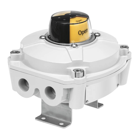
Product overview
1 Position indicator
2 Housing cover
3 Housing screws
4 Shaft with cam
5 Proximity switches
Fig. 1
Default settings on delivery:
–
Position indicator "closed"
–
Switching point for "open" 90° anti-clockwise
5
Additional information
–
Accessories è www.festo.com/catalogue.
–
Service è www.festo.com.
Contact the regional Festo contact if you have technical questions.
6
Function
The limit switch box is used for the detection and electrical and optical feedback
of the end positions of a drive. The limit switch box is suitable for operation with
semi-rotary drives with a mechanical interface in accordance with VDI/VDE
Guideline 3845.
7
Installation
WARNING!
Carry out the commissioning, service and inspection outside of the explosive
atmosphere. Disconnect the power supply before this work and secure against
reconnection.
NOTICE!
Installation and commissioning may only be performed in accordance with the
operating instructions and by qualified personnel.
1. Close process valve.
2. Place the limit switch box with mounting adapter on the drive and align it.
–
Avoid axial load of the drive shaft.
3. Fasten the mounting adapter to the drive.
–
Lock the retaining screws. Tightening torque: 6 Nm ± 10%
Mounting adapter
When replacing the limit switch attachment, observe the tightening torque.
–
Tightening torque between mounting adapter and limit switch box:
10 Nm ± 10%
8
Electrical connection
WARNING!
Before switching on the electrical circuit in potentially explosive atmospheres:
•
Mount the cover securely on the housing.
•
Connect with potential equalisation.
NOTICE!
Thread of the cable guide depends on the product variant: M20x1.5 or 1/2 NPT
Cable fittings must be appropriate for the corresponding thread type. Cable con-
nector threads must not protrude into the interior of the housing.
6 Terminal strip
7 Earth connection (PE) on the inside
and outside of the housing wall
8 Cable inlet M20x1.5 or NPT ½
9 Mounting adapter with retaining
screws M5x10
Advertisement
Table of Contents

Related Manuals for Festo SRBE EX Series


Summary of Contents for Festo SRBE EX Series
- Page 1 Operating instructions 8141485 2020-07c [8141487] 8141485 Translation of the original instructions © 2020 all rights reserved to Festo SE & Co. KG Identification EX 1 Position indicator 6 Terminal strip Identification mark Certificate 2 Housing cover 7 Earth connection (PE) on the inside...
- Page 2 NOTICE! The supplied plastic blanking plugs are intended exclusively for protection against contamination during transport and handling. During operation, these should be replaced by cable connectors and/or blanking plugs approved for use in explosion protection areas. WARNING! Use cable connectors of type of (ignition) protection Ex-d and a degree of protec- Fig.
- Page 3 SRBE-... SRBE-Cxx-YR90-MW-22A-1W-… 6 (30 V); 0.6 (125 V); 0.3 (250 V) SRBE-Cxx-YR90-MW-22A-2W-… SRBE-Cxx-YR90-N-20N-ZC-… [mA] SRBE-Cxx-YR90-N-1-P-… [mA] SRBE-Cxx-YR90-N-1-N-… SRBE-Cxx-YR90-N-1-ZU-… Voltage drop SRBE-Cxx-YR90-N-1-P-… £ 3 SRBE-Cxx-YR90-N-1-N-… SRBE-Cxx-YR90-N-1-ZU-… £ 5 Residual current SRBE-Cxx-YR90-N-1-P-… [mA] £ 15 SRBE-Cxx-YR90-N-1-N-… No-load supply current SRBE-Cxx-YR90-N-1-P-… [mA] 0 … 0.5 SRBE-Cxx-YR90-N-1-N-… SRBE-Cxx-YR90-N-1-ZU-… [mA] 0 … 1 Reverse polarity protection SRBE-Cxx-YR90-N-1-P-…...
Need help?
Do you have a question about the SRBE EX Series and is the answer not in the manual?
Questions and answers