
Related Manuals for Linear m&s VMC1


Summary of Contents for Linear m&s VMC1
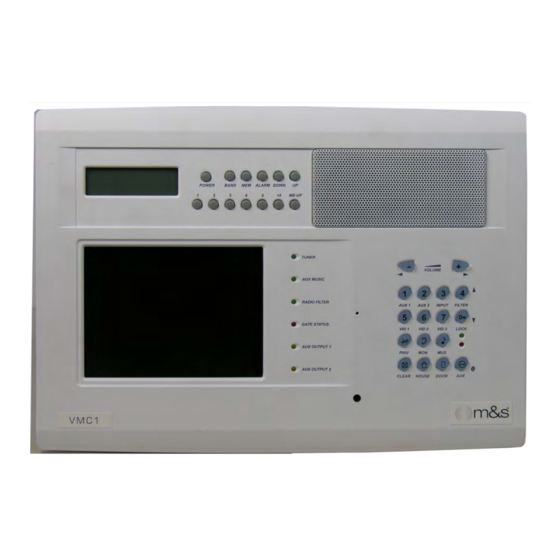
- Page 1 VMC1 Video Security Intercom System for the Home Finish Out Instructions USA & Canada (800) 421-1587 & (800) 392-0123 (760) 438-7000 - Toll Free FAX (800) 468-1340 www.linearcorp.com...
- Page 2 All other servicing should be referred Keep this manual in a safe place for future reference. To replace this manual, download available from www.linearcorp.com Linear Web site:...
- Page 3 ✔ DO NOT STAPLE CABLES. Staples cause shorts. ✔ DO NOT SPLICE CABLES. Splices are unreliable and defeat the signal isolation properties of the cable. Keep this manual in a safe place for future reference. To replace this manual, download available from www.linearcorp.com Linear Web site:...
-
Page 4: Table Of Contents
It is designed to provide years of enjoyment and service to the homeowner. Linear audio products are backed with more than 50 years of experience in the design and manufacture of precision acoustical equipment for the home. To ensure that the homeowners receives the high- quality music and voice reproduction that the system is designed to deliver, it is important that each step of the installation be done carefully. -
Page 5: Materials Required
Materials Required Tools required: Required Recommended Phillips screwdriver (#2) Voltmeter Standard flathead screwdriver Punchdown tool Hammer Mounting screws, various sizes Wire stripper/cutter COAX cable Level CAT5 cable 14/18 Gauge Wire H628/H629 (two) Data Hubs H629 features 8 individual CAT-5 circuits, 110 punchdown connectors WARNING ALL AC ELECTRICAL CONNECTIONS TO THE POWER SOURCE TE6D POWER SUPPLY MUST BE MADE BY A LICENSED ELECTRICIAN AND MUST OBSERVE ALL NATIONAL AND LOCAL ELECTRICAL CODES... -
Page 6: Master Station Installation
Master Station Installation Master Unit Prepare area and follow these instructions for installation of the Master Unit: 1. Pull the CAT5 and all other cables through the wall mount. 2. Lay the master face down on the bubble wrap provided in the packaging. 3. - Page 7 Master Station VMC1 Master Terminations VDC IN 13.8V Connect red wire from TE6D Power Supply ( See Figure 4) Connect black wire from TE6D Power Supply 0V - Input from TE6D power unit INTERCOM (Figure 4) Connects to Corresponding terminal at Room and Door stations (Green White from terminal block) Connects to Corresponding terminal at Room and Door stations (Green from terminal block)
- Page 8 Master Station VMC1 Master Terminations COM2 Connects to Corresponding terminal at Room and Door stations (Blue from terminal block) MUS1 Connects to Corresponding terminal at Room stations only (Brown White from terminal block) MUS2 Connects to Corresponding terminal at Room Stations only (Brown from terminal block) Connects to Yellow AUX Activation Wires from Room stations MUSIC INPUT (See Figure 4)
- Page 9 Master Station VMC1 Master Terminations CAM PWR (See Figure 5) 12V & 0V Regulated 12V output for powering stand-alone cameras (See Figure 5) CAM 1 VID1 Video Signal from door station 1 camera (coax center or Brown White on CAT5) or other analog NTSC video device Video GND from camera on Door Station 1 (Coax Ground or Brown on CAT5) or other analog NTSC video device...
-
Page 10: Vmc1Rs Room Station
VMC1RS Room Station VMC1 Master Terminations VIDEO OUT (See Figure 6) Video signal for external video displays Video GND for external video displays This output can be used to activate a 12V relay(s) which switches 12V DC to external NTSC video display(s) Provides 0V for the external video display control relay FM1 &... -
Page 11: Installation Of Vmc1Rs Room Station
VMC1RS Room Station Installation of VMC1RS Room Station 1. Assemble the PCB, keymat, and plastic insert to the metal plate as shown in Figure 7 2. Pull the CAT5 cable through the hole in the back of the Room Station back box. 3. -
Page 12: Door Stations
Door Stations INSTALLATION OF VMC1DS VIDEO DOOR STATION 1. If using the Door Release or Chime Activated CO use a Phillips head screw driver, remove the back plate retaining screw at the top of the back plate. If not skip to step 5. 2. - Page 13 Door Stations VMC1VDS Door Station Terminations 6-WAY Screw Down Terminal Green White Green Orange White Orange COM1 Blue White COM2 Blue BNC Connector Center Positive (Coax Cable) or Brown White (Cat5) Shield (Coax Cable) or Brown (CAT5) Ground Optional Control Output Wire Harness (See Figure 8 &...
- Page 14 Door Stations INSTALLATION OF VMC1DS-S/BZ & VMC1VDS-S/BZ DOOR STATIONS 1. Assemble the PCB and plastic insert and fit into the metal plate. 2. Pull the CAT5 cable through the hole in the back of the door station back box. 3. Secure the door station back box into the pre-cut cavity in the wall. Be sure the access hole is off center and to the right.
- Page 15 Door Stations Video Door Station (VMC1VDS-BZ) 1. Camera 3. Camera Light 2. Speaker 4. Doorbell...
-
Page 16: Vmc1 Night Stand Station
VMC1 Night Stand Station The Night Stand station connects to a wall plate by means of a CAT5 Patch Lead (RJ45 to RJ45) 1. The patch lead should be “straight through” and not “crossover” in that the wire color coding should be the same at both ends of the lead. -
Page 17: Master Station Setup / Programming
Master Station Setup / Programming INITIAL POWER-UP On power-up the master displays a blue welcome screen showing the applicable CLEAR software version. 1. Press CLEAR to clear screen ENTERING PROGRAM MODE 2. Press PRIV and MON buttons simultaneously. The GENERAL OPTIONS menu is PRIV + MON displayed. -
Page 18: Master Station Programming
Master Station Programming GENERAL OPTIONS MENU Selections Description Factory Default Installer/ Consumer PREV/NEXT Move between Menus Consumer Menu 8 WIRE / 6 WIRE Programs Master Unit for an 8 or 8 Wire Installer 6 Wire operation, depending on installation BACKLIGHT Sets Master Unit keypad backlight ON - M (Medium) Consumer... - Page 19 Master Station Programming STATION OPTIONS MENU Selections Description Factory Installer/ Consumer Default PREV/NEXT Consumer ADDITIONAL Not used at this time Installer DISPLAY / VIDEO ROOM STN 30 Sec Duration of Video Out Feed after doorbell 30 seconds Consumer DISP T-OUT rings 1/5/10/20/60 Min # CAM DOOR STN Shows number of door stations with...
- Page 20 Master Station Programming AUDIO OPTIONS MENU Selections Description Factory Installer/ Default Consumer PREV/NEXT Move between menus Consumer Menu SYSTEM RADIO Increase or decrease radio volume Consumer VOLUME throughout system. 0 to 100 SYSTEM AUX Increase or decrease auxiliary music Consumer VOLUME 0-100 volume throughout system LOCAL COMMS...
- Page 21 Master Station Programming VIDEO OPTIONS MENU Selections Description Factory Default Installer/ Consumer PREV/NEXT Move between Menus Consumer Menu CAMERA 1,2,3 Select Camera to adjust Consumer BRIGHTNESS 0 Increase & decrease brightness Consumer to 100 CONTRAST 0 - increase & decrease contrast Consumer COLOR 0-100 increase &...
- Page 22 Master Station Programming AUX 1 OPTIONS MENU Selections Description Factory Installer/ Default Consumer PREV/NEXT Move between Menus Consumer Menu TIMER/ TOGGLE/ Sets MODE for AUX Control Output (CO) Toggle Consumer CHIME 1- 99 Enter number of seconds or minutes for Aux input Consumer activate if in Timer or Chime Mode Seconds or...
-
Page 23: Other Options Notes
Master Station Programming OTHER OPTIONS MENU Selections Description Factory Default Installer/ Consumer PREV/NEXT Move between Menus Consumer Menu DOOR INPUT Determines condition of Door Form C Installer LED N/O OR N/C relay CLIENT Saves current settings in Master Station Consumer SETTINGS Press 1 to Save 2 to restore... -
Page 24: System Test Notes
Master Station Programming OTHER OPTIONS MENU Selections Description Factory Default Installer/ Consumer PREV/NEXT Move between Menus Consumer Menu KEYPAD TEST tests keypad Installer LED TEST Tests LED Consumer VOLTAGE TEST Tests Voltage Installer AUX 1 TEST Tests AUX 1 Installer AUX 2 TEST Tests AUX 2 Installer... -
Page 25: Setting The Radio
Master Station Programming Setting the Clock With Time displayed (Radio OFF): Button Function Press the “Mem” button, causing the minutes to flash UP/DOWN Use the “Up” and “Down” buttons to adjust minutes. MEM - Press the “Mem” button, causing the hours to flash. UP/DOWN UP/DOWN - Use the “Up”... -
Page 26: Room Station Setup / Programming
Room Station Setup / Programming ENTERING PROGRAM MODE To Enter programming mode at Room Stations: Press PRIV and MON buttons simultaneously. When all ROOM STATION programming options have been entered, Press CLEAR to exit PROGRAM mode. RomJMP1PC Programming Mode LED Indication Description Installer/ Consumer... -
Page 27: Door Station Setup
Door Station Setup Keypad Backlighting Default Installer/ Consumer Press Door Button to toggle on or off Consumer VOLUME FEEDBACK TONE When adjusting the volume level on the room stations, a feedback tone will be heard that varies in amplitude RomJMP1PCB1.ai as the volume level is adjusted. -
Page 28: Changing The Chime
Door Station Setup Keypad Backlighting Default Installer/ Consumer Press Door Button to toggle on or off Consumer Figure 12 VOLUME FEEDBACK TONE When adjusting the volume level on the room stations, a feedback tone will be heard that varies in amplitude as the volume level is adjusted. -
Page 29: Chime Voltage Output Options
Remote Door Strike/Opening the Door Optional Equipment: Linear DRW, DRW power supply (Linear RT11 or RT35) and 12V 2 to 5 Amp relay*. Feature Description: When the doorbell is pressed and the call is answered, the answering party can remotely activate the door strike to allow the door to open. The door strike will stay active for 4 seconds and can be re-activated as many times as needed while the communication channel from the door to the station is active. - Page 30 Large / Multi Room Installations From 8 to 16 Room Stations Optional Equipment: Linear H628 (8 Room Station connections) Feature Description: When installing a large system with multiple Room stations, use the H628 data hub to simplify the wiring and ensure proper operation of the intercom.
- Page 31 Notes...
-
Page 32: Limited Warranty
This limited warranty gives you specific legal rights, and you may also have other rights, which vary from state to state. This Linear LLC Warranty is in lieu of all other warranties express or implied.
Need help?
Do you have a question about the m&s VMC1 and is the answer not in the manual?
Questions and answers