Table of Contents
Advertisement
Quick Links
AE-1
Telephone Entry Control Console
Mechanical & Electrical
Installation Instructions
(760) 438-7000 FAX (760) 438-7043
USA & Canada (800) 421-1587 & (800) 392-0123
Toll Free FAX (800) 468-1340
www.linearcorp.com
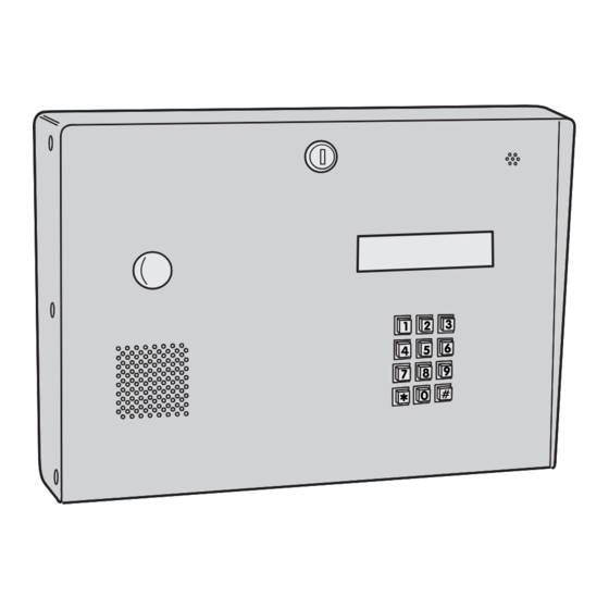
2. AE-1 COMPONENT LOCATIONS
TELEPHONE
MICROPHONE
LINE TERMINALS
MODULAR
& POSTAL KEY
TELEPHONE
SWITCH TERMINALS
JACK (HIDDEN)
BUSY INDICATOR
(LIGHTS WHEN AE-1 IS
COMMUNICATING OR WHEN
HYBRID LEVEL
PHONE LINE IS DISCONNECTED)
ADJUSTMENT
(FACTORY SET
DO NOT ADJUST)
SPEAKER
VOLUME
ADJUSTMENT
SPEAKER
CONNECTOR
AE-1 TO AM/II
INTERCONNECT
CABLE
ON-LINE INDICATOR
TEST JUMPER
(LIGHTS WHEN PHONE
(REMOVE TO
LINE IS ACTIVE)
HEAR UNIT DIAL)
INTRODUCTION
The Model AE-1 Telephone Entry Control Console is designed for use as a primary
access control device for gated communities, parking garages, office buildings,
apartments, dormitories, hotels/motels, commercial buildings and recreational facilities.
This unit is a fusion of Linear's full-featured Model AM/II Access Control System and
the Model AE-1 Telephone Entry Module. Housed in a locked, rugged stainless steel
enclosure, the AE-1 features a 12-key telephone style keypad, a backlit two-line
directory display, and a built-in microphone and speaker.
All of the outstanding AM/II access control system functions are available with the AE-1 in
addition to hands-free, full duplex telephone communications with tenants or authorized
personnel for granting access. Entry codes can also be typed directly on the keypad.
In a typical installation, the unit's memory would be programmed with each tenant's
name and directory code number. A visitor would use the
the directory names and code number for the desired party. Upon entering the directory
number, the AE-1 will automatically dial the tenant's telephone number and establish
two-way voice communication between the visitor and the tenant. The tenant will then
have the option to grant access to the guest by pressing a digit on their telephone.
In addition to the telephone entry, the AE-1 can grant access using various remote
devices that are commonly used with the AM/II. These devices include wireless
transmitters, proximity receivers, swipe card readers and remote keypads.
The output relays can be programmed to control electric door strikes, door & gate
operators, barrier gates. CCTV cameras can also be triggered by the output relays to
monitor the entry areas.
All of the programming functions of the AE-1 can be performed directly through the
unit's keypad. An optional telephone modem can be installed for easy remote
programming with a personal computer.
The AE-1 cabinet has provisions for installing a postal lock for keyed mail carrier access.
The postal lock can be programmed to activate any of the four output relays.
3. DETERMINE MOUNTING LOCATION
THE AE-1 SHOULD BE MOUNTED IN A WELL LIT LOCATION NEAR THE
CONTROLLED OPENING. WIRING ACCESS FOR POWER, TELEPHONE,
EARTH GROUND, CONTROL OUTPUT AND ANTENNA CO-AX MUST BE
AVAILABLE BEHIND THE MOUNTING LOCATION.
AREA
LIGHTING
AE-1
TELEPHONE
ENTRY SYSTEM
DISPLAY
CONTRAST
ADJUSTMENT
or # key on the AE-1 to view
*
CONTROLLED
ENTRY DOOR
1. SYSTEM COMPONENT LOCATIONS
AM/II ACCESS
CONTROL SYSTEM
SPEAKER
POSTAL LOCK
POSTAL LOCK
LOCATION
SWITCH
(LOCK OPTIONAL)
4. MOUNT CABINET
5 3/8"
5 3/8"
MOUNT CABINET WITH
SUITABLE HARDWARE FOR
MOUNTING SURFACE.
9 3/8"
USE TOGGLE BOLTS FOR
STUCCO WALL, WEDGE
ANCHORS OR EXPANSION
5 3/8"
5 3/8"
BOLTS FOR CONCRETE
WALL, LAG SCREWS FOR
WOOD WALL.
MOUNTING
LOCATION
MODEM
(OPTIONAL)
AE-1 TELEPHONE
ENTRY MODULE
MICROPHONE
(HIDDEN)
Advertisement
Table of Contents

Subscribe to Our Youtube Channel
Related Manuals for Linear AE-1


Summary of Contents for Linear AE-1
- Page 1 AE-1 features a 12-key telephone style keypad, a backlit two-line directory display, and a built-in microphone and speaker. All of the outstanding AM/II access control system functions are available with the AE-1 in addition to hands-free, full duplex telephone communications with tenants or authorized personnel for granting access.
- Page 2 Consumers should inquire from their selling dealer as to the nature of the dealer’s warranty, if any. There are no obligations or liabilities on the part of Linear Corporation for consequential damages arising out of or in connection with use or performance of this product or other indirect damages with respect to loss of property, revenue, or profit, or cost of removal, installation, or reinstallation.
Need help?
Do you have a question about the AE-1 and is the answer not in the manual?
Questions and answers