Table of Contents
Advertisement
Quick Links
AM-KP
Access
1
Control
4
Keypad
7
*
Installation
Instructions
2. PLAN INSTALLATION
PLAN THE LOCATIONS
FOR CONTROL AND
REMOTE DEVICES
PLAN CABLE RUNS
BETWEEN CONTROL
AND REMOTE DEVICES
CONTROLLER
AM-KP
ON
PEDESTAL
LOBBY
SERVICE
AM-KP
ACCESS
KEYPADS
BATH
BATH
CARD
READERS
(USING AM-CRI
INTERFACE)
COMPUTER
COMMERICAL
ROOM
INSTALLATION
V.P.
INTRODUCTION
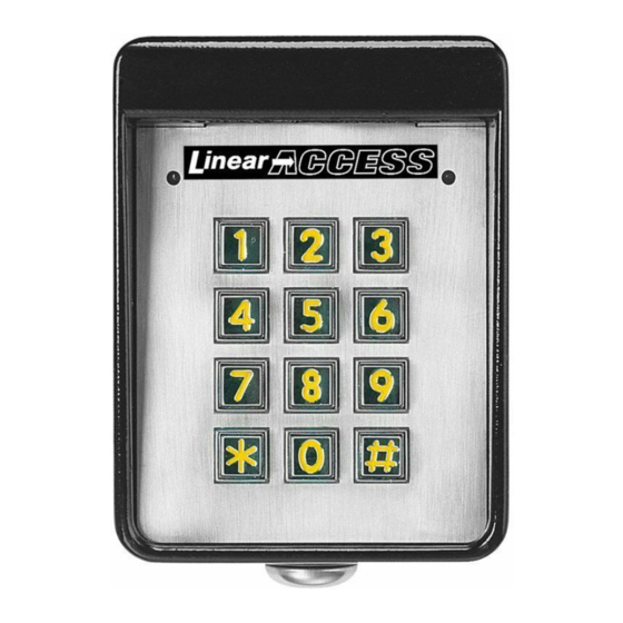
The AM-KP keypad is designed for use with Linear's AE1000Plus,
AE2000Plus, and AM3Plus access control systems. The keypad is housed
in a rugged cast aluminum enclosure. The die-cast keys have bright, easy-
to-read yellow graphics. Each key has a positive tactile "click" feel when
pressed. An internal sounder signals when a key is pressed.
The keypad can be mounted to a pedestal or directly to a wall. A keylock
secures the keypad to the mounting backplate.
An incandescent panel lamp lights the keypad for nighttime use. Red, green
and yellow indicators show power, access and lockout conditions.
2
3
The AM-KP is normally powered from the controller, or can be powered
5
6
locally from a 12 VDC power supply. Robust static and lightning protection
8
9
circuits safeguard the keypad's electronics.
0
#
A rotary switch selects the keypad's PBUS device address. Each PBUS
device connected to the controller must be set to a different PBUS device
address.
3. MOUNT BACKPLATE
APARTMENTS
APARTMENT GATE
INSTALLATION
PEDESTAL
CONTROLLER
CHIEF
ENG.
LAB
ENGINEERING
COPIER
AREA
WALL MOUNTING
STOR.
SALES
USE CONCRETE
WEDGE ANCHORS
OR MOLLY ANCHORS
V.P.
PURCH.
SALES
MOUNT BACKPLATE WITH
SECURITY BOLTS AND LOCKNUTS
1. AM-KP FEATURES
NIGHT LIGHT
1
2
3
RED/GREEN POWER/ACCESS
4
5
6
INDICATOR
7
8
9
*
0
#
POWER/DATA
TERMINALS
PBUS
DEVICE
ADDRESS
SELECTOR
(1-6)
SOUNDER
KEYLOCK
4. ROUTE CABLE
EACH AM-KP KEYPAD EQUALS 9 LOAD UNITS
CABLE LENGTH FORMULA FOR EACH KEYPAD USED IN SYSTEM
CABLE RUN
CABLE TYPE
300 FEET MAXIMUM
BELDEN 9931 (24 AWG)
FEET x LOAD UNITS < 3,000 MAXIMUM
500 FEET MAXIMUM
WEICO 9405 (20 AWG)
FEET x LOAD UNITS < 10,000 MAXIMUM
HOMERUN WIRE
EACH KEYPAD
(1000 FEET WIRE MAXIMUM
ALLOWED IN SYSTEM)
YELLOW "LOCKOUT"
INDICATOR
FORMULA
Advertisement
Table of Contents

Subscribe to Our Youtube Channel
Related Manuals for Linear AM-KP


Summary of Contents for Linear AM-KP
- Page 1 Access Control The AM-KP is normally powered from the controller, or can be powered locally from a 12 VDC power supply. Robust static and lightning protection Keypad circuits safeguard the keypad’s electronics.
- Page 2 USE KEY TO LOCK KEYPAD FOR LOCAL POWER, DISCONNECT RED WIRE FROM "PWR" CONNECTION ON AM-KP AND CONNECT EXTERNAL 12 VDC SUPPLY (+ TO PWR & - TO GND) NOTE: CONTROLLER MUST BE CONNECTED TO AM-KP "GND" 8. PROGRAM SYSTEM 9.
Need help?
Do you have a question about the AM-KP and is the answer not in the manual?
Questions and answers