
Related Manuals for IBASE Technology MI836F


Summary of Contents for IBASE Technology MI836F
- Page 1 MI836F ® ® Intel Atom (x6000 Series) Mini-ITX Motherboard User’s Manual Version 1.0 (December 2022)
- Page 2 No part of this publication may be reproduced, copied, stored in a retrieval system, translated into any language or transmitted in any form or by any means, electronic, mechanical, photocopying, or otherwise, without the prior written consent of IBASE Technology, Inc. (hereinafter referred to as “IBASE”). Disclaimer IBASE reserves the right to make changes and improvements to the products described in this document without prior notice.
- Page 3 0.1% by weight (1000 ppm) except for cadmium, limited to 0.01% by weight (100 ppm). • Lead (Pb) • Mercury (Hg) • Cadmium (Cd) • Hexavalent chromium (Cr6+) • Polybrominated biphenyls (PBB) • Polybrominated diphenyl ether (PBDE) MI836F User’s Manual...
- Page 4 Danger of explosion if the internal lithium-ion battery is replaced by an incorrect type. Replace only with the same or equivalent type recommended by the manufacturer. Dispose of used batteries according to the manufacturer’s instructions or recycle them at a local recycling facility or battery collection point. MI836F User’s Manual...
- Page 5 Software in use (such as OS and application software, including the version numbers) If repair service is required, you can download the RMA form at http://www.ibase.com.tw/english/Supports/RMAService/. Fill out the form and contact your distributor or sales representative. MI836F User’s Manual...
-
Page 6: Table Of Contents
SUS_CLK-OUT (J10) ............28 2.3.10 Audio SPDIF-OUT (J12) ............28 2.3.11 Front Panel Settings Connector (J15) ........29 2.3.12 Audio Amplifier Connector (J16) .......... 30 2.3.13 Audio Connector (J17)............31 2.3.14 Digital I/O Connector (J19) ..........32 MI836F User’s Manual... - Page 7 Advanced Settings ................47 Chipset Settings .................58 Security Settings ................61 Boot Settings ..................63 Save & Exit Settings ................64 Appendix ..................65 I/O Port Address Map ................66 Interrupt Request Lines (IRQ) ............68 Watchdog Timer Configuration ............69 On-Board Connector Types ...............73 MI836F User’s Manual...
-
Page 9: Chapter 1 General Information
Chapter 1 General Information The information provided in this chapter includes: • Features • Packing List • Specifications • Block Diagram • Product View • Dimensions... -
Page 10: Introduction
Introduction MI836F is a Mini-ITX motherboard based on the Atom x6000E series processors with either LVDS or eDP graphics interface support. Other graphics display ports available are VGA and HDMI 2.0b. Two DDR4 SO-DIMM sockets support up to 32GB of 3200MHz memory. Two 2.5G LAN are on board as well as 3x USB 3.1 and four USB 2.0 and M.2 Key E and... -
Page 11: Packing List
Disk (including chipset drivers) • This User’s Manual Optional Accessories IBASE provides the optional accessories listed below. • Audio Cable (Audio-34) • USB Cable (USB-29) • USB Cable (USB2-4) • COM Port Cable (PK1H) • 60W Power Adaptor MI836F User’s Manual... -
Page 12: Specifications
Timer BIOS AMI BIOS Reserved firmware TPM (fTPM) EuP / ErP Compliant Dimensions 170 x 170 mm (6.7” x 6.7”) RoHS • Microsoft Windows 10 (64-bit) Operating System • Linux Ubuntu (64-bit) CE, FCC Class A Certification MI836F User’s Manual... - Page 13 • 1 x M.2 Key E, type 2230, with USB 2.0 / PCIe(x1) • mPCIe Environment • Operating temperature: -40 ~ 70 °C Temperature Relative 0 ~ 90 %, non-condensing at 60 °C Humidity All specifications are subject to change without prior notice. MI836F User’s Manual...
-
Page 14: Block Diagram
Block Diagram MI836F User’s Manual... -
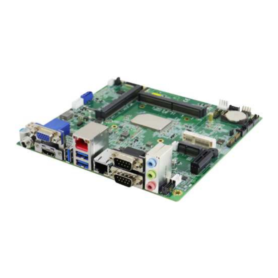
Page 15: Product View
General Information Product View Top View MI836F User’s Manual... - Page 16 Bottom View MI836F User’s Manual...
- Page 17 General Information I/O View Name Name CN3 DC Power Input CN7 LAN Port CN4 VGA & HDMI Ports CN8 COM1/COM2 Ports CN5 USB 3.1 Port CN9 Audio (Line-out, Line-in, Mic) CN6 LAN & 2x USB 3.1 Ports MI836F User’s Manual...
-
Page 18: Dimensions
Dimensions MI836F User’s Manual... -
Page 19: Chapter 2 Hardware Configuration
Chapter 2 Hardware Configuration This section provides information on jumper settings and connectors on the board in order to set up a workable system. The topics covered are: • Memory installation • Jumper and connector locations • Jumper settings and information of connectors... -
Page 20: Installations
Gently push the module in an upright position until the clips of the slot close to hold the module in place when the module touches the bottom of the slot. To remove the module, press the clips outwards with both hands, and the module will pop-up. MI836F User’s Manual... -
Page 21: Setting The Jumpers
1 2 3 When two pins of a jumper are encased in a jumper cap, this jumper is closed, i.e. turned On. When a jumper cap is removed from two jumper pins, this jumper is open, i.e. turned Off. MI836F User’s Manual... -
Page 22: Jumper & Connector Locations
Jumper & Connector Locations MI836F MI836F User’s Manual... -
Page 23: Clear Cmos Data (Sw1)
Clear CMOS Data Clear ME Register EDP Panel Power Select LVDS Panel Brightness Select LVDS Panel Power Select ATX / AT Power Select 2.2.1 Clear CMOS Data (SW1) Function Pin closed Normal P1-OFF (default) Clear P1-ON CMOS MI836F User’s Manual... -
Page 24: Clear Me Register (Sw1)
2.2.2 Clear ME Register (SW1) Function Pin closed Normal P2-OFF (default) Clear ME P2-ON MI836F User’s Manual... -
Page 25: Edp Panel Power Selection (Jp1)
Hardware Configuration 2.2.3 EDP Panel Power Selection (JP1) Function Pin closed Illustration 3.3V (default) MI836F User’s Manual... -
Page 26: Lvds Panel Brightness Selection (Jp2)
2.2.4 LVDS Panel Brightness Selection (JP2) Function Pin closed Illustration 3.3V (default) MI836F User’s Manual... -
Page 27: Lvds Panel Power Selection (Jp3)
Hardware Configuration 2.2.5 LVDS Panel Power Selection (JP3) Function Pin closed Illustration 3.3V (default) MI836F User’s Manual... -
Page 28: Atx & At Power Mode Selection (Jp4)
2.2.6 ATX & AT Power Mode Selection (JP4) Function Pin closed Illustration ATX Mode (default) AT Mode MI836F User’s Manual... -
Page 29: Connectors Quick Reference
Audio Amplifier Connector Audio Connector Digital I/O USB 2.0 Connector J20, J23 CPU PWM Fan Power Connector CPU_FAN1 VGA & HDMI Ports USB 3.1 Port LAN & 2x USB 3.1 Ports LAN Port Audio (Line-out, Line-in, Mic) MI836F User’s Manual... -
Page 30: Com1 & Com2 Rs-232/422/485 Ports (Cn8)
RTS, Request to send TXD, Transmit data CTS, Clear to send DTR, Data terminal ready RI, Ring indicator Ground Signal Name RS-232 RS-422 RS-485 DATA- DATA+ Ground Ground Ground *COM1 & COM2 support jumperless setting, via BIOS setting. MI836F User’s Manual... -
Page 31: Com3 & Com4 Rs-232 Ports (J22, J21)
COM3 & COM4 RS-232 Ports (J22, J21) Signal Name Signal Name DCD, Data carrier detect RXD, Receive data TXD, Transmit data DTR, Data terminal ready Ground DSR, Data set ready RTS, Request to send CTS, Clear to send RI, Ring indicator MI836F User’s Manual... -
Page 32: Edp Connector (Cn2)
2.3.3 eDP Connector (CN2) Signal Name Signal Name VDD_EDP VDD_EDP VDD_EDP VDD_EDP VDD_EDP EDP_HDP TXN3 TXP3 TXN2 TXP2 TXN1 TXP1 TXN0 TXP0 AUXP AUXN VCC3 BL_PWR1 VCC5 BKLT_CTRL BKLT_EN BL_PWR2 VCC3 EDP_CK EDP_DATA MI836F User’s Manual... -
Page 33: Dc Power Input Connector (Cn3)
Hardware Configuration 2.3.4 DC Power Input Connector (CN3) Signal Name +12V~24V Ground 2.3.5 LCD Backlight Connector (J1) Signal Name Signal Name +12V Brightness Control Backlight Enable Ground MI836F User’s Manual... -
Page 34: Sata Hdd Power Connector (J2)
2.3.6 SATA HDD Power Connector (J2) Signal Name Signal Name Ground Ground +12V 2.3.7 DC Power Input Connector (J3) Signal Name Signal Name Ground 12V~24V Ground 12V~24V MI836F User’s Manual... -
Page 35: Lvds Connector (J4-Cha, J7-Chb)
Hardware Configuration 2.3.8 LVDS Connector (J4-CHA, J7-CHB) Signal Name Signal Name TX0P TX0N Ground Ground TX1P TX1N Ground Ground TX2P TX2N Ground Ground CLKP CLKN Ground Ground TX3P TX3N Power Power MI836F User’s Manual... -
Page 36: Sus_Clk-Out (J10)
2.3.9 SUS_CLK-OUT (J10) Signal Name SUS_CLK-OUT Ground 2.3.10 Audio SPDIF-OUT (J12) Signal Name SPDIF-OUT Ground MI836F User’s Manual... -
Page 37: Front Panel Settings Connector (J15)
Orientation is not required when making a connection to this header. • Power LED (Pins 7 and 8) This connector connects to the system power LED on control panel. This LED will light when the system turns on. MI836F User’s Manual... -
Page 38: Audio Amplifier Connector (J16)
2.3.12 Audio Amplifier Connector (J16) Signal Name SPK_L+ SPK_L- SPK_R- SPK_R+ MI836F User’s Manual... -
Page 39: Audio Connector (J17)
Hardware Configuration 2.3.13 Audio Connector (J17) Signal Name Signal Name Lineout_L Lineout_R JD_FRONT Ground LINEIN_L Linein_R JD_LINEIN Ground MIC_L MIC-R JD_MIC1 Ground MI836F User’s Manual... -
Page 40: Digital I/O Connector (J19)
2.3.14 Digital I/O Connector (J19) Signal Name Signal Name Ground OUT3 OUT1 OUT2 OUT0 MI836F User’s Manual... -
Page 41: Usb 2.0 Connector (J20, J23)
Hardware Configuration 2.3.15 USB 2.0 Connector (J20, J23) Signal Name Signal Name Ground Ground 2.3.16 CPU PWM Fan Power Connector (CPU_FAN1) Signal Name Signal Name Ground Rotation detection +12V Control Remarks: PWM only MI836F User’s Manual... - Page 42 This page is intentionally left blank. MI836F User’s Manual...
-
Page 43: Chapter 3 Drivers Installation
Chapter 3 Drivers Installation This chapter introduces installation of the following drivers: • ® Intel Chipset Software Installation Utility • HD Graphics Driver • HD Audio Driver • ® Intel Management Engine Drivers Installation • LAN Driver... -
Page 44: Introduction
INF files for Plug & Play function for Intel chipset components. Follow the instructions below to complete the installation. Insert the disk enclosed in the package with the board. Click Intel on the left pane and then Intel(R) Elkhartlake Chipset Drivers on the right pane. MI836F User’s Manual... -
Page 45: Hd Graphics Driver Installation
Next to continue. Accept the software license agreement. On the Readme File Information screen, click Install. When you have completed the setup process, click Fiinish. HD Graphics Driver Installation Click Intel(R) Elkhartlake Chipset Drivers on the right pane. MI836F User’s Manual... - Page 46 Click Intel(R) Elkhartlake Graphics Driver. Click Begin Installation. Click I agree. MI836F User’s Manual...
- Page 47 Driver Installation Click Start to begin installing the new graphics driver. When installation is complete, restart your system in order to apply the driver changes. MI836F User’s Manual...
-
Page 48: Hd Audio Driver Installation
Click Intel(R) Elkhartlake Chipset Drivers on the right pane. Click Realtek High Definition Audio Driver on the right pane. The InstallShield Wizard will start installation of the Realtek Audio Driver. When the installation has been completed, restart the computer. MI836F User’s Manual... -
Page 49: Intel ® Management Engine Drivers Installation
When the Welcome screen appears, click Next. Accept the license agreement, click Next. To install to the default folder, click Next or click Change to choose another destination folder. When the components have been successfully installed, click Finish. MI836F User’s Manual... -
Page 50: Lan Driver Installation
LAN Driver Installation Click LAN Card on the left pane and then Intel LAN Controller Drivers on the right pane. Click Intel(R) I21x / I22x Gigabit Network Drivers. Click Install Drivers and Software. MI836F User’s Manual... - Page 51 When the Welcome screen appears, click Next. Accept the license agreement and click Next. On the Setup Options screen, select the desired program features and click Next. The wizard is ready for installation. Click Install. Install wizard has completed the installation. Click Finish. MI836F User’s Manual...
-
Page 52: Chapter 4 Bios Setup
Chapter 4 BIOS Setup This chapter describes the different settings available in the AMI BIOS that comes with the board. The topics covered in this chapter are as follows: • Main Settings • Advanced Settings • Chipset Settings • Boot Settings •... -
Page 53: Introduction
These defaults have been carefully chosen by both AMI and your system manufacturer to provide the absolute maximum performance and reliability. Changing the defaults could make the system unstable and crash in some cases. MI836F User’s Manual... -
Page 54: 4.3 Main Settings
System Language Chooses the system default language. Sets the date. Use the <Tab> key to switch System Date between the date elements. Set the time. Use the <Tab> key to switch System Time between the time elements. MI836F User’s Manual... -
Page 55: 4.4 Advanced Settings
Displays super IO chip parameters. Configuration Fintek Super IO Shows super IO monitor hardware status. Hardware Monitor USB Configuration Displays USB configuration parameters. Network Stack Netowrk Stack settings. Configuration [1]: LVDS (eDP/DP) Configuration is available depending on the motherboard model. MI836F User’s Manual... - Page 56 4.4.1 CPU Configuration BIOS Setting Description Intel (VMX) Enables / Disables a VMM to utilize the additional Virtualization hardware capabilities provided by Vanderpool Technology Technology. MI836F User’s Manual...
- Page 57 Description Enables / Disables BIOS support for security Security Device device. OS will not show security device. TCG Support EFI protocol and INTIA interface will not be available. SHA-1 PCR Bank Enables / Disables SHA-1 PCR Bank. MI836F User’s Manual...
- Page 58 • TPM 2.0 will restrict support to TPM 2.0 Device Select devices only. • Auto will support both with the default being set to TPM 2.0 deices if not found, and TPM 1.2 device will be enumerated. MI836F User’s Manual...
- Page 59 (OS/S4 Sleep State). This option may be not effective Hibernation with some OS. Selects an ACPI sleep state where the system will enter ACPI Sleep when the Suspend button is pressed. State Options: Suspend Disabled, S3 (Suspend to RAM) MI836F User’s Manual...
- Page 60 4.4.5 LVDS (eDP/DP) Configuration Note: LVDS (eDP/DP) configuration is only available for MI836F series and MI836EF. BIOS Setting Description LVDS (eDP/DP) Support Enables / Disables LVDS (eDP/DP). MI836F User’s Manual...
- Page 61 Run SMART Self Test on all HDDs during SMART Self Test POST. 4.4.7 Fintek Super IO Configuration BIOS Setting Description Power Failure Options: Always on, Always off Serial Port Configuration Sets parameters of Serial Ports. 4.4.7.1. Serial Port 1 Configuration MI836F User’s Manual...
- Page 62 4.4.7.2. Serial Port 2 Configuration 4.4.7.3. Serial Port 3 Configuration 4.4.7.4. Serial Port 4 Configuration MI836F User’s Manual...
- Page 63 The values are read-only values as monitored by the system and show the PC health status. CPU Shutdown Options: Disabled / 70 °C / 75 °C / 80 °C / 85 °C / Temperature 90 °C / 95 °C MI836F User’s Manual...
- Page 64 Hub descriptor. Options: Auto / Manual Mass storage device emulation type. AUTO enumerates devices according to their media USB DISK 3.0 PMAP format. Optical drives are emulated as CDROM drives with no medial will be emulated according to a drive type. MI836F User’s Manual...
- Page 65 PXE boot wait time the PXE boot. Use either +/- or numeric keys to set the value. Number of times the presence of media will be Nedua detect ciybt checked. Use either +/- or numeric keys to set the value. MI836F User’s Manual...
-
Page 66: 4.5 Chipset Settings
BIOS Setting Description System Agent (SA) System Agent (SA) parameters Configuration PCH-IO Configuration PCH parameters 4.5.1 System Agent (SA) Configuration BIOS Setting Description Graphics Configures the graphics settings. Configuration VT-d Checks if VT-d function on MCH is supported. MI836F User’s Manual... - Page 67 Sets the aperture size as 128 MB, 256 MB, 512 MB, 1024 MB or 2048 MB. Note: Above 4 GB MMIO BIOS assignment is Aperture Size automatically enabled when selecting 2048 MB aperture. To use this feature, disable CSM support. MI836F User’s Manual...
- Page 68 Description SATA Controller(s) Enables / Disables the SATA device. Determines how SATA controller(s) operate. SATA Mode Selection Options: AHCI Serial ATA Ports Enables / Disables serial ports. SATA Ports Hot Plug Designate the port as Hot Pluggable. MI836F User’s Manual...
-
Page 69: 4.6 Security Settings
Configures Secure Boot. 4.6.1 Secure Boot BIOS Setting Description Secure Boot feature is Active if Secure Boot is enabled. Platform Key (PK) Is enrolled and system is in Secure Boot User mode. The mode change requires platform reset. MI836F User’s Manual... - Page 70 Restore DB variable to factory defaults. Enroll factory defaults or load certificates from a file. 1. Public key certificate: EFI_SIGNATIRE_LIST, EFI_CERT_X509 (DER), EFI_CERT_RSA2048 Secure Boot (bin), EFI_CERT_SHAXXX variable 2. Authenticated UEFI Variable 3. EFI PE/COFF image (SHA256) Key source: factory, external, mixed MI836F User’s Manual...
-
Page 71: 4.7 Boot Settings
Number of seconds to wait for setup activation key. Setup Prompt Timeout 65535(0xFFFF) means indefinite waiting. Bootup NumLock State Selects the keyboard NumLock state. Quiet Boot Enables / Disables Quiet Boot option. Boot Option Priorities Sets the system boot order. MI836F User’s Manual... -
Page 72: 4.8 Save & Exit Settings
Restores / Loads defaults values for all the setup Restore Defaults options. Save as User Defaults Saves the changes done so far as User Defaults. Restore User Defaults Restores the user defaults to all the setup options. MI836F User’s Manual... -
Page 73: Appendix
Appendix This section provides the mapping addresses of peripheral devices, the sample code of watchdog timer configuration, and types of on-board connectors. -
Page 74: I/O Port Address Map
Communications Port (COM2) 0x000003E8-0x000003EF Communications Port (COM3) 0x000002E8-0x000002EF Communications Port (COM4) 0x00001800-0x000018FE Motherboard resources 0x00003090-0x00003097 Standard SATA AHCI Controller 0x00003080-0x00003083 Standard SATA AHCI Controller 0x00003060-0x0000307F Standard SATA AHCI Controller 0x00000020-0x00000021 Programmable interrupt controller 0x00000024-0x00000025 Programmable interrupt controller MI836F User’s Manual... - Page 75 Programmable interrupt controller 0x000004D0-0x000004D1 Programmable interrupt controller 0x00001854-0x00001857 Motherboard resources 0x00000000-0x00000CF7 PCI Express Root Complex 0x00000D00-0x0000FFFF PCI Express Root Complex 0x0000EFA0-0x0000EFBF Intel(R) SMBus Controller - 4B23 0x00002000-0x000020FE Motherboard resources 0x00003000-0x0000303F Intel(R) UHD Graphics 0x00000040-0x00000043 System timer 0x00000050-0x00000053 System timer MI836F User’s Manual...
-
Page 76: Interrupt Request Lines (Irq)
Intel(R) USB 3.10 eXtensible Host Controller - 1.20 IRQ 4294967293 (Microsoft) IRQ 55~204 Microsoft ACPI-Compliant System IRQ 256~511 Microsoft ACPI-Compliant System IRQ 4294967291 Intel(R) Management Engine Interface #1 IRQ 4294967292 Intel(R) UHD Graphics IRQ 0 System timer MI836F User’s Manual... -
Page 77: Watchdog Timer Configuration
**endptr; char SIO; printf("Fintek 81866 watch dog program\n"); SIO = Init_F81866(); if (SIO == 0) printf("Can not detect Fintek 81866, program abort.\n"); return(1); }//if (SIO == 0) if (argc != 2) printf(" Parameter incorrect!!\n"); return (1); MI836F User’s Manual... - Page 78 DisableWDT(void) unsigned char bBuf; Set_F81866_LD(0x07); //switch to logic device 7 bBuf = Get_F81866_Reg(0xFA); bBuf &= ~0x01; Set_F81866_Reg(0xFA, bBuf); //disable WDTO output bBuf = Get_F81866_Reg(0xF5); bBuf &= ~0x20; bBuf |= 0x40; Set_F81866_Reg(0xF5, bBuf); //disable WDT //--------------------------------------------------------------------------- //--------------------------------------------------------------------------- MI836F User’s Manual...
- Page 79 Init_Finish; F81866_BASE = 0x00; result = F81866_BASE; Init_Finish: return (result); //--------------------------------------------------------------------------- void Unlock_F81866 (void) outportb(F81866_INDEX_PORT, F81866_UNLOCK); outportb(F81866_INDEX_PORT, F81866_UNLOCK); //--------------------------------------------------------------------------- void Lock_F81866 (void) outportb(F81866_INDEX_PORT, F81866_LOCK); //--------------------------------------------------------------------------- void Set_F81866_LD( unsigned char LD) Unlock_F81866(); outportb(F81866_INDEX_PORT, F81866_REG_LD); outportb(F81866_DATA_PORT, LD); Lock_F81866(); MI836F User’s Manual...
- Page 80 #define F81866_DATA_PORT (F81866_BASE+1) //--------------------------------------------------------------------------- #define F81866_REG_LD 0x07 //--------------------------------------------------------------------------- #define F81866_UNLOCK 0x87 #define F81866_LOCK 0xAA //--------------------------------------------------------------------------- unsigned int Init_F81866(void); void Set_F81866_LD( unsigned char); void Set_F81866_Reg( unsigned char, unsigned char); unsigned char Get_F81866_Reg( unsigned char); //--------------------------------------------------------------------------- #endif // F81866_H MI836F User’s Manual...
-
Page 81: On-Board Connector Types
2.54 mm-pitch Connector (female) J4-CHA, LVDS Connector J7-CHB DF20F-20DP-1V DF20A-20DS-1C Fan Power TECHBEST Molex CPU_FAN1 Connector W2-03I104132S1WT(A)-L 47054-1000 E-CALLl SATA HDD Power 0110-071-040 XHP-4 E-CALL LCD Backlight 0110-161-040 PHR-4. Hirose Audio DF11-12DP-2DSA DF11-12DS-2C E-CALL Audio Amplifier 0110-161-040 PHR-4. MI836F User’s Manual...
Need help?
Do you have a question about the MI836F and is the answer not in the manual?
Questions and answers