
Related Manuals for IBASE Technology MI811F-420


Summary of Contents for IBASE Technology MI811F-420
- Page 1 MI811F Series ® ® ® Intel Pentium & Celeron Mini-ITX Motherboard User’s Manual Version 1.1 (Sep. 2017)
- Page 2 No part of this publication may be reproduced, copied, stored in a retrieval system, translated into any language or transmitted in any form or by any means, electronic, mechanical, photocopying, or otherwise, without the prior written consent of IBASE Technology, Inc. (hereinafter referred to as “IBASE”). Disclaimer IBASE reserves the right to make changes and improvements to the products described in this document without prior notice.
- Page 3 Compliance This product has passed CE tests for environmental specifications and limits. This product is in accordance with the directives of the European Union (EU). In a domestic environment, this product may cause radio interference in which case users may be required to take adequate measures.
-
Page 4: Important Safety Information
Important Safety Information Carefully read the precautions before using the board. Environmental conditions: • Use this product in environments with ambient temperatures between 0˚C and 60˚C. • Do not leave this product in an environment where the storage temperature may be below -20° C or above 80° C. To prevent from damages, the product must be used in a controlled environment. -
Page 5: Warranty Policy
Warranty Policy • IBASE standard products: 24-month (2-year) warranty from the date of shipment. If the date of shipment cannot be ascertained, the product serial numbers can be used to determine the approximate shipping date. • -party parts: 12-month (1-year) warranty from delivery for the 3 -party parts that are not manufactured by IBASE, such as CPU, CPU cooler, memory, storage devices, power adapter, panel and touchscreen. - Page 6 Table of Contents Compliance ..................iii Important Safety Information ............iv Warranty Policy ................v Technical Support & Services ............v Chapter 1 General Information ..........1 Introduction ..................2 Features ....................2 Packing List ..................3 Optional Accessories ................3 Specifications ..................
- Page 7 2.5.5 HDMI Port (CN6, CN7) ............27 2.5.6 Audio Jack (CN10) ..............27 2.5.7 DVI-D Connector (J11) ............28 2.5.8 SATA III Port (CN8, CN9) ............29 2.5.9 Mini-PCIe Slot for mSATA (J8) ..........29 2.5.10 Mini-PCIe Slot (J7) ..............30 2.5.11 Panel Inverter Connector (J2) ..........30 2.5.12 LVDS Connector (J3, J4) .............31 2.5.13...
- Page 8 4.4.6 CPU Configuration ............... 65 4.4.7 AMI Graphic Output Protocol Policy ........66 4.4.8 Network Stack Configuration ..........67 4.4.9 CSM Configuration ............... 68 4.4.10 USB Configuration ............... 69 Chipset Settings ................70 4.5.1 South Cluster Configuration ..........70 Security Settings ................75 Boot Settings ..................
-
Page 9: Chapter 1 General Information
Chapter 1 General Information The information provided in this chapter includes: • Features • Packing List • Optional Accessories • Specifications • Block Diagram • Board Overview • Board Dimensions... -
Page 10: Introduction
Introduction ® ® MI811F is a Mini-ITX motherboard based on the platform of Intel Pentium ® N4200 or Celeron N3350. This board features HDMI at I/O coastline, on-board headers for LVDS, eDP and 24-bit dual channel LVDS interfaces for video display. You can use either eDP or LVDS interface. It is able to be operated at the ambient operating temperature ranging from 0 ~ 60 °C, and even from -20 ~ 80 °C for storage. -
Page 11: Packing List
General Information Packing List Your MI811F package should include the items listed below. If any of the items below is missing, contact the distributor or dealer from whom you purchased the product. • MI811F • IO Shield • SATA cable (SATA-5 for ATX power connector;... -
Page 12: Specifications
Specifications Product MI811F-420 MI811F-420D MI811F-335 MI811F-335D Name Mini-ITX Motherboard Form Factor System • Windows 10 Enterprise (64-bit) Operating • Windows 10 IoT Core (64-bit) System • Linux Ubuntu ® ® ® ® Intel Pentium QC N4200 Intel Celeron DC N3350... - Page 13 General Information 170 x 170 mm (6.7” x 6.7”) Dimensions RoHS CE, FCC Class B, LVD Certification I/O Ports • 1 x HDMI (1.4b, CN7 connector), 3840 x 2160 at 30 Hz • 1 x HDMI (1.4b, CN6 connector) or DVI-D, 3840 x 2160 at 30 •...
- Page 14 • 1 x Mini PCIe slot (full-size) for mSATA Expansion • 1 x Mini PCIe slot (half-size) with USB Slots • 1 x PCIe (x1) slot Environment Operation: 0 ~ 60 °C (32 ~ 140 °F) • Temperature Storage: -20 ~ 80 °C (-4 ~ 176 °F) •...
-
Page 15: Block Diagram
General Information Block Diagram MI811F Series User’s Manual... -
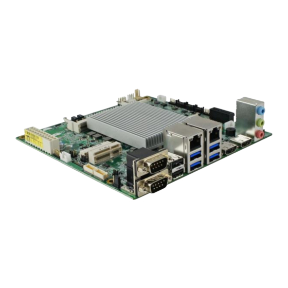
Page 16: Overview
Overview Top View Photo of MI811F (ATX power) *The photos above are for reference only. Some minor components may differ. MI811F Series User’s Manual... - Page 17 General Information I/O View Name Name COM1 RS-232/422/485 Port HDMI Port (given the precedence over the DVI-D connector, J11) COM2 RS-232 Port HDMI Port USB 2.0 Port Line-In LAN Port (GbE) Line-Out USB 3.0 Port Microphone-Input MI811F Series User’s Manual...
-
Page 18: Dimensions
Dimensions 165.1 33.02 10.16 35.52 31.05 28.38 MI811F Series User’s Manual... -
Page 19: Chapter 2 Hardware Configuration
Chapter 2 Hardware Configuration This section provides information on jumper settings and connectors on the MI811F in order to set up a workable system. On top of that, you will also need to install crucial pieces such as the CPU and the memory before using the product. The topics covered are: •... -
Page 20: Essential Installations Before You Begin
Essential Installations Before You Begin Follow the instructions below to install the memory. 2.1.1 Installing the Memory To install the modules, locate the memory slot on the board and perform the following steps: Align the key of the memory module with that on the memory slot and insert the module slantwise. -
Page 21: Setting The Jumpers
Hardware Configuration Setting the Jumpers Set up and configure your MI811F by using jumpers for various settings and features according to your needs and applications. Contact your supplier if you have doubts about the best configuration for your use. 2.2.1 How to Set Jumpers Jumpers are short-length conductors consisting of several metal pins with a non-conductive base mounted on the circuit board. -
Page 22: Jumper & Connector Locations
Jumper & Connector Locations Board diagram of MI811F Note: J5 is only available for MI811F-420 & MI811F-335 (ATX power types). J6, J14, J15 is only available for MI811F-420D & MI811F-335D (DC-In power types). MI811F Series User’s Manual... - Page 23 Hardware Configuration Board diagram of MI811F MI811F Series User’s Manual...
-
Page 24: Jumpers Quick Reference
Jumpers Quick Reference Function Jumper Name Page LVDS Panel Power Selection Panel Output Selection Panel Backlight Control Selection SRTC Register Clearance CMOS Data Clearance eDP Backlight Power Selection eDP Panel Power Selection JP10 Factory Use Only 2.4.1 LVDS Panel Power Selection (JP1) Function Pin closed Illustration... -
Page 25: Panel Output Selection (Jp3)
Hardware Configuration 2.4.2 Panel Output Selection (JP3) Function Pin closed Illustration eDP Panel LVDS Panel (default) MI811F Series User’s Manual... -
Page 26: Panel Backlight Control Selection (Jp4)
2.4.3 Panel Backlight Control Selection (JP4) Function Pin closed Illustration 3.3V Open (default) Close MI811F Series User’s Manual... -
Page 27: Srtc Register Clearance (Jp6)
Hardware Configuration 2.4.4 SRTC Register Clearance (JP6) Function Pin closed Illustration Normal (default) Clear SRTC MI811F Series User’s Manual... -
Page 28: Cmos Data Clearance (Jp7)
2.4.5 CMOS Data Clearance (JP7) Function Pin closed Illustration Normal (default) Clear CMOS MI811F Series User’s Manual... -
Page 29: Edp Backlight Power Selection (Jp9)
Hardware Configuration 2.4.6 eDP Backlight Power Selection (JP9) Function Pin closed Illustration (default) MI811F Series User’s Manual... -
Page 30: Edp Panel Power Selection (Jp10)
2.4.7 eDP Panel Power Selection (JP10) Function Pin closed Illustration 3.3V (default) MI811F Series User’s Manual... -
Page 31: Connectors Quick Reference
Hardware Configuration Connectors Quick Reference Function Connector Name Page eDP Connector COM1 RS-232/422/485 Port & COM2 RS-232 Port Dual USB 2.0 Port Dual USB 3.0 Port & LAN Port CN4, CN5 CN6 (shared with J11), HDMI Port Audio Jack CN10 DVI-D Connector J11 (chared with CN6) SATA III Port... -
Page 32: Edp Connector (Cn1)
2.5.1 eDP Connector (CN1) Assignment Assignment Ground BL_PWR BL_PWR VDD_eDP BL_PWR VDD_eDP BL_PWR Ground AUX_N AUX_P BRIGHTNESS Ground BKLT_EN TX0_P Ground TX0_N Ground Ground Ground TX1_P Ground TX1_N Ground Ground MI811F Series User’s Manual... -
Page 33: Com1 Rs-232/422/485 Port & Com2 Rs-232 Port (Cn2)
Hardware Configuration 2.5.2 COM1 RS-232/422/485 Port & COM2 RS-232 Port (CN2) COM1: COM2: COM1 RS-232/422/485 port is jumper-less and configurable in BIOS. Assignment Assignment DCD, Data carrier detect DSR, Data set ready RXD, Receive data RTS, Request to send TXD, Transmit data CTS, Clear to send DTR, Data terminal ready RI, Ring indicator... -
Page 34: Dual Usb 2.0 Port (Cn3)
COM2 RS-232 port: Assignment Assignment DCD, Data carrier detect DSR, Data set ready RX, Receive RTS, Request to send TX, Transmit CTS, Clear to send DTR, Data terminal ready RI, Ring indicator Ground 2.5.3 Dual USB 2.0 Port (CN3) 2.5.4 Dual USB 3.0 Port &... -
Page 35: Hdmi Port (Cn6, Cn7)
Hardware Configuration 2.5.5 HDMI Port (CN6, CN7) CN6: shared with J11 CN7: (CN6 is the 1 priority.) 2.5.6 Audio Jack (CN10) MI811F Series User’s Manual... -
Page 36: Dvi-D Connector (J11)
2.5.7 DVI-D Connector (J11) J11: shared with CN6 (CN6 HDMI Port is the 1 priority.) Assignment Assignment DATA1_P DATA1_N Ground Ground CLK_P CLK_N Ground Ground DATA2_P DATA2_N Ground Ground DATA0_P DATA0_N SCLK MI811F Series User’s Manual... -
Page 37: Sata Iii Port (Cn8, Cn9)
Hardware Configuration 2.5.8 SATA III Port (CN8, CN9) CN8: shared with J8 CN9: (CN8 is the 1 priority) 2.5.9 Mini-PCIe Slot for mSATA (J8) J8 is shared with CN8. (CN8 SATA III Port is the 1 priority) MI811F Series User’s Manual... -
Page 38: Mini-Pcie Slot (J7)
2.5.10 Mini-PCIe Slot (J7) 2.5.11 Panel Inverter Connector (J2) Assignment Assignment +12V BKLT_CTL LVDS_BLON Ground MI811F Series User’s Manual... -
Page 39: Lvds Connector (J3, J4)
Hardware Configuration 2.5.12 LVDS Connector (J3, J4) J3: 2 channel J4: 1 channel Assignment Assignment LVSAE_P LVSAE_N Ground Ground LVSBE_P LVSBE_N Ground Ground LVSCE_P LVSCE_N Ground Ground LVSCKE_P LVSCKE_N Ground Ground LVSDE_P LVSDE_N VDD1 VDD1 MI811F Series User’s Manual... -
Page 40: Dc Power Input Connector (J6)
Assignment Assignment LVSA0_P LVSA0_N Ground Ground LVSB0_P LVSB0_N Ground Ground LVSC0_P LVSC0_N Ground Ground LVSCK0_P LVSCK0_N Ground Ground LVSD0_P LVSD0_N VDD1 VDD1 2.5.13 DC Power Input Connector (J6) J6 is only available for MI811F-420D & MI811F-335D (DC-In power types). Assignment Assignment Ground 12 ~ 24V... -
Page 41: Atx Power Connector (J5)
Hardware Configuration 2.5.14 ATX Power Connector (J5) J5 is only available for MI811F-420 & MI811F-335 (ATX power types). Assignment Assignment 3.3V 3.3V 3.3V -12V Ground Ground PS-ON Ground Ground Ground Ground Ground Power good 5VSB +12V MI811F Series User’s Manual... -
Page 42: Dual Usb Port (J9, J23)
2.5.15 Dual USB Port (J9, J23) Assignment Assignment Ground USB0- USB1+ USB0+ USB1- Ground 2.5.16 SATA Power Connector (J14, J15) Assignment Assignment Ground Ground +12V MI811F Series User’s Manual... -
Page 43: Front Panel Setting Connector (J12)
Hardware Configuration 2.5.17 Front Panel Setting Connector (J12) Assignment Assignment Ground PWR_BTN +3.3V HDD Active Ground Reset PWR_LED J12 is utilized for system indicators to provide light indication of the computer activities and switches to change the computer status. It provides interfaces for the following functions. -
Page 44: Ddr3L So-Dimm Slot (J10, J13)
2.5.18 DDR3L SO-DIMM Slot (J10, J13) 2.5.19 Amplifier Connector (J16) Assignment Assignment SPK-L+ SPK-R- SPK-L- SPK-R+ MI811F Series User’s Manual... -
Page 45: Audio Connector (J17)
Hardware Configuration 2.5.20 Audio Connector (J17) Assignment Assignment HPOUT_L HPOUT_R HPOUT-JD Ground LINE2_L LINE2_R LINE1-JD Ground MIC_L MIC_R MIC1-JD Ground MI811F Series User’s Manual... -
Page 46: Com3 & Com4 Rs-232 Port (J18, J19)
2.5.21 COM3 & COM4 RS-232 Port (J18, J19) Assignment Assignment DCD, Data carrier detect RXD, Receive data TXD, Transmit data DTR, Data terminal ready Ground DSR, Data set ready RTS, Request to send CTS, Clear to send RI, Ring Indicator Not used 2.5.22 Fan Connector (CPU_FAN1, SYS_FAN1) -
Page 47: Digital I/O Connector (J21)
Hardware Configuration SYS_FAN1: Assignment Assignment Ground FAN_IN FAN_OUT 2.5.23 Digital I/O Connector (J21) Assignment Assignment Ground VCC5 OUT3 OUT1 OUT2 OUT0 MI811F Series User’s Manual... - Page 48 This page is intentionally left blank. MI811F Series User’s Manual...
-
Page 49: Chapter 3 Drivers Installation
Chapter 3 Drivers Installation This chapter introduces installation of the following drivers: • ® Intel Chipset Software Installation Utility • VGA Driver • HD Audio Driver • ® Intel Trusted Execution Engine Drivers • ® Intel Serial I/O Drivers • LAN Drivers... -
Page 50: Introduction
Introduction This section describes the installation procedures for software and drivers. The software and drivers are included with the motherboard. If you find anything missing, please contact the distributor where you made the purchase. The contents of this section include the following: Note: After installing your Windows operating system, you must install the ®... - Page 51 Driver Installation Click Intel(R) Chipset Software Installation Utility. ® When the Welcome screen to the Intel Chipset Device Software appears, click Next to continue. Click Yes to accept the software license agreement and proceed with the installation process. On the Readme File Information screen, click Install for installation. The driver has been completely installed.
-
Page 52: Vga Driver Installation
VGA Driver Installation Click Intel on the left pane and then Intel(R) Apollolake Chipset Drivers on the right pane. Click Intel(R) Apollolake Graphics Driver. MI811F Series User’s Manual... - Page 53 Driver Installation When the Welcome screen appears, click Next to continue. Click Yes to accept the license agreement and click Next until the installation starts. The driver has been completely installed. You are suggested to restart the computer for changes to take effect. MI811F Series User’s Manual...
-
Page 54: Hd Audio Driver Installation
HD Audio Driver Installation Click Intel on the left pane and then Intel(R) Apollolake Chipset Drivers on the right pane. Click Realtek High Definition Audio Driver. MI811F Series User’s Manual... - Page 55 Driver Installation On the Welcome screen of the InstallShield Wizard, click Next for installation. Click Next until the installation starts. The driver has been completely installed. You are suggested to restart the computer for changes to take effect. MI811F Series User’s Manual...
- Page 56 ® Intel Trusted Execution Engine Drivers Installation Click Intel on the left pane and then Intel(R) Apollolake Chipset Drivers on the right pane. Click Intel(R) TXE Drivers. MI811F Series User’s Manual...
- Page 57 Driver Installation When the Welcome screen appears, click Next. Accept the license agreement and click Next. Click Next for installation. As the driver has been sccessfully installed, you are suggested to restart the computer for changes to take effect. MI811F Series User’s Manual...
- Page 58 ® Intel Serial IO Drivers Installation Click Intel on the left pane and then Intel(R) Apollolake Chipset Drivers on the right pane. Click Intel(R) Serial IO Drivers. MI811F Series User’s Manual...
- Page 59 Driver Installation When the Welcome screen to the InstallShield Wizard appears, click Next. Accept the license agreement and click Next. After reading the Readme File Information, click Next for installation. As the driver has been sccessfully installed, you are suggested to restart the computer for changes to take effect.
-
Page 60: Lan Drivers Installation
LAN Drivers Installation Click LAN Card on the left pane and then Intel LAN Controller Drivers on the right pane. Click Intel(R) I21x Gigabit Network Drivers.. MI811F Series User’s Manual... - Page 61 Driver Installation When the Welcome screen appears, click Next. Accept the license agreement and click Next. On the Setup Options screen, click the checkbox to select the desired driver(s) for installation. Then click Next to continue. The wizard is ready for installation. Click Install. As the installation is complete, you are suggested to restart the computer for changes to take effect.
- Page 62 This page is intentionally left blank. MI811F Series User’s Manual...
-
Page 63: Chapter 4 Bios Setup
Chapter 4 BIOS Setup This chapter describes the different settings available in the AMI BIOS that comes with the board. The topics covered in this chapter are as follows: • Main Settings • Advanced Settings • Chipset Settings • Security Settings •... -
Page 64: Introduction
4.1 Introduction The BIOS (Basic Input/Output System) installed in the ROM of your ® computer system supports Intel processors. The BIOS provides critical low-level support for standard devices such as disk drives, serial ports and parallel ports. It also provides password protection as well as special support for detailed fine-tuning of the chipset controlling the entire system. -
Page 65: Main Settings
BIOS Setup 4.3 Main Settings BIOS Setting Description System Date Sets the date. Use the <Tab> key to switch between the data elements. System Time Set the time. Use the <Tab> key to switch between the data elements. MI811F Series User’s Manual... -
Page 66: Advanced Settings
4.4 Advanced Settings This section allows you to configure, improve your system and allows you to set up some system features according to your preference. MI811F Series User’s Manual... -
Page 67: Acpi Computing
BIOS Setup 4.4.1 ACPI Computing BIOS Setting Description Enable Hibernation Enables / Disables the system ability to hibernate (OS/S4 Sleep State). This option may be not effective with some OS. ACPI Sleep State Selects an ACPI sleep state (Suspend Disabled or S3) where the system will enter when the Suspend button is pressed. -
Page 68: Lvds (Edp/Dp) Configuration
4.4.2 LVDS (eDP/DP) Configuration BIOS Setting Description LVDS (eDP/DP) Enables / Disables LVDS (eDP/DP) Support Panel Color Depth Selects a panel color depth as 18 or 24 (VESA or JEIDA) bit. LVDS Channel Type Sets the LVDS channel type as single or dual channel. -
Page 69: Ismart Controller
BIOS Setup 4.4.3 iSmart Controller BIOS Setting Description Power-On after Power Enables / Disables the system to be turned on failure automatically after a power failure. Schedule Slot 1 / 2 Sets up the hour / minute for system powe-on. Important: If you would like to set up a schedule between adjacent days, configure two schedule slots. -
Page 70: Fintek Super Io Configuration
4.4.4 Fintek Super IO Configuration BIOS Setting Description Standby Power on S5 Enables / Disables to provide the standby power (ERP) for devices. Options: All Enable / Enable Ethernet for WOL / All Disable Serial Ports Sets parameters of serial ports. Configuration Enables / Disables the serial port and select an optimal setting for the Super IO device. - Page 71 BIOS Setup 4.4.4.1. Serial Port 1 Configuration BIOS Setting Description Serial Port Enables / Disables the serial port. Change Settings Selects an optimal settings for Super IO device. Options: • Auto • IO = 3F8h; IRQ = 4 • IO = 3F8h; IRQ = 3, 4, 5, 6, 7, 9, 10, 11, 12 •...
-
Page 72: Fintek Super Io Hardware Monitor
4.4.5 Fintek Super IO Hardware Monitor BIOS Setting Description CPU / System smart Enables / Disables the smart fan feature. fan control Options: Disabled / 50 °C / 60 °C / 70 °C / 80 °C Temperatures / These fields are the parameters of the hardware Voltages monitoring function feature of the motherboard. -
Page 73: Cpu Configuration
BIOS Setup 4.4.6 CPU Configuration BIOS Setting Description Socket 0 CPU Displays the socket specific CPU information. Information CPU Power Allows you to enable / disable Turbo Mode. Management Active Processor Enables / Disables the cores in the processor Cores package. -
Page 74: Ami Graphic Output Protocol Policy
4.4.7 AMI Graphic Output Protocol Policy BIOS Setting Description Output Select Outputs interface MI811F Series User’s Manual... -
Page 75: Network Stack Configuration
BIOS Setup 4.4.8 Network Stack Configuration BIOS Setting Description Network Stack Enables / Disables UEFI Network Stack. IPv4 PXE Support Enables / Disables IPv4 PXE Boot Support. If disabled, Ipv4 PXE boot option will not be created. IPv4 HTTP Support Enables / Disables IPv4 HTTP Boot Support. -
Page 76: Csm Configuration
4.4.9 CSM Configuration BIOS Setting Description CSM Support Enables / Disables CSM support. • GateA20 Active Upon Request disables GA20 when using BIOS services. • Always cannot disable GA20, but is useful when any RT code is executed above 1 MB. INT19 Trap Response Sets how BIOS reacts on INT19 trap by Option ROM. -
Page 77: Usb Configuration
BIOS Setup 4.4.10 USB Configuration BIOS Setting Description • Legacy USB Support Enabled enables Legacy USB support. • Auto disables legacy support if there is no USB device connected. • Disabled keeps USB devices available only for EFI applications. XHCI Hand-off This is a workaround for OSes without XHCI hand-off support. -
Page 78: Chipset Settings
4.5 Chipset Settings 4.5.1 South Cluster Configuration MI811F Series User’s Manual... - Page 79 BIOS Setup 4.5.1.1. HD Audio Configuration 4.5.1.2. PCI Express Configuration BIOS Setting Description PCI Express Root Accesses the control of the PCI Express Root Port 1 ~ 6 Port. MI811F Series User’s Manual...
- Page 80 BIOS Setting Description PCI Express Root Enables/ Disables the PCIe root port. Port Auto: To disable unused root port automatically for the most optimum power savings. ASPM Sets the PCIe active state power management. Options: Disable, L0s, L1, L0SL1, Auto L1 Substates Sets PCIe L1 substates.
- Page 81 BIOS Setup 4.5.1.3. SATA Drivers BIOS Setting Description Chipset SATA Enables / Disables the Chipset SATA Controller. The Chipset SATA Controller supports the 2 black internal SATA ports (up to 3Gb/s supported per port). SATA Mode Selection Determines how SATA controller(s) operate. MI811F Series User’s Manual...
- Page 82 4.5.1.4. USB Configuration BIOS Setting Description XHCI Pre-Boot Driver Enables / Disables the support for XHCI Pre-Boot Driver. XHCI Mode Enables / Disables XHCI mode. If disabled, XHCI controller would be disabled, and none of the USB devices are detectable or usable when systen is booted up in OS.
-
Page 83: Security Settings
BIOS Setup 4.6 Security Settings BIOS Setting Description Setup Administrator Sets an administrator password for the setup Password utility. User Password Sets a user password. MI811F Series User’s Manual... -
Page 84: Boot Settings
4.7 Boot Settings BIOS Setting Description Setup Prompt Number of seconds to wait for setup activation Timeout key. 65535 (0xFFFF) means indefinite waiting. Bootup NumLock Selects the keyboard NumLock state. State Quiet Boot Enables / Disables Quiet Boot option. New Boot Option Controls the placement of newly detected UEFI Policy boot options. -
Page 85: Save & Exit Settings
BIOS Setup 4.8 Save & Exit Settings BIOS Setting Description Save Changes and Exits system setup after saving the changes. Exit Discard Changes and Exits system setup without saving any changes. Exit Save Changes and Resets the system after saving the changes. Reset Discard Changes and Resets system setup without saving any... - Page 86 This page is intentionally left blank. MI811F Series User’s Manual...
-
Page 87: Appendix
Appendix This section provides the mapping addresses of peripheral devices and the sample code of watchdog timer configuration. -
Page 88: A. I/O Port Address Map
I/O Port Address Map Each peripheral device in the system is assigned a set of I/O port addresses which also becomes the identity of the device. The following table lists the I/O port addresses used. Address Device Description 0x00000A00-0x00000A0F Motherboard resources 0x00000A10-0x00000A1F Motherboard resources 0x00000A20-0x00000A2F... - Page 89 Appendix Address Device Description 0x000003F8-0x000003FF Communications Port (COM1) 0x000002F8-0x000002FF Communications Port (COM2) 0x000003E8-0x000003EF Communications Port (COM3) 0x000002E8-0x000002EF Communications Port (COM4) 0x0000E000-0x0000EFFF Intel(R) Celeron(R)/Pentium(R) Processor PCI Express Root Port - 5AD8 0x00000000-0x0000006F PCI Express Root Complex 0x00000078-0x00000CF7 PCI Express Root Complex 0x00000D00-0x0000FFFF PCI Express Root Complex 0x00000020-0x00000021...
- Page 90 Address Device Description 0x0000F090-0x0000F097 Standard SATA AHCI Controller 0x0000F080-0x0000F083 Standard SATA AHCI Controller 0x0000F060-0x0000F07F Standard SATA AHCI Controller 0x00000040-0x00000043 System timer 0x00000050-0x00000053 System timer MI811F Series User’s Manual...
-
Page 91: B. Interrupt Request Lines (Irq)
Appendix Interrupt Request Lines (IRQ) Peripheral devices use interrupt request lines to notify CPU for the service required. The following table shows the IRQ used by the devices on board. Level Function IRQ 0 System timer IRQ 3 Communications Port (COM2) IRQ 4 Communications Port (COM1) IRQ 4... - Page 92 Level Function IRQ 4294967280 ~ Intel(R) I211 Gigabit Network Connection #2 IRQ 4294967285 IRQ 4294967286 ~ Intel(R) I211 Gigabit Network Connection IRQ 4294967291 IRQ 4294967292 Intel(R) Trusted Execution Engine Interface IRQ 4294967293 Intel(R) HD Graphics IRQ 4294967294 Standard SATA AHCI Controller MI811F Series User’s Manual...
-
Page 93: C. Watchdog Timer Configuration
Appendix Watchdog Timer Configuration The Watchdog Timer (WDT) is used to generate a variety of output signals after a user programmable count. The WDT is suitable for use in the prevention of system lock-up, such as when software becomes trapped in a deadlock. - Page 94 bTime = strtol (argv[1], endptr, 10); printf("System will reset after %d seconds\n", bTime); if (bTime) EnableWDT(bTime); } else DisableWDT(); return 0; //--------------------------------------------------------------------------- void EnableWDT(int interval) unsigned char bBuf; bBuf = Get_F81866_Reg(0x2B); bBuf &= (~0x20); Set_F81866_Reg(0x2B, bBuf); //Enable WDTO Set_F81866_LD(0x07); //switch to logic device 7 Set_F81866_Reg(0x30, 0x01);...
- Page 95 Appendix // THIS CODE AND INFORMATION IS PROVIDED "AS IS" WITHOUT WARRANTY OF ANY // KIND, EITHER EXPRESSED OR IMPLIED, INCLUDING BUT NOT LIMITED TO THE // IMPLIED WARRANTIES OF MERCHANTABILITY AND/OR FITNESS FOR A PARTICULAR // PURPOSE. //--------------------------------------------------------------------------- #include "F81866.H" #include <dos.h>...
- Page 96 //--------------------------------------------------------------------------- void Set_F81866_Reg( unsigned char REG, unsigned char DATA) Unlock_F81866(); outportb(F81866_INDEX_PORT, REG); outportb(F81866_DATA_PORT, DATA); Lock_F81866(); //--------------------------------------------------------------------------- unsigned char Get_F81866_Reg(unsigned char REG) unsigned char Result; Unlock_F81866(); outportb(F81866_INDEX_PORT, REG); Result = inportb(F81866_DATA_PORT); Lock_F81866(); return Result; //--------------------------------------------------------------------------- //--------------------------------------------------------------------------- // THIS CODE AND INFORMATION IS PROVIDED "AS IS" WITHOUT WARRANTY OF ANY // KIND, EITHER EXPRESSED OR IMPLIED, INCLUDING BUT NOT LIMITED TO THE // IMPLIED WARRANTIES OF MERCHANTABILITY AND/OR FITNESS FOR A PARTICULAR // PURPOSE.
Need help?
Do you have a question about the MI811F-420 and is the answer not in the manual?
Questions and answers