
Related Manuals for IBASE Technology MI992


Summary of Contents for IBASE Technology MI992
- Page 1 MI992 Gen. Core™ ® Intel ® ® / Xeon E3 / Celeron Mini-ITX Motherboard User’s Manual Version 1.0 (Aug. 2017)
- Page 2 No part of this publication may be reproduced, copied, stored in a retrieval system, translated into any language or transmitted in any form or by any means, electronic, mechanical, photocopying, or otherwise, without the prior written consent of IBASE Technology, Inc. (hereinafter referred to as “IBASE”). Disclaimer IBASE reserves the right to make changes and improvements to the products described in this document without prior notice.
-
Page 3: Compliance
0.1% by weight (1000 ppm) except for cadmium, limited to 0.01% by weight (100 ppm). • Lead (Pb) • Mercury (Hg) • Cadmium (Cd) • Hexavalent chromium (Cr6+) • Polybrominated biphenyls (PBB) • Polybrominated diphenyl ether (PBDE) MI992 User’s Manual... -
Page 4: Important Safety Information
Danger of explosion if the internal lithium-ion battery is replaced by an incorrect type. Replace only with the same or equivalent type recommended by the manufacturer. Dispose of used batteries according to the manufacturer’s instructions or recycle them at a local recycling facility or battery collection point. MI992 User’s Manual... -
Page 5: Warranty Policy
Software in use (such as OS and application software, including the version numbers) If repair service is required, you can download the RMA form at http://www.ibase.com.tw/english/Supports/RMAService/. Fill out the form and contact your distributor or sales representative. MI992 User’s Manual... -
Page 6: Table Of Contents
2.1.1 Installing the Memory ............12 Setting the Jumpers ................13 2.2.1 How to Set Jumpers ............. 13 Jumper & Connector Locations on MI992 .......... 14 Jumpers Quick Reference ..............15 2.4.1 LVDS Power Selection (J16) ..........15 2.4.2 PCIe (x16) Bifurcation Selection (J10 & J11) ....... 16 2.4.3... - Page 7 CSM Configuration ...............61 4.4.10 NVMe Configuration .............62 4.4.11 USB Configuration ..............63 Chipset Settings ................65 4.5.1 System Agent (SA) Configuration .........66 4.5.2 PCH-IO Configuration ............69 Security Settings ................71 Boot Settings ..................72 Save & Exit Settings ................73 Appendix ..................75 MI992 User’s Manual...
- Page 8 I/O Port Address Map ................ 76 Interrupt Request Lines (IRQ) ............79 Watchdog Timer Configuration ............81 On-Board Connector Types ............... 85 MI992 User’s Manual viii...
-
Page 9: Chapter 1 General Information
Chapter 1 General Information The information provided in this chapter includes: • Features • Packing List • Specifications • Block Diagram • Board Overview • Board Dimensions... -
Page 10: Introduction
Introduction ® ® MI992 is a Mini-ITX motherboard based on the platform of Intel Xeon E3 / Gen. Core™ / Celeron ® processor. It offers high-definition visual experience and high performance on graphics processing. It can also be well utilized for designs of low power consumption in a board range of markets, including industrial control &... -
Page 11: Packing List
General Information Packing List Your MI992 package should include the items listed below. If any of the items below is missing, contact the distributor or dealer from whom you purchased the product. • MI992 Motherboard • I/O Shield • SATA Cable (SATA-3F) •... -
Page 12: Specifications
Intel I211AT PCIe GbE Super I/O Fintek F81866AD-I Audio Codec Realtek ALC892 Power Supply ATX Power, 12V Watchdog Yes (256 segments, 0, 1, 2…255 sec / min) Timer AMI BIOS BIOS iSmart RAID 0/1/5/10 RAID 0/1 RAID MI992 User’s Manual... - Page 13 1 x PCIe (x16) 1 x PCIe (x16) • • Expansion 2 x full/half-size Mini-PCIe 1 x full/half-size Mini-PCIe Slots with SATA & USB 2.0 with SATA & USB 2.0 • • 1 x M.2 (M2280) 1 x M.2 (M2280) MI992 User’s Manual...
- Page 14 Operation: 0 ~ 60 °C (32 ~ 140 °F) • Temperature Storage: -20 ~ 80 °C (-4 ~ 176 °F) • Relative 0 ~ 90 %, non-condensing at 60 °C Humidity All specifications are subject to change without prior notice. MI992 User’s Manual...
-
Page 15: Block Diagram
General Information Block Diagram MI992 User’s Manual... -
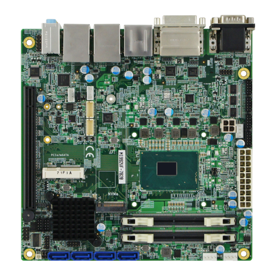
Page 16: Overview
Overview Top View *The photos above are for reference only. Some minor components may differ. MI992 User’s Manual... - Page 17 General Information I/O View Name Name COM1 Port Audio Line-In COM2 Port Audio Line-Out DVI-D Port Microphone-In USB 3.0 Ports DisplayPort LAN Ports HDMI Port MI992 User’s Manual...
-
Page 18: Dimensions
Dimensions MI992 User’s Manual... -
Page 19: Chapter 2 Hardware Configuration
Hardware Configuration This section provides information on jumper settings and connectors on the MI992 in order to set up a workable system. On top of that, you will also need to install crucial pieces such as the CPU and the memory before using the product. The topics covered are: •... -
Page 20: Essential Installations Before You Begin
Gently push the module in an upright position unitl the ejector tabs of the memory slot close to hold the module in place when the module touches the bottom of the slot. To remove the module, press the ejector tabs outwards with your fintertips to eject the module. MI992 User’s Manual... -
Page 21: Setting The Jumpers
Hardware Configuration Setting the Jumpers Set up and configure your MI992 by using jumpers for various settings and features according to your needs and applications. Contact your supplier if you have doubts about the best configuration for your use. 2.2.1... -
Page 22: Jumper & Connector Locations On Mi992
Jumper & Connector Locations on MI992 MI992 User’s Manual... -
Page 23: Jumpers Quick Reference
Hardware Configuration Jumpers Quick Reference Function Jumper Name Page LVDS Power Selection PCIe (x16) Bifurcation Selection J10, J11 ME Register Clearance CMOS Data Clearance Factory Use Only 2.4.1 LVDS Power Selection (J16) Function Pin closed Illustration 3.3V (default) MI992 User’s Manual... -
Page 24: Pcie (X16) Bifurcation Selection (J10 & J11)
PCIe (x16) Bifurcation Selection (J10 & J11) Function Pin closed Illustration J10: Open 1 x PCIe (x16) (default) J11: Open J10: Open 2 x PCIe (x8) J11: Close J10: Close 1 x PCIe (x8) 2 x PCIe (x4) J11: Close MI992 User’s Manual... -
Page 25: Me Register Clearance (J21)
Hardware Configuration 2.4.3 ME Register Clearance (J21) Function Pin closed Illustration Normal (default) Clear ME MI992 User’s Manual... -
Page 26: Cmos Data Clearance (J22)
2.4.4 CMOS Data Clearance (J22) Function Pin closed Illustration Normal (default) Clear CMOS MI992 User’s Manual... -
Page 27: Connectors Quick Reference
USB 3.0 Port DisplayPort CN6, CN8, CN9, CN11 SATA 3.0 Port CN6 & CN8 are available for MI992VF only.) GbE LAN & USB 3.0 Ports CN7, CN10 HD Audio Connector CN12 Factory Use Only J20, JP5, JP7 MI992 User’s Manual... -
Page 28: Com1 & Com2 Rs-232/422/485 Ports (Cn1)
DCD, Data carrier detect DSR, Data set ready RXD, Receive data RTS, Request to send TXD, Transmit data CTS, Clear to send DTR, Data terminal ready RI, Ring indicator Ground Assignment RS-232 RS-422 RS-485 DATA- DATA+ Ground Ground Ground MI992 User’s Manual... -
Page 29: Com3 ~ Com6 Rs-232 Ports (J1, J2, J3, J4)
Hardware Configuration 2.5.2 COM3 ~ COM6 RS-232 Ports (J1, J2, J3, J4) J4: COM3 J3: COM4 J2: COM5 J1: COM6 Assigment Assigment DCD# SIN# SOUT DSR# DTR# RTS# CTS# MI992 User’s Manual... -
Page 30: 20-Pin Atx Power Connector (J5)
2.5.3 20-pin ATX Power Connector (J5) Assigment Assigment 3.3V 3.3V 3.3V -12V Ground Ground PS-ON Ground Ground Ground Ground Ground Power good 5VSB +12V MI992 User’s Manual... -
Page 31: Digital I/O Connector (J6)
Hardware Configuration 2.5.4 Digital I/O Connector (J6) (4-In, 4-Out) Assigment Assigment Ground Out3 Out1 Out2 Out0 MI992 User’s Manual... -
Page 32: 4-Pin Atx 12V Power Connector (J7)
2.5.5 4-pin ATX 12V Power Connector (J7) Assigment Assigment Ground +12V Ground +12V 2.5.6 Battery Connector (J24) Assignment Battery+ Ground MI992 User’s Manual... -
Page 33: Front Panel Audio Connector (J23)
Hardware Configuration 2.5.7 Front Panel Audio Connector (J23) Assigment Assigment MIC IN_L Ground MIC IN_R LINE_R Ground Sense LINE_L Ground MI992 User’s Manual... -
Page 34: Front Panel Settings Connector (J25)
Orientation is not required when making a connection to this header. • Power LED (Pins 7 and 8) This connector connects to the system power LED on control panel. This LED will light when the system turns on. MI992 User’s Manual... -
Page 35: Lcd Backlight Connector (Jp2)
Hardware Configuration 2.5.9 LCD Backlight Connector (JP2) Assigment Assigment +12V Brightness Control Backlight Enable Ground MI992 User’s Manual... -
Page 36: Lvds Connector (Jp3, Jp4)
2.5.10 LVDS Connector (JP3, JP4) JP4: 1 channel JP3: 2 channel Assigment Assigment TX0+ TX0- Ground Ground TX1+ TX1- Ground 5V / 3.3V TX3+ TX3- TX2+ TX2- Ground Ground TXC+ TXC- ENABKL 5V/3.3V +12V +12V MI992 User’s Manual... -
Page 37: Usb 2.0 Connector (Jp6, Jp8)
Hardware Configuration 2.5.11 USB 2.0 Connector (JP6, JP8) Assigment Assigment Ground Ground MI992 User’s Manual... -
Page 38: Cpu Fan Power Connector (Cpu_Fan1)
2.5.12 CPU Fan Power Connector (CPU_FAN1) (PWM mode only) Assigment Assigment Ground Rotation detection +12V Control MI992 User’s Manual... -
Page 39: System Fan Power Connector (Sys_Fan1, Sys_Fan2)
Hardware Configuration 2.5.13 System Fan Power Connector (SYS_FAN1, SYS_FAN2) SYS_FAN1 SYS_FAN2 (PWM / DC mode) Assigment Assigment Ground Rotation detection +12V Control MI992 User’s Manual... - Page 40 This page is intentionally left blank. MI992 User’s Manual...
-
Page 41: Chapter 3 Drivers Installation
Chapter 3 Drivers Installation This chapter introduces installation of the following drivers: • ® Intel Chipset Software Installation Utility • HD Graphics Driver • HD Audio Driver • LAN Driver • ® Intel Management Engine Drivers Installation... -
Page 42: Introduction
INF files for Plug & Play function for Intel chipset components. Follow the instructions below to complete the installation. Insert the disk enclosed in the package with the board. Click Intel on the left pane and then Intel(R) Skylake/Kabylake Chipset Drivers on the right pane. MI992 User’s Manual... - Page 43 Accept the software license agreement and proceed with the installation process. On the Readme File Information screen, click Install for installation. The driver has been completely installed. You are suggested to restart the computer for changes to take effect. MI992 User’s Manual...
-
Page 44: Hd Graphics Driver Installation
HD Graphics Driver Installation Click Intel on the left pane and then Intel(R) Skylake/Kabylake Chipset Drivers on the right pane. Click Intel(R) HD Graphics Driver. MI992 User’s Manual... - Page 45 Accept the license agreement and click Next. On the Readme File Information screen, click Next until the installation starts. The driver has been completely installed. You are suggested to restart the computer for changes to take effect. MI992 User’s Manual...
-
Page 46: Hd Audio Driver Installation
Click Realtek High Definition Audio Driver. On the Welcome screen of the InstallShield Wizard, click Next. Click Next until the installation starts. The driver has been completely installed. You are suggested to restart the computer for changes to take effect. MI992 User’s Manual... -
Page 47: Lan Driver Installation
Driver Installation LAN Driver Installation Click Intel on the left pane and then Intel(R) Skylake/Kabylake Chipset Drivers on the right pane. Click Intel(R) PRO LAN Network Drivers.. MI992 User’s Manual... - Page 48 On the Setup Options screen, click the checkbox to select the desired driver(s) for installation. Then click Next to continue. The wizard is ready for installation. Click Install. As the installation is complete, you are suggested to restart the computer for changes to take effect. MI992 User’s Manual...
-
Page 49: Intel ® Management Engine Drivers Installation
Driver Installation ® Intel Management Engine Drivers Installation Click Intel on the left pane and then Intel(R) Skylake/Kabylake Chipset Drivers on the right pane. Click Intel(R) ME 11.x Drivers. MI992 User’s Manual... - Page 50 When the Welcome screen appears, click Next. Accept the license agreement and click Next until the installation starts. As the driver has been sccessfully installed, you are suggested to restart the computer for changes to take effect. MI992 User’s Manual...
-
Page 51: Chapter 4 Bios Setup
Chapter 4 BIOS Setup This chapter describes the different settings available in the AMI BIOS that comes with the board. The topics covered in this chapter are as follows: • Main Settings • Advanced Settings • Chipset Settings • Boot Settings •... -
Page 52: Introduction
These defaults have been carefully chosen by both AMI and your system manufacturer to provide the absolute maximum performance and reliability. Changing the defaults could make the system unstable and crash in some cases. MI992 User’s Manual... -
Page 53: 4.3 Main Settings
BIOS Setup 4.3 Main Settings BIOS Setting Description System Date Sets the date. Use the <Tab> key to switch between the data elements. System Time Set the time. Use the <Tab> key to switch between the data elements. MI992 User’s Manual... -
Page 54: 4.4 Advanced Settings
Shows super IO monitor hardware status. Hardware Monitor CSM Configuration Enables / Disables option ROM execution settings, etc. NVMe Configuration NVMe device option settings. USB Configuration Displays USB configuration parameters. Trusted Computing is available for MI992VF series only. MI992 User’s Manual... -
Page 55: Cpu Configuration
Disabled for other OS (OS not optimized for Hyper-Threading Technology). Enables / Disables AES (Advanced Encription Standard). Intel Trusted Enables / Disables utilization of additional Execution Technology hardware capabilities provided by Intel(R) Trusted Execution Technology. Changes require a full power cycle to take effect. MI992 User’s Manual... -
Page 56: Pch-Fw Configuration
When disabled AMT BIOS features are no longer supported and user is no longer able to access MEBx Setup. Note: This option does not disable Manageability features in FM. AMT BIOS Features is available for MI992VF series only. MI992 User’s Manual... -
Page 57: Trusted Computing
Note: PCH-FW Configuration is only available for MI992VF only. BIOS Setting Description Security Device Enables / Disables BIOS support for security Support device. OS will not show security device. TCG EFI protocol and INTIA interface will not be available. MI992 User’s Manual... -
Page 58: Acpi Settings
(OS/S4 Sleep State). This option may be not effective with some OS. ACPI Sleep State Selects an ACPI sleep state where the system will enter when the Suspend button is pressed. Options: Suspend Disabled, S3 (Suspend to RAM) MI992 User’s Manual... -
Page 59: Lvds (Edp/Dp) Configuration
BIOS Setup 4.4.5 LVDS (eDP/DP) Configuration BIOS Setting Description LVDS (eDP/DP) Enables / Disables LVDS (eDP/DP). Support MI992 User’s Manual... -
Page 60: Ismart Controller
For example, if setting up a schedule from Wednesday 5 p.m. to Thursday 2 a.m., configure two schedule slots. But if setting up a schedule from 3 p.m to 5 p.m. on Wednesday, configure only a schedule slot. MI992 User’s Manual... -
Page 61: Fintek Super Io Configuration
Disable the function to shutdown the standby power. Options: All Enable, Enable Ethernet for WOL, All Disable. Serial Port Sets parameters of Serial Ports. Configuration Enables / Disables the serial port and select an optimal setting for the Super IO device. MI992 User’s Manual... - Page 62 IO = 2E8h; IRQ = 3, 4, 5, 6, 7, 9, 10, 11, 12 Device Mode Select Changes the serial port mode to RS-232 / 422 / 485. Options: • RS232 • RS485 TX Low Active • RS485 with Termination TX Low Active • RS422 • RS422 with Termination MI992 User’s Manual...
- Page 63 IO = 2E8h; IRQ = 3, 4, 5, 6, 7, 9, 10, 11, 12 Device Mode Select Changes the serial port mode to RS-232 / 422 / 485. Options: • RS232 • RS485 TX Low Active • RS485 with Termination TX Low Active • RS422 • RS422 with Termination MI992 User’s Manual...
- Page 64 IO = 2E8h; IRQ = 3, 4, 5, 6, 7, 9, 10, 11, 12 • IO = 2F0h; IRQ = 3, 4, 5, 6, 7, 9, 10, 11, 12 • IO = 2E0h; IRQ = 3, 4, 5, 6, 7, 9, 10, 11, 12 MI992 User’s Manual...
- Page 65 IO = 2E8h; IRQ = 3, 4, 5, 6, 7, 9, 10, 11, 12 • IO = 2F0h; IRQ = 3, 4, 5, 6, 7, 9, 10, 11, 12 • IO = 2E0h; IRQ = 3, 4, 5, 6, 7, 9, 10, 11, 12 MI992 User’s Manual...
- Page 66 IO = 2E8h; IRQ = 3, 4, 5, 6, 7, 9, 10, 11, 12 • IO = 2F0h; IRQ = 3, 4, 5, 6, 7, 9, 10, 11, 12 • IO = 2E0h; IRQ = 3, 4, 5, 6, 7, 9, 10, 11, 12 MI992 User’s Manual...
- Page 67 IO = 2E8h; IRQ = 3, 4, 5, 6, 7, 9, 10, 11, 12 • IO = 2F0h; IRQ = 3, 4, 5, 6, 7, 9, 10, 11, 12 • IO = 2E0h; IRQ = 3, 4, 5, 6, 7, 9, 10, 11, 12 MI992 User’s Manual...
-
Page 68: Fintek Super Io Hardware Monitor
The values are read-only values as monitored by the system and show the PC health status. CPU Shutdown Options: Disabled / 70 °C / 75 °C / 80 °C / 85 °C / Temperature 90 °C / 95 °C MI992 User’s Manual... -
Page 69: Csm Configuration
Boot option filter Controls the priority of Legacy and UEFI ROMs. Options: UEFI and Legacy / Legacy only / UEFI only Network Controls the execution of UEFI and Legacy PXE OpROM. Options: Do not launch / Legacy MI992 User’s Manual... -
Page 70: Nvme Configuration
Controls the execution of UEFI and Legacy Video OpROM. Options: Do not lanuch / UEFI / Legacy Other PCI devices Determines OpROM execution policy for devices other than network, storage or video. Options: Do not lanuch / UEFI / Legacy 4.4.10 NVMe Configuration MI992 User’s Manual... -
Page 71: Usb Configuration
Options: 1 sec / 5 sec / 10 sec / 20 sec Device reset time-out Seconds of delaying execution of start unit command to USB mass storage device. Options: 10 sec / 20 sec / 30 sec / 40 sec MI992 User’s Manual... - Page 72 The maximum time the device will take before it delay properly reports itself to the Host Controller. Auto uses default value for a Root port it is 100ms. But for a Hub port, the delay is taken from Hub descriptor. Options: Auto / Manual MI992 User’s Manual...
-
Page 73: 4.5 Chipset Settings
BIOS Setup 4.5 Chipset Settings BIOS Setting Description System Agent (SA) System Agent (SA) parameters Configuration PCH-IO Configuration PCH parameters MI992 User’s Manual... -
Page 74: System Agent (Sa) Configuration
4.5.1 System Agent (SA) Configuration BIOS Setting Description Graphics Configures the graphics settings. Configuration VT-d Checks if VT-d function on MCH is supported. MI992 User’s Manual... - Page 75 Options: 0M / 32M / 64M / 4M / 8M / 12M / 16M / 20M / 24M / 28M / 32M/F7 / 36M / 40M / 44M / 48M / 52M / 56M / 60M MI992 User’s Manual...
- Page 76 BIOS Setting Description DVMT Total Gfx Mem Selects DVMT 5.0 total graphic memory size used by the internal graphcis device. Options: 256M / 128M / MAX MI992 User’s Manual...
-
Page 77: Pch-Io Configuration
4.5.2 PCH-IO Configuration BIOS Setting Description SATA and RST Configures SATA devices. Configuration PCH LAN Controller Enables / Disables the onboard NIC. Wake on LAN Enable Enables / Disables the integrated LAN to wake up the system. MI992 User’s Manual... - Page 78 Enables / Disables the SATA device. SATA Mode Selection Determines how SATA controller(s) operate. Options: AHCI / Intel RST Premium Serial ATA Ports Enables / Disables serial ports. SATA Ports Hot Plug Enables / Disables SATA Ports HotPlug. MI992 User’s Manual...
-
Page 79: 4.6 Security Settings
BIOS Setup 4.6 Security Settings BIOS Setting Description Administrator Sets an administrator password for the setup Password utility. User Password Sets a user password. MI992 User’s Manual... -
Page 80: 4.7 Boot Settings
Has no effect for BBS boot options. New Boot Option Controls the placement of newly detected UEFI Policy boot option. Boot mode select Selects a Boot mode, Legacy / UEFI. Boot Option Priorities Sets the system boot order. MI992 User’s Manual... -
Page 81: 4.8 Save & Exit Settings
Restore Defaults Restores / Loads defaults values for all the setup options. Save as User Defaults Saves the changes done so far as User Defaults. Restore User Defaults Restores the user defaults to all the setup options. MI992 User’s Manual... - Page 82 This page is intentionally left blank. MI992 User’s Manual...
-
Page 83: Appendix
Appendix This section provides the mapping addresses of peripheral devices, the sample code of watchdog timer configuration, and types of on-board connectors. -
Page 84: I/O Port Address Map
Motherboard resources 0x000000B2-0x000000B3 Motherboard resources 0x00000680-0x0000069F Motherboard resources 0x0000FFFF-0x0000FFFF Motherboard resources 0x0000FFFF-0x0000FFFF Motherboard resources 0x0000FFFF-0x0000FFFF Motherboard resources 0x00001800-0x000018FE Motherboard resources 0x0000164E-0x0000164F Motherboard resources 0x00000040-0x00000043 System timer 0x00000050-0x00000053 System timer 0x00000800-0x0000087F Motherboard resources 0x0000F000-0x0000F03F Intel(R) HD Graphics 630 MI992 User’s Manual... - Page 85 Programmable interrupt controller 0x00000030-0x00000031 Programmable interrupt controller 0x00000034-0x00000035 Programmable interrupt controller 0x00000038-0x00000039 Programmable interrupt controller 0x0000003C-0x0000003D Programmable interrupt controller 0x000000A0-0x000000A1 Programmable interrupt controller 0x000000A4-0x000000A5 Programmable interrupt controller 0x000000A8-0x000000A9 Programmable interrupt controller 0x000000AC-0x000000AD Programmable interrupt controller 0x000000B0-0x000000B1 Programmable interrupt controller MI992 User’s Manual...
- Page 86 Programmable interrupt controller 0x0000F0A0-0x0000F0A7 Intel(R) Active Management Technology - SOL (COM7) 0x00001854-0x00001857 Motherboard resources 0x0000FF00-0x0000FFFE Motherboard resources 0x0000F040-0x0000F05F Intel(R) 100 Series/C230 Series Chipset Family SMBus - A123 0x00000060-0x00000060 Standard PS/2 Keyboard 0x00000064-0x00000064 Standard PS/2 Keyboard 0x000000F0-0x000000F0 Numeric data processor MI992 User’s Manual...
-
Page 87: Interrupt Request Lines (Irq)
SOL (COM7) IRQ 54 ~ IRQ 204 Microsoft ACPI-Compliant System IRQ 256 ~ IRQ 511 Microsoft ACPI-Compliant System IRQ 4294967283 Intel(R) Management Engine Interface IRQ 4294967284 Intel(R) I211 Gigabit Network Connection IRQ 4294967285 Intel(R) I211 Gigabit Network Connection MI992 User’s Manual... - Page 88 Intel(R) I211 Gigabit Network Connection IRQ 4294967291 Intel(R) HD Graphics 630 IRQ 4294967292 Intel(R) Ethernet Connection (2) I219-LM IRQ 4294967293 Standard SATA AHCI Controller IRQ 4294967294 Intel(R) 100 Series/C230 Series Chipset Family PCI Express Root Port #3 - A112 MI992 User’s Manual...
-
Page 89: Watchdog Timer Configuration
**endptr; char SIO; printf("Fintek 81866 watch dog program\n"); SIO = Init_F81866(); if (SIO == 0) printf("Can not detect Fintek 81866, program abort.\n"); return(1); }//if (SIO == 0) if (argc != 2) printf(" Parameter incorrect!!\n"); return (1); MI992 User’s Manual... - Page 90 DisableWDT(void) unsigned char bBuf; Set_F81866_LD(0x07); //switch to logic device 7 bBuf = Get_F81866_Reg(0xFA); bBuf &= ~0x01; Set_F81866_Reg(0xFA, bBuf); //disable WDTO output bBuf = Get_F81866_Reg(0xF5); bBuf &= ~0x20; bBuf |= 0x40; Set_F81866_Reg(0xF5, bBuf); //disable WDT //--------------------------------------------------------------------------- //--------------------------------------------------------------------------- MI992 User’s Manual...
- Page 91 Init_Finish; F81866_BASE = 0x00; result = F81866_BASE; Init_Finish: return (result); //--------------------------------------------------------------------------- void Unlock_F81866 (void) outportb(F81866_INDEX_PORT, F81866_UNLOCK); outportb(F81866_INDEX_PORT, F81866_UNLOCK); //--------------------------------------------------------------------------- void Lock_F81866 (void) outportb(F81866_INDEX_PORT, F81866_LOCK); //--------------------------------------------------------------------------- void Set_F81866_LD( unsigned char LD) Unlock_F81866(); outportb(F81866_INDEX_PORT, F81866_REG_LD); outportb(F81866_DATA_PORT, LD); Lock_F81866(); MI992 User’s Manual...
- Page 92 #define F81866_DATA_PORT (F81866_BASE+1) //--------------------------------------------------------------------------- #define F81866_REG_LD 0x07 //--------------------------------------------------------------------------- #define F81866_UNLOCK 0x87 #define F81866_LOCK 0xAA //--------------------------------------------------------------------------- unsigned int Init_F81866(void); void Set_F81866_LD( unsigned char); void Set_F81866_Reg( unsigned char, unsigned char); unsigned char Get_F81866_Reg( unsigned char); //--------------------------------------------------------------------------- #endif // F81866_H MI992 User’s Manual...
-
Page 93: On-Board Connector Types
Appendix On-Board Connector Types Connector Function Type Name J1 (COM6), J2 (COM5), COM3 ~ COM6 RS-232 Ports HK_DF11-10S-PA66H J3 (COM4), J4 (COM3) LCD Backlight Connector E-CALL_0110-161-040 LVDS Connector JP3, JP4 HIROSE_DF20G-20DP-1V(56) USB 2.0 Connector JP6, JP8 HK_DF11-8S-PA66H MI992 User’s Manual...
Need help?
Do you have a question about the MI992 and is the answer not in the manual?
Questions and answers