
Subscribe to Our Youtube Channel
Related Manuals for IBASE Technology MI988


Summary of Contents for IBASE Technology MI988
- Page 1 MI988 AMD Ryzen™ Embedded V1000 Mini-ITX Motherboard User’s Manual Version 1.0 (July 2018)
- Page 2 No part of this publication may be reproduced, copied, stored in a retrieval system, translated into any language or transmitted in any form or by any means, electronic, mechanical, photocopying, or otherwise, without the prior written consent of IBASE Technology, Inc. (hereinafter referred to as “IBASE”). Disclaimer IBASE reserves the right to make changes and improvements to the products described in this document without prior notice.
-
Page 3: Compliance
0.1% by weight (1000 ppm) except for cadmium, limited to 0.01% by weight (100 ppm). • Lead (Pb) • Mercury (Hg) • Cadmium (Cd) • Hexavalent chromium (Cr6+) • Polybrominated biphenyls (PBB) • Polybrominated diphenyl ether (PBDE) MI988 User’s Manual... -
Page 4: Important Safety Information
CAUTION Replace only with the same or equivalent type recommended by the manufacturer. Dispose of used batteries according to the manufacturer’s instructions or recycle them at a local recycling facility or battery collection point. MI988 User’s Manual... -
Page 5: Warranty Policy
Software in use (such as OS and application software, including the version numbers) If repair service is required, you can download the RMA form at http://www.ibase.com.tw/english/Supports/RMAService/. Fill out the form and contact your distributor or sales representative. MI988 User’s Manual... -
Page 6: Table Of Contents
2.1.1 Installing the Memory ............12 Setting the Jumpers ................13 2.2.1 How to Set Jumpers ............. 13 Jumper & Connector Locations on MI988 .......... 14 Jumpers Quick Reference ..............15 2.4.1 LCD Panel Power Selection (JP2) ........15 2.4.2 LCD Backlight Level (JP3) ........... - Page 7 Network Stack Configuration ..........45 4.4.10 CSM Configuration ...............46 4.4.11 NVMe Configuration .............46 4.4.12 USB Configuration ..............47 Chipset Settings .................48 4.5.1 SB USB Configuration ............48 Security Settings ................49 Boot Settings ..................49 Save & Exit Settings ................50 Appendix ..................51 MI988 User’s Manual...
- Page 8 I/O Port Address Map ................ 52 Interrupt Request Lines (IRQ) ............55 Watchdog Timer Configuration ............58 Onboard Connector Types ..............63 MI988 User’s Manual viii...
-
Page 9: Chapter 1 General Information
Chapter 1 General Information The information provided in this chapter includes: • Features • Packing List • Specifications • Block Diagram • Board Overview • Board Dimensions... -
Page 10: Introduction
Introduction MI988 is a mini-ITX motherboard based on the AMD Ryzen™ V1000 APU. It offers high-definition visual experience and high performance on graphics processing. It can also be well utilized for designs of low power consumption in a board range of markets, including industrial control &... -
Page 11: Packing List
This User’s Manual Optional Accessories IBASE provides optional accessories as follows. Please contact us or your dealer if you need any. • Power Adaptor (150W) • COM Port Cable (PK1H) • USB Cable (USB2K-9) • Audio Cable (Audio-18K) MI988 User’s Manual... -
Page 12: Specifications
1 x DisplayPort 1.4 (3840 x 2160 at 60 Hz) Display • 1 x 24-bit dual channel LVDS (1920 x 1080 at 60 Hz) or eDP (1920 x 1080 at 60 Hz) 2 x RJ45 GbE LAN 4 x USB 3.1 MI988 User’s Manual... - Page 13 Operation: 0 ~ 60 °C (32 ~ 140 °F) • Temperature Storage: -20 ~ 80 °C (-4 ~ 176 °F) • Relative 0 ~ 90 %, non-condensing at 60 °C Humidity All specifications are subject to change without prior notice. MI988 User’s Manual...
-
Page 14: Block Diagram
Block Diagram MI988 User’s Manual... -
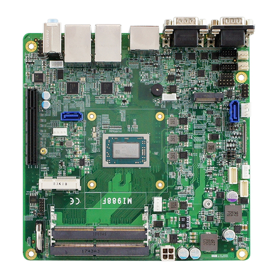
Page 15: Overview
General Information Overview Top View *The photos above are for reference only. Some minor components may differ. MI988 User’s Manual... - Page 16 I/O View Name Name COM3 Port Audio Line-In COM4 Port Audio Line-Out COM1 Port Microphone-In COM2 Port USB 3.1 Ports DisplayPort HDMI Port GbE LAN Ports MI988 User’s Manual...
-
Page 17: Dimensions
General Information Dimensions MI988 User’s Manual... - Page 18 This page is intentionally left blank. MI988 User’s Manual...
-
Page 19: Chapter 2 Hardware Configuration
Chapter 2 Hardware Configuration This section provides information on jumper settings and connectors on the board in order to set up a workable system. On top of that, you will also need to install crucial pieces such as the CPU and the memory before using the product. The topics covered are: •... -
Page 20: Installations
Gently push the module in an upright position until the clips of the slot close to hold the module in place when the module touches the bottom of the slot. To remove the module, press the clips outwards with both hands, and the module will pop-up. MI988 User’s Manual... -
Page 21: Setting The Jumpers
1 2 3 When two pins of a jumper are encased in a jumper cap, this jumper is closed, i.e. turned On. When a jumper cap is removed from two jumper pins, this jumper is open, i.e. turned Off. MI988 User’s Manual... -
Page 22: Jumper & Connector Locations On Mi988
Jumper & Connector Locations on MI988 MI988 User’s Manual... -
Page 23: Jumpers Quick Reference
Jumper Name Page LCD Panel Power Selection LCD Backlight Level PWM Backlight Control Level eDP Panel Power Selection eDP / LVDS Selection Clearing CMOS Data 2.4.1 LCD Panel Power Selection (JP2) Function Pin closed Illustration 3.3V (default) MI988 User’s Manual... -
Page 24: Lcd Backlight Level (Jp3)
2.4.2 LCD Backlight Level (JP3) Function Pin closed Illustration 3.3V (default) 2.4.3 PWM Backlight Control Level (JP4) Function Pin closed Illustration 3.3V (default) MI988 User’s Manual... -
Page 25: Edp Panel Power Selection (Jp5)
Hardware Configuration 2.4.4 eDP Panel Power Selection (JP5) Function Pin closed Illustration 3.3V (default) MI988 User’s Manual... -
Page 26: Edp / Lvds Selection (Jp6)
2.4.5 eDP / LVDS Selection (JP6) Function Pin closed Illustration Auto Detection (default) LVDS Only 2.4.6 Clearing CMOS Data (JP7) Function Pin closed Illustration Normal (default) Clear CMOS MI988 User’s Manual... -
Page 27: Connectors Quick Reference
CN2, CN4 Ports DisplayPort & HDMI Port DDR4 SO-DIMM Slot J2, J3 Mini-PCIe Slot M.2 M2280 Slot SATA III Connector SATA0, SATA1 PCIe (x8) Slot PCIE1 RTC Lithium Button Cell Holder BAT1 Factory Use Only J12, J15, J20 MI988 User’s Manual... -
Page 28: Edp Connector (Cn1)
+3.3V (default) / +5V Ground +3.3V (default) / +5V AUXP +3.3V (default) / +5V AUXN Ground Ground VCC3 Ground VCC12 Ground HOT PLUG Ground Ground VCC5 Brightness Ground BKLT_EN VCC12 VCC3 Ground Ground TXN1 SMB_CLK TXP1 SMB_DATA Ground MI988 User’s Manual... -
Page 29: Com3 & Com4 Rs-232 Ports (Cn6)
COM3 & COM4 RS-232 Ports (CN6) COM3: COM4: Signal Name Signal Name DCD, Data carrier detect DSR, Data set ready RXD, Receive data RTS, Request to send TXD, Transmit data CTS, Clear to send DTR, Data terminal RI, Ring indicator ready Ground MI988 User’s Manual... -
Page 30: Com1 & Com2 Rs-232/422/485 Ports (Cn7)
DCD, Data carrier detect DSR, Data set ready RXD, Receive data RTS, Request to send TXD, Transmit data CTS, Clear to send DTR, Data terminal RI, Ring indicator ready Ground Signal Name RS-232 RS-422 RS-485 Data- Data+ Ground Ground Ground MI988 User’s Manual... -
Page 31: Dc-In Power Connector (J1)
Hardware Configuration 2.5.4 DC-In Power Connector (J1) Signal Name Signal Name Ground Ground +12 ~ +24V +12 ~ +24V 2.5.5 LCD Backlight Connector (J8) Signal Name Signal Name +12V Brightness Control Backlight Enable Ground MI988 User’s Manual... -
Page 32: Lvds Connector (J6, J7)
LVDS Connector (J6, J7) J6 (Channel A) J7 (Channel B) Signal Name Signal Name TX0+ TX0- Ground Ground TX1+ TX1- Ground Ground TX2+ TX2- Ground Ground TXC+ TXC- Ground Ground TX3+ TX3- +3.3 / +5V +3.3 / +5V MI988 User’s Manual... -
Page 33: Sata Power Connector (J11, J21)
Hardware Configuration 2.5.7 SATA Power Connector (J11, J21) J21: Signal Name Signal Name Ground Ground +12V 2.5.8 Digital I/O Connector (J14) (4-In, 4-Out) Signal Name Signal Name Ground OUT3 OUT1 OUT2 OUT0 MI988 User’s Manual... -
Page 34: Front Panel Settings Connector (J13)
Orientation is not required when making a connection to this header. • Power LED (Pins 7 and 8) This connector connects to the system power LED on control panel. This LED will light when the system turns on. MI988 User’s Manual... -
Page 35: Com5 & Com6 Rs-232 Port (J18, J16)
RXD, Receive data TXD, Transmit data DTR, Data terminal ready Ground DSR, Data set ready RTS, Request to send CTS, Clear to send RI, Ring indicator 2.5.11 Speaker Connector (J17) Signal Name Signal Name Speaker-R+ Speaker-L- Speaker-R- Speaker-L+ MI988 User’s Manual... -
Page 36: Audio Connector (J19)
2.5.12 Audio Connector (J19) Signal Name Signal Name MIC IN_L Ground MIC IN_R AUD_DETECT LINE_IN_R JD_MIC_IN Sense LINE_IN_L JD_LINE_IN MI988 User’s Manual... -
Page 37: Fan Power Connectors
Fan Power Connectors (CPU_FAN1, SYS_FAN1, SYS_FAN2) CPU_FAN1: SYS_FAN2: SYS_FAN1: CPU_FAN1: CPU fan power connector Signal Name Signal Name Ground Rotation detection +12V Control SYS_FAN1 & SYS_FAN2: System fan power connectors Signal Name Signal Name Ground Rotation detection +12V MI988 User’s Manual... - Page 38 This page is intentionally left blank. MI988 User’s Manual...
-
Page 39: Chapter 3 Drivers Installation
Chapter 3 Drivers Installation This chapter introduces installation of the following drivers: • AMD Ryzen™ V1000 Graphics Driver • HD Audio Driver • LAN Driver... -
Page 40: Introduction
AMD Ryzen™ V1000 Graphics Drivers Insert the disk enclosed in the package with the board. Click AMD on the left pane and then AMD Ryzen V1000 Drivers on the right pane. Click AMD Ryzen V1000 Graphics Drivers. MI988 User’s Manual... - Page 41 Read the software license agreement and click Accept and Install to proceed. Choose and click on either Express Install or Custom Install. Click Install. The driver has been completely installed. Restart the computer for changes to take effect. MI988 User’s Manual...
-
Page 42: Hd Audio Driver Installation
Click Realtek High Definition Audio Driver. On the Welcome screen of the InstallShield Wizard, click Next. Click Next until the installation starts. The driver has been completely installed. Restart the computer for changes to take effect. MI988 User’s Manual... -
Page 43: Lan Driver Installation
Driver Installation LAN Driver Installation Click LAN Card on the left pane and then Intel LAN Controller Drivers on the right pane. Click Intel(R) I21x Gigabit Networks Drivers. When the Welcome screen appears, click Next. MI988 User’s Manual... - Page 44 On the Setup Options screen, tick the checkbox to select the desired driver(s) for installation. Then click Next to continue. The wizard is ready for installation. Click Install. As the installation is complete, restart the computer for changes to take effect. MI988 User’s Manual...
-
Page 45: Chapter 4 Bios Setup
Chapter 4 BIOS Setup This chapter describes the different settings available in the AMI BIOS that comes with the board. The topics covered in this chapter are as follows: • Main Settings • Advanced Settings • Chipset Settings • Boot Settings •... -
Page 46: Introduction
These defaults have been carefully chosen by both AMI and your system manufacturer to provide the absolute maximum performance and reliability. Changing the defaults could make the system unstable and crash in some cases. MI988 User’s Manual... -
Page 47: 4.3 Main Settings
Set the time. Use the <Tab> key to switch between the data elements. 4.4 Advanced Settings This section allows you to configure, improve your system and allows you to set up some system features according to your preference. MI988 User’s Manual... -
Page 48: Acpi Settings
OS. ACPI Sleep State Selects an ACPI sleep state where the system will enter when the Suspend button is pressed. 4.4.2 IDE Configuration BIOS Setting Description SATA Ports Detects the connection of SATA0 and SATA1. MI988 User’s Manual... -
Page 49: Edp/Lvds Configuration
Enables / Disables the eDP or LVDS function. 4.4.4 iSmart Controller BIOS Setting Description Power-On after Enables / Disables the system to be turned on Power failure automatically after a power failure. Temperature Generate the reset signal when system hands Guardian up on POST. MI988 User’s Manual... -
Page 50: Nct6116D Super Io Configuration
Power Control (EuP) Keep standby power: Enables all of the standby power and ignore Eup/ErP specification. Ethernet only: Only provides the standby power for the Ethernet chip. No standby power: Shut down all of the standby power. MI988 User’s Manual... - Page 51 Sets parameters of Serial Ports. Configuration Enables / Disables the serial port and select an optimal setting for the Super IO device. 4.4.5.1. Serial Port 1~6 Configuration BIOS Setting Description Serial Ports Enables / Disables the serial ports. MI988 User’s Manual...
-
Page 52: Hardware Monitor
The values are read-only values as monitored by the system and show the PC health status. CPU Shutdown Enables / Disables the CPU shutdown Temperature temperature function. 4.4.7 CPU Configuration BIOS Setting Description Node 0 Information Displays the memory information related to Node 0. MI988 User’s Manual... -
Page 53: Ami Graphic Output Protocol Policy
BIOS Setup 4.4.8 AMI Graphic Output Protocol Policy BIOS Setting Description Output Select Allows you to select an output interface. 4.4.9 Network Stack Configuration BIOS Setting Description Network Stack Enables / Disables UEFI Network Stack. MI988 User’s Manual... -
Page 54: Csm Configuration
4.4.10 CSM Configuration BIOS Setting Description CSM Support Enables / Disables CSM support. Network Controls the execution of UEFI and Legacy PXE OpROM. Options: Do not launch / Legacy 4.4.11 NVMe Configuration MI988 User’s Manual... -
Page 55: Usb Configuration
The maximum time the device will take before delay it properly reports itself to the Host Controller. Auto uses default value for a Root port it is 100ms. But for a Hub port, the delay is taken from Hub descriptor. Options: Auto / Manual MI988 User’s Manual... -
Page 56: 4.5 Chipset Settings
4.5 Chipset Settings 4.5.1 SB USB Configuration BIOS Setting Description SB USB Options for SB USB Configuration. Configuration 4.5.1.1. XHCI Ports BIOS Setting Description XHCI 0 & XHCI 1 Enables / Disables the XHCI0 & XHCI1 ports Ports (XHCI/EMCI). MI988 User’s Manual... -
Page 57: 4.6 Security Settings
65535(0xFFFF) means indefinite waiting. Bootup NumLock Selects the keyboard NumLock state. State Quiet Boot Enables / Disables Quiet Boot option. Boot mode select Selects a Boot mode, Legacy / UEFI. Boot Option Priorities Sets the system boot order. MI988 User’s Manual... -
Page 58: 4.8 Save & Exit Settings
Restore Defaults Restores / Loads defaults values for all the setup options. Save as User Saves the changes done so far as User Defaults Defaults. Restore User Restores the user defaults to all the setup Defaults options. MI988 User’s Manual... -
Page 59: Appendix
Appendix This section provides the mapping addresses of peripheral devices, the sample code of watchdog timer configuration, and types of on-board connectors. -
Page 60: I/O Port Address Map
PCI Express Root Complex 0x00000000-0x000003AF Direct memory access controller 0x000003E0-0x00000CF7 PCI Express Root Complex 0x000003B0-0x000003DF PCI Express Root Complex 0x00000D00-0x0000FFFF PCI Express Root Complex 0x0000F000-0x0000FFFF PCI Express Root Port 0x0000E000-0x0000EFFF PCI Express Root Port 0x00000040-0x00000043 System timer 0x00000010-0x0000001F Motherboard resources MI988 User’s Manual... - Page 61 Motherboard resources 0x00000C50-0x00000C51 Motherboard resources 0x00000C52-0x00000C52 Motherboard resources 0x00000C6C-0x00000C6C Motherboard resources 0x00000C6F-0x00000C6F Motherboard resources 0x00000CD0-0x00000CD1 Motherboard resources 0x00000CD2-0x00000CD3 Motherboard resources 0x00000CD4-0x00000CD5 Motherboard resources 0x00000CD6-0x00000CD7 Motherboard resources 0x00000CD8-0x00000CDF Motherboard resources 0x00000800-0x0000089F Motherboard resources 0x00000B00-0x00000B0F Motherboard resources 0x00000B20-0x00000B3F Motherboard resources MI988 User’s Manual...
- Page 62 Address Device Description 0x00000900-0x0000090F Motherboard resources 0x00000910-0x0000091F Motherboard resources 0x00000061-0x00000061 System speaker 0x00000081-0x00000083 Direct memory access controller 0x00000087-0x00000087 Direct memory access controller 0x00000089-0x0000008B Direct memory access controller 0x0000008F-0x0000008F Direct memory access controller 0x000000C0-0x000000DF Direct memory access controller MI988 User’s Manual...
-
Page 63: Interrupt Request Lines (Irq)
- 1.10 (Microsoft) IRQ 4 Communications Port (COM1) IRQ 3 Communications Port (COM2) IRQ 5 Communications Port (COM3) IRQ 5 Communications Port (COM4) IRQ 6 Communications Port (COM5) IRQ 6 Communications Port (COM6) IRQ 53 High Definition Audio Controller MI988 User’s Manual... - Page 64 AMD USB 3.10 eXtensible Host Controller - 1.10 (Microsoft) IRQ 4294967258 AMD USB 3.10 eXtensible Host Controller - 1.10 (Microsoft) IRQ 4294967257 AMD USB 3.10 eXtensible Host Controller - 1.10 (Microsoft) IRQ 4294967287 Intel(R) I211 Gigabit Network Connection MI988 User’s Manual...
- Page 65 Intel(R) I211 Gigabit Network Connection IRQ 4294967278 Intel(R) I211 Gigabit Network Connection IRQ 4294967277 Intel(R) I211 Gigabit Network Connection IRQ 4294967276 Intel(R) I211 Gigabit Network Connection IRQ 4294967289 AMD PSP 10.0 Device IRQ 4294967288 AMD PSP 10.0 Device MI988 User’s Manual...
-
Page 66: Watchdog Timer Configuration
(NCT6116D_BASE) #define NCT6116D_DATA_PORT (NCT6116D_BASE+1) //--------------------------------------------------------------------------- #define NCT6116D_REG_LD 0x07 //--------------------------------------------------------------------------- #define NCT6116D_UNLOCK 0x87 #define NCT6116D_LOCK 0xAA //--------------------------------------------------------------------------- unsigned int Init_NCT6116D(void); void Set_NCT6116D_LD( unsigned char); void Set_NCT6116D_Reg( unsigned char, unsigned char); unsigned char Get_NCT6116D_Reg( unsigned char); //--------------------------------------------------------------------------- #endif //__NCT6116D_H MI988 User’s Manual... - Page 67 (SIO == 0) printf("Can not detect Nuvoton NCT6116D, program abort.\n"); return(1); WDTInitial(); WDTEnable(10); WDTDisable(); return 0; //--------------------------------------------------------------------------- void WDTInitial(void) unsigned char bBuf; Set_NCT6116D_LD(0x08); //switch to logic device 8 bBuf = Get_NCT6116D_Reg(0x30); bBuf &= (~0x01); Set_NCT6116D_Reg(0x30, bBuf); //Enable WDTO //--------------------------------------------------------------------------- MI988 User’s Manual...
- Page 68 //enable timer bBuf = Get_NCT6116D_Reg(0xF0); bBuf &= (~0x08); Set_NCT6116D_Reg(0xF0, bBuf); //count mode is second Set_NCT6116D_Reg(0xF1, NewInterval); //set timer //--------------------------------------------------------------------------- void WDTDisable(void) Set_NCT6116D_LD(0x08); //switch to logic device 8 Set_NCT6116D_Reg(0xF1, 0x00); //clear watchdog timer Set_NCT6116D_Reg(0x30, 0x00); //watchdog disabled //--------------------------------------------------------------------------- MI988 User’s Manual...
- Page 69 //NCT6116D?? goto Init_Finish; NCT6116D_BASE = 0x2E; result = NCT6116D_BASE; ucDid = Get_NCT6116D_Reg(0x20); if (ucDid == 0xC4) //NCT6116D?? goto Init_Finish; NCT6116D_BASE = 0x00; result = NCT6116D_BASE; Init_Finish: return (result); //--------------------------------------------------------------------------- void Unlock_NCT6116D (void) outportb(NCT6116D_INDEX_PORT, NCT6116D_UNLOCK); outportb(NCT6116D_INDEX_PORT, NCT6116D_UNLOCK); //--------------------------------------------------------------------------- MI988 User’s Manual...
- Page 70 LD); Lock_NCT6116D(); //--------------------------------------------------------------------------- void Set_NCT6116D_Reg( unsigned char REG, unsigned char DATA) Unlock_NCT6116D(); outportb(NCT6116D_INDEX_PORT, REG); outportb(NCT6116D_DATA_PORT, DATA); Lock_NCT6116D(); //--------------------------------------------------------------------------- unsigned char Get_NCT6116D_Reg(unsigned char REG) unsigned char Result; Unlock_NCT6116D(); outportb(NCT6116D_INDEX_PORT, REG); Result = inportb(NCT6116D_DATA_PORT); Lock_NCT6116D(); return Result; //----------------------------------------------------------------------- MI988 User’s Manual...
-
Page 71: Onboard Connector Types
Hao Guo Xing Ye COM6 RS-232 J18, J16 DF11-10S-PA66H DF11-10DS-2C Port Speaker Connector B4B-PH-K-S PHR-4 E-Call Dupont Audio 0126-01-2821009 10P 2.54 mm-pitch Connector (female) TechBest Molex CPU_FAN1 W2-03I104132S1WT(A)-L 47054-1000 Fan Power Connectors SYS_FAN1, E-Call Molex SYS_FAN2 0110-02-111-030 22-01-2031 MI988 User’s Manual...
Need help?
Do you have a question about the MI988 and is the answer not in the manual?
Questions and answers