Sign In
Upload
Manuals
Brands
Servomex Manuals
Measuring Instruments
SERVOTOUGH LaserSPII mini
Servomex SERVOTOUGH LaserSPII mini Manuals
Manuals and User Guides for Servomex SERVOTOUGH LaserSPII mini. We have
1
Servomex SERVOTOUGH LaserSPII mini manual available for free PDF download: Operator's Manual
Servomex SERVOTOUGH LaserSPII mini Operator's Manual (162 pages)
Brand:
Servomex
| Category:
Measuring Instruments
| Size: 6 MB
Table of Contents
Table of Contents
4
Safety
10
General Warnings and Cautions
10
Laser Safety
11
Certification
11
Markings
13
Figure 1-1: 07931-Series Laser Transmitter Unit Rating Label Location
13
Figure 1-2: 07931-Series Laser Receiver Unit Certification Label Location
13
Figure 1-3: 07931-Series Laser Transmitter Unit Certification Label
14
Figure 1-4: 07931-Series Laser Receiver Unit Laser Label Location
14
Figure 1-5: 07931-Series Laser Transmitter Unit Laser Label Location
15
Figure 1-6: 07931-Series Laser Mount Laser Label Location
15
Introduction
16
Product Description
16
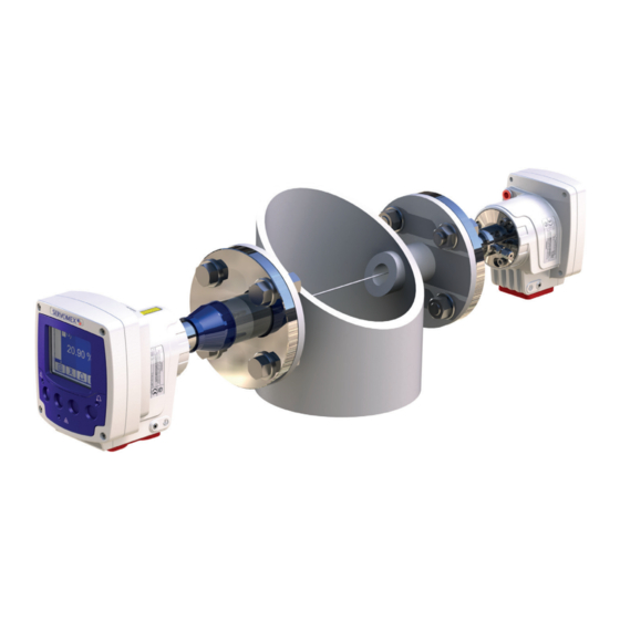
Figure 2-1: 07931-Series Laser Example Installation (Exploded View)
16
Figure 2-2: 07931-Series Laser Installation: Showing Insertion Tube, Thermal Spacer and Isolation Flange Options
17
Transmitter Unit
18
Figure 2-3: Transmitter Unit: Front, Rear, Side and Under-Side Views
18
Receiver Unit
20
Figure 2-4: Receiver Unit: Front, Rear, Side and Under-Side Views
20
Figure 2-5: Receiver Unit Indicators
21
Mounting Assembly (Flange and Window Purge)
22
Power Supply (Optional)
22
Product Specifications
22
Figure 2-6: Transmitter Unit Dimensions
22
Figure 2-7: Receiver Unit Dimensions
23
Additional Information
25
Materials in Contact with the Sample
26
Unpacking
27
Transmitter User Interface
28
Keypad
28
Transmitter Unit Indicator Leds
28
Figure 3-1: Transmitter Pushbutton Keys, Screen Icons and Indicator Leds
28
Start-Up Screen
29
Measurement Screen
29
Figure 3-2: Start up Screen
29
Figure 3-3: Example of a 'Live' Measurement Screen
29
Soft Key Legends
30
System and Measurement Status Icons
31
Navigation and Selecting On-Screen Options
32
Edit On-Screen Data
32
Figure 3-4: Example of a Typical Edit Screen
32
Password Protection
33
Configuration Setting Types
34
Menu Structure
42
Configuration
43
Configure Ma Inputs
43
Figure 4-1: Ma Input Sequential Menu
45
Process Environment Settings "Physical Set up
47
Figure 4-2: Physical Setup Sequential Menu
47
Figure 4-3: Purged Cross Stack Path Length Example
48
Figure 4-4: Non Purged Isolation Flange Cross Stack Path Length Example
48
Figure 4-5: Purge Compensation Segments
49
Figure 4-6: Purge Compensation Sequential Menu
50
User Settings
52
Figure 4-7: Network Settings Sequential Menu
52
Figure 4-8: Password Sequential Menu
53
Figure 4-9: Regional Settings Sequential Menu
55
Configure Ma Outputs
59
Figure 4-10: Ma Output Sequential Menu
60
Configure Relay Outputs
64
Filtering
67
Unit Select
67
X-Interference Offset
68
Clipping
68
Configure Measurement Alarms
70
Gain and Phase Settings
75
Figure 4-11: Raw Signal Graph Example
77
Figure 4-12: Filtered Graph Example
79
General Analyser Information
80
Status
80
Figure 5-1: Status Sequential Menu
80
Measurement
81
Data Log
82
Basic Data Log
82
Detailed Data Log
82
Log Run Mode
83
Log Intervals
83
Figure 6-1: Data Log Sequential Menu
83
Log Full
84
View Log
84
Clear Log
84
Log Media
85
Export
85
Figure 6-2: Micro SD Connector
86
Calibration
88
Save the Configuration Settings
88
Removing the Transmitter and Receiver Units from the Process
89
Connecting Transmitter and Receiver Units to the Calibration Cell
90
Figure 7-1: Offline Calibration View
90
Calibration
92
Figure 7-2: Physical Setup Sequential Menu
92
In Situ Validation (In-Line Span or Zero Check)
97
Installation
99
Installation Preparations
99
Figure 8-2: 07931-Series Laser Installation Distances
101
Figure 8-3: 07931-Series Laser Flange Dimensions
102
Figure 8-4: Process Flange Bolt Arrangement (4 Bolt Pattern)
104
Figure 8-5: Process Flange Positioning Tolerance
105
Figure 8-6 Flange Alignment Adaptor
106
Figure 8-8: Transmitter Unit Mounting Arrangement (Example Shown with Adjustable Mount)
110
Installation Overview
111
Figure 8-9: Receiver Unit Mounting Arrangement (Example Shown with Fixed Mount)
111
Figure 8-10: Installation Overview
113
Figure 8-11: 07931-Series Laser In-Situ Installation
114
Process Connections
115
Figure 8-12: Example of Mounting / Alignment Assembly Fitting Exploded View
116
Figure 8-13: Align M6 Screws with the Flange Joint
119
Figure 8-14: Rotate the Enclosure
119
Figure 8-15: Tighten the M6 Screws
120
Electrical Connections
121
Figure 8-16: Cable Screen Terminations
122
Figure 8-17: Cable Strip Lengths
123
Figure 8-18: Receiver Unit Cable Gland Position
123
Functional Earth / Ground Requirements
124
Figure 8-19: Transmitter Unit Cable Gland Positions
124
Figure 8-20: Opening the Transmitter Unit
126
Figure 8-21: 7-Way Main Terminal and Entry Glands
127
Figure 8-22: 8-Way Transmitter to Receiver Connector
128
Figure 8-23: Ethernet Connections
130
Figure 8-24: 12-Way Options Board Connections
131
Purge Connections
132
Figure 8-25: Transmitter Purge
133
Figure 8-26: Receiver Purge
134
Commissioning
136
Figure 8-27: Peel Back the Boot
138
Figure 8-28: Installation: Ball-Joint Adjustment Screws
139
Figure 8-29: Installation: Adjust Laser Intensity on the Photodiode
140
Service
142
Service Functions
142
Routine Maintenance
145
Cleaning
146
Routine Checks
146
Figure 9-1: Optical Windows
146
Alignment / Purging Flanges
147
Enclosure Purge and Breather (if Fitted)
147
User Replaceable Spare Parts
147
Certification Information
148
Hazardous Area Approval and Certification
148
Label Information
149
Figure 10-1: ATEX / Iecex Labels
149
Emc
150
Figure 10-2: SGS North American Label
150
Figure 10-3: General Purpose Label
150
Figure 10-4: Rating Label
150
Electrical Safety
151
Product Disposal
151
EU REACH Regulations
151
Index
153
Appendix Display Unit Conversion Factors
155
Appendix Modbus Setup
156
Implementation Guide for Modbus Communications
156
Advertisement
Advertisement
Related Products
Servomex SERVOTOUGH Oxy
Servomex SERVOTOUGH SpectraExact 2500 Series
Servomex SERVOFLEX MiniFood Pack
Servomex SERVOPRO Plasma
Servomex SERVOPRO FID
Servomex SERVOPRO MultiExact
Servomex SERVOFLEX MiniMP
Servomex SERVOTOUGH Laser SP 2930
Servomex SERVOPRO Chroma
Servomex 01440002D
Servomex Categories
Measuring Instruments
Analytical Instruments
Transmitter
Industrial Equipment
More Servomex Manuals
Login
Sign In
OR
Sign in with Facebook
Sign in with Google
Upload manual
Upload from disk
Upload from URL