Sign In
Upload
Manuals
Brands
Servomex Manuals
Analytical Instruments
SERVOPRO Chroma
Servomex SERVOPRO Chroma Manuals
Manuals and User Guides for Servomex SERVOPRO Chroma. We have
2
Servomex SERVOPRO Chroma manuals available for free PDF download: User Manual, Quick Start Manual
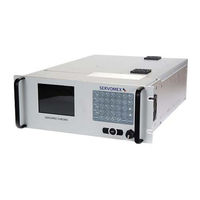
Servomex SERVOPRO Chroma User Manual (125 pages)
Trace Gas Analyser
Brand:
Servomex
| Category:
Measuring Instruments
| Size: 1 MB
Table of Contents
Table of Contents
3
Description and Definitions
9
Scope of this Manual
9
Safety Information
9
Description
10
Servopro Chroma Complete Rear Connector
10
Figure 1 : Servopro Chroma Complete Rear Connection
10
Servopro Chroma Reduced Rear Connector
11
Figure 2 : Servopro Chroma Reduced Rear Connection
11
FID Modification
12
Auxiliary Oven Rear Connecton
12
Figure 3 : FID Modification
12
Figure 4 : Auxiliary Oven Rear Connection
12
Standalone PC Rear Connecton
13
Figure 5 : Standalone PC Rear Connection
13
Software License
15
Microsoft Software License Term for Windows XP Embedded
15
Specifications
20
General
21
Gas
22
Table 1 : General Specification
22
Table 2 : Gas Specification
22
Oven Specification
23
Environmental Limits
23
Digital Relay Outputs
23
Table 3 : Oven Specification
23
Table 4 : Environmental Limits
23
Table 5 : Digital Relay Outputs
23
Ma Outputs
24
Digital Inputs
24
Hydrogen Relay Output
24
Table 6 : 4-20 Ma Outputs
24
Table 7 : Digital Inputs
24
Ethernet Port
25
Port
25
USB Connector
25
Table 8 : Hydrogen Relay Output
25
Table 9 : Ethernet Cable
25
Table 10 : RS-232 Port
25
Table 11 : RS-485 Port
25
Table 12 : RS-485 Port
25
Mains Input Cables (Master/Slave/Stand Alone PC)
26
Standard Features
26
Table 13 : Mains Cable
26
System Description
27
Introduction
27
Plasma Cell
28
Electric and Electronic Hardware Description
30
Signal Conditioning
30
Main PC and Graphic Display
30
Oven Heater and Control
30
I/O Board
31
Unpack the Servopro Chroma
32
Servopro Chroma User Interface
33
User Interface Control Description
33
Edit Box Control
33
Radio Control
33
Figure 6: Edit Box Control
33
Figure 7 : Radio Control
33
Slide Control
34
Push Button Control
34
Figure 8 : Slide Control
34
Figure 9 : Button Control
34
Grid Control
35
Combo Control
35
Figure 10 : Grid Control
35
Figure 11 : Combo Box Control
35
Check Box Control
36
Tab Control
36
Figure 12 : Check Box Control
36
Figure 13 : Check Box Control
36
Menu Description
37
Run
37
Real Time Chromatogram
37
Figure 14 : Menu Description
37
Figure 15 : Real Time Menu
38
Historic Values Menu
41
Table 14 : Run Time Menu
41
Alarm Historic Menu
42
Diagnostic
45
Figure 16 : Diagnostic Menu
45
Table 15 : Diagnostic Menu
47
Table 16 : Diagnostic Menu 2
47
Analyse Chromatogram
48
Figure 17 : Analyse Chromatogram
48
Table 17 : Configuration Menu
50
Trending
51
Figure 18 : Trending Menu
51
Figure 19 : Trending Menu Valve State
52
Table 18 : Trending Menu
53
Advanced Diagnostic
54
Figure 20 : Advanced Diagnostic Menu
54
Configuration
56
System
56
Figure 21 : System Menu
56
Table 19 : Unregulated Flow
58
Table 20 : Oven Set Point
58
Pid
60
Flow
60
Figure 22 : PID Menu
60
Figure 23 : Unregulated Flow Configuration Menu
61
Table 21 : Flow Factor
62
Figure 24 : Regulated Flow Configuration Menu
62
Cycle
64
Figure 25 : General Cycle Menu
64
Figure 26 : Peak Configuration Menu
65
Table 22 : Peak Configuration Columns
66
Table 23 : Peak Configuration Menu
66
Figure 27 : Peak Detection Configuration Menu
67
Figure 28 : Valve Configuration Menu
68
Figure 29 : Typical Sequence for Valve Timing
68
Figure 30 : Flow Timing Configuration Menu
69
Date and Time
70
Figure 31 : Date and Time Menu
70
Advanced Configuration
71
Figure 32 : Advanced Configuration Menu
71
Figure 33 : Detector Configuration Menu
73
Figure 34 : Advanced Flow Configuration Menu
74
Figure 35 : Advanced Valve Configuration Menu
75
Figure 36 : Advanced Oven Configuration Menu
76
Alarm
77
Figure 37 : Alarm Outputs Configuration Menu
77
Printers
78
Figure 38 : Printers Configuration Menu
78
Calibration
79
Figure 39 : Calibration Menu
79
Figure 40 : Span Calibration Menu
80
Calibration of the 4-20Ma Outputs
82
Figure 41 : 4-20 Ma Outputs Calibration Menu
82
Remote
84
Report Software
84
Figure 42 : Remote Software Menu
84
Remote Control
85
Figure 43 : Remote Control Menu
85
About
86
Figure 44 : about Menu
86
Chromatogram Saving
87
Figure 45 : Chromatogram Saving Menu
87
Quit
88
Installation and Setup
89
System Power up
89
Electrical Installation
89
Electrical Safety
89
Master Chassis Connection
91
Figure 46 - Master Chassis Electrical Connections
91
Slave Chassis Connection
92
Figure 47 - Master and Slave Chassis Electrical Connections
92
Stand Alone PC with Slave Chassis
93
Figure 48 - External PC Connections
93
Connecting Servopro Chroma Rear Connector
94
Digital Input
94
Figure 44- Digital Input Connection
94
Digital Output Contacts
95
Table 24 : Digital Output Contacts
95
Figure 45 - Digital Outputs Connection
95
Ma Outputs
96
Table 25 : 4-20 Ma Connections and Associated Fuses
96
Figure 46- 4-20 Ma Schematic and External Connections
96
FID Fuel Shut-Off Relay/Hydrogen Relay Output
97
Figure 47 - Connecting a Fuel Shut-Off Valve
97
Port
98
Auxiliary Oven Port
98
Gas Installation
99
Introduction
100
Carrier Gas Hardware Selection
101
Connecting the Servopro Chroma
102
General Operation
103
Routine Maintenance
103
Storage and Disposal
104
Storage
104
Disposal
104
Compliance
105
FID Addendum
106
Introduction
106
Overview
106
Logarithm Based Amplifier
106
Menus
107
Configuration-Advance Menu
107
Figure 48: Advanced Menu
107
Configuration-Advance Fid Menu
108
Table 26 : Advanced FID Menu Parameters
108
Figure 49: Advanced FID Menu
108
Configuration-Advance Detector Menu
110
Figure 50: Advanced Detector Menu
110
Configuration-Advance Flow Menu
111
Figure 51: Advanced Flow Menu
111
Configuration-Advance Oven Menu
112
Figure 52: Advanced Oven Menu
112
Monitoring and Configuration Menus
113
Figure 53: Monitoring Fig 1
113
Figure 54: Monitoring Fig 2
113
Figure 55: Monitoring Fig 3
114
Figure 56: Monitoring Fig 4
114
Figure 57: Monitoring
115
Diagnostic-Diagnostic Menu
116
Figure 58 : Diagnostic Menu
116
Configuration-Cycle Menu
117
Figure 59: Cycle Menu
117
Startup
118
Table 27 : Gas Flow Set Point
118
Table 28 : Gas Flow Set Point 2
118
Table 29 : Gas Ignition Point
118
System Errors
119
Troubleshooting
121
Table 30 : Troubleshooting
121
Addendum
122
Start Analysis
122
Analyser Status
122
Table 31 : RS-232 Start Analysis
122
Table 32 : RS-232 Analyser Status
122
Send Results
123
Table 33 : RS-232 Send Results
123
Enable-Disable Calibration
124
Respan
124
Table 34 : RS-232 Enable-Disable Calibration
124
Table 35 : RS-232 Respan
124
Product Disposal in Accordance with the Waste Electrical and Electronic Equipment (WEEE) Directive
125
REACH Regulation
125
Figure 60 :The WEEE Label
125
Advertisement
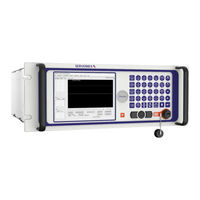
Servomex SERVOPRO Chroma Quick Start Manual (50 pages)
Brand:
Servomex
| Category:
Analytical Instruments
| Size: 1 MB
Table of Contents
Table of Contents
3
Description and Definitions
7
Scope of this Manual
7
Description of Analyser Rear Connections
8
SERVOPRO GC Complete Rear Connector
8
Figure 1 : SERVOPRO GC Complete Rear Connections
8
SERVOPRO GC Reduced Rear Connections
9
Figure 2 : SERVOPRO GC Reduced Rear Connections
9
Auxiliary Oven
10
Description of Auxiliary Oven
10
Auxiliary Oven Rear Connections
10
Figure 3 : Auxiliary Oven Rear Connections
10
Standalone PC Rear Connections
11
User Interface Menu Structure
11
Figure 4 : Standalone PC Rear Connections
11
Figure 5 : Menu Structure
11
Run Menu
12
Real Time Chromatogram Menu
12
Figure 6 : Run - Real Time Menu
12
Start Button (F2)
13
Injection Mode
13
Injection Status
13
Enhanced View (Ultra Only)
13
Figure 7 : Chromatogram in Enhanced View
13
Historic Values (F3)
14
Historic Alarm (F4)
15
Range (F5)
15
Figure 8 : Historic Values
15
Save (F6)
16
Undo Zoom (F8)
17
Print (Alt F2)
17
Remote Countdown
17
Historic Menu
17
Alarm Menu
17
Date & Time
20
Analyser Calibration
20
Figure 9 : Date & Time Menu
20
Noise Threshold (THRSH) Calibration
21
Figure 10 : Calibration-Calibration Menu
21
Span Calibration
22
Figure 11 : Calibration-Span Menu
24
Calibration of the 4-20Ma Outputs
25
Figure 12 : Calibration-4-20 Ma Outputs Menu
25
Remote
27
Report Software
27
Figure 13 : Remote Software Menu
27
About
28
Figure 14 : about Menu
28
Chromatogram Saving
29
Figure 15 : Historic-Chromatogram Saving Menu
29
Quit
30
Unpack the Analyser
31
Installation and Setup
32
Electrical Installation
32
Electrical Safety
32
Master Chassis Electrical Connections
32
Figure 16 : Master Chassis Electrical Connections
32
Master Chassis with Secondary Chassis Electrical Connections
33
Figure 17 : Master with Secondary Chassis, Electrical Connections
33
Figure 18 : Master with 2 Secondary Chassis, Electrical Connections
34
Stand-Alone PC with Secondary Chassis Electrical Connections
35
Figure 19 : Stand-Alone PC with Secondary, Electrical Connections
35
Figure 20 : Stand-Alone PC with Two Secondarys, Electrical Connections
36
Master/Secondary Chassis Rear Panel Electrical Connections
37
Digital Input
37
04400003A_0
37
Digital Output Contacts
37
Figure 21 : Digital Input Connection
37
Ma Outputs
38
Figure 22 : Digital Outputs Connection
38
RS-485 Port
39
Figure 23 : 4-20 Ma Schematic and External Connections
39
RS-232 Port
40
Auxiliary Oven Port
40
Gas Installation
41
Choosing the Right Materials for the Sampling System
41
Carrier Gas Hardware Selection
42
Gas Connections - Rear Panel
43
Master and Secondary Chassis
43
Auxiliary Oven
44
Internal Dilution System Setup (Nanochrome and Ultra Only)
44
Figure 24 : Internal Dilution System Schematic
44
Start-Up and Shutdown Procedure
46
Equipment/Tools
46
Installation Requirements
46
Start-Up Procedure
46
Shut-Down Procedure
48
Routine Maintenance
49
Storage and Disposal
50
Storage
50
Disposal
50
Advertisement
Related Products
Servomex SERVOPRO Plasma
Servomex SERVOPRO FID
Servomex SERVOPRO MultiExact
Servomex SERVOFLEX MiniFood Pack
Servomex SERVOTOUGH Laser SP 2930
Servomex SERVOFLEX MiniMP
Servomex SERVOTOUGH Oxy
Servomex SERVOTOUGH LaserSPII mini
Servomex SERVOTOUGH SpectraExact 2500 Series
Servomex 00700 001B
Servomex Categories
Measuring Instruments
Analytical Instruments
Transmitter
Industrial Equipment
More Servomex Manuals
Login
Sign In
OR
Sign in with Facebook
Sign in with Google
Upload manual
Upload from disk
Upload from URL