
Subscribe to Our Youtube Channel
Related Manuals for PIETRO FIORENTINI CIRVAL


Summary of Contents for PIETRO FIORENTINI CIRVAL
- Page 1 Cirval Medium-low pressure gas regulator Review A - Edition 09/2022 OPERATION, MAINTENANCE AND WARNING MANUAL...
- Page 2 MEDIUM PRESSURE REGULATOR INTRODUCTION | REV Operation, maintenance and warning manual...
-
Page 3: Introduction
Training of the personnel responsible for the equipment both in its use, as well as in its maintenance and application of the safety directions and procedures given in this manual is of particular importance. Revision: A COPYRIGHT 2022 © PIETRO FIORENTINI S.P.A. MEDIUM PRESSURE REGULATOR INTRODUCTION REV. A... - Page 4 MEDIUM PRESSURE REGULATOR INTRODUCTION | REV Operation, maintenance and warning manual...
-
Page 5: Revision History
1.1 - REVISION HISTORY Revision Date Review Contents index 09/2022 First issue Tab. 1.1. MEDIUM PRESSURE REGULATOR INTRODUCTION REV. A Operation, maintenance and warning manual... -
Page 6: Table Of Contents
INDEX 1 - INTRODUCTION ........................3 1.1 - REVISION HISTORY ..........................5 2 - GENERAL INFORMATION ....................11 2.1 - MANUFACTURER IDENTIFICATION ......................11 2.2 - PRODUCT IDENTIFICATION ........................11 2.3 - REGULATORY SYSTEM ......................... 11 2.4 - WARRANTY ............................11 2.5 - SYMBOLS USED IN THE MANUAL ...................... - Page 7 5.1.1 - PACKAGING AND FASTENING SYSTEMS USED FOR TRANSPORT ............46 5.2 - PHYSICAL CHARACTERISTICS OF THE EQUIPMENT ................48 5.2.1 - CIRVAL ..............................48 5.2.2 - CIRVAL + IFM ............................49 5.2.3 - CIRVAL + IMD ............................50 5.2.4 - CIRVAL + LA ............................51 5.3 - METHOD FOR ANCHORING AND LIFTING THE EQUIPMENT ..............
- Page 8 8.7 - COMMISSIONING PROCEDURE OF THE REGULATOR + BUILT-IN IFM MONITOR ....... 78 8.8 - COMMISSIONING PROCEDURE OF THE REGULATOR + IMD BUILT-IN MONITOR ......80 8.9 - COMMISSIONING PROCEDURE OF THE CIRVAL REGULATOR + SLAM-SHUT VALVE LA ....82 8.9.1 - CHECK FOR LEAKAGE OF THE LA SLAM-SHUT VALVE ..............82 8.9.2 - COMMISSIONING OF CIRVAL REGULATOR + LA SLAM-SHUT VALVE ..........84...
- Page 9 9.4.7 - LA SLAM-SHUT VALVE ........................126 9.4.8 - BALANCING BLOCK FOR CIRVAL 200 REGULATOR .................132 9.4.9 - BALANCING BLOCK FOR IFM BUILT-IN MONITOR FOR CIRVAL 200 MP AND TR......134 9.4.10 - BALANCING BLOCK FOR IMD BUILT-IN MONITOR FOR CIRVAL 200 BP ..........136 10 - FAULT FINDING AND TROUBLESHOOTING ..............
- Page 10 12.1 - GENERAL WARNINGS ......................... 160 12.2 - HOW TO REQUEST REPLACEMENT PARTS ..................160 13 - CALIBRATION TABLES ....................162 13.1 - CALIBRATION TABLE CIRVAL 200 ....................... 162 13.2 - CALIBRATION TABLE CIRVAL 300 ....................... 163 MEDIUM PRESSURE REGULATOR...
-
Page 11: General Information
PIETRO FIORENTINI S.P.A. guarantees that the equipment has been made with the best materials, with fine workmanship and complies with the quality requirements, specifications and performance envisaged in the order. The warranty will be considered null and void and PIETRO FIORENTINI S.P.A. will not be responsible for any damage and/ or malfunctions: •... -
Page 12: Symbols Used In The Manual
2.5 - SYMBOLS USED IN THE MANUAL Symbol Definition Symbol used to identify important warnings for operator and/or equipment safety. Symbol used to identify particularly important information in the manual. The information may also concern the safety of personnel involved in using the equipment. Obligation to consult the instruction manual/booklet. -
Page 13: Recipients, Supply And Conservation Of The Manual
Keep the manual near the equipment, in an accessible place known to all qualified technicians involved in its use and management. PIETRO FIORENTINI S.p.A. declines all responsibility for any damage to people, animals and things caused by failure to observe the warnings and operating methods described in this manual. -
Page 14: Identification Plates Applied
It is absolutely forbidden to remove the identification plates and/or replace them with others. If, for accidental reasons, the plates are damaged or removed, the customer must inform PIETRO FIORENTINI S.p.A. The appliance and its accessories are equipped with identification plates. -
Page 15: Identification Plates Glossary
2.8.1 - IDENTIFICATION PLATES GLOSSARY Table 2.6 describes the terms and abbreviations used on the identification plates: Term Description Accuracy class. Pressure increase slam-shut valve accuracy class. AG max “OPSO” (Over pressure shut off). Pressure decrease slam-shut valve accuracy class. AG min ”UPSO”(Under pressure shut off). -
Page 16: Measurement Unit Glossary
Term Description Complete set point range for tripping caused by pressure drop of the pressure switch incorpo- rated in the slam-shut valve. This field can be obtained by adjusting and/or replacing the components (for example spring or sensing element). Complete set point range for tripping caused by pressure drop of the pressure switch incorpo- Wdsu rated in the slam-shut valve. -
Page 17: Qualified Professionals
2.10 - QUALIFIED PROFESSIONALS Qualified operators in charge of using and managing the equipment in all its phases of technical life: Professional Definition Qualified technician able to: • carry out preventive/corrective maintenance activities on all mechanical parts of the Mechanical mainte- equipment subject to maintenance or repair;... - Page 18 MEDIUM PRESSURE REGULATOR GENERAL INFORMATION REV. A Operation, maintenance and warning manual...
-
Page 19: Safety
3 - SAFETY 3.1 - GENERAL SAFETY WARNINGS The equipment described in this manual is: • a device subject to pressure in pressurized systems; • normally included in systems transporting flammable gases (for example: natural gas). If the gas used is a combustible gas, the area where the equipment is installed is called a "danger zone" because there are residual risks of the formation of potentially explosive atmospheres. -
Page 20: Personal Protective Equipment
3.2 - PERSONAL PROTECTIVE EQUIPMENT In Table 3.9, Personal Protective Equipment (PPE) and its description are shown. An obligation is attached to each symbol. Personal protective equipment means any equipment intended to be worn by the worker for the purpose of protecting him against one or more hazards likely to threaten his safety or health while at work. -
Page 21: Residual Risks
3.3 - RESIDUAL RISKS The risks associated with the equipment and the principles adopted for their prevention are evaluated below, according to the following classification: (a) Elimination and/or reduction of risk. (b) Application of appropriate protective measures. (c) Information to users about residual risks. MEDIUM PRESSURE REGULATOR SAFETY REV. -
Page 22: Table Of Residual Risks Due To Pressure
3.3.1 - TABLE OF RESIDUAL RISKS DUE TO PRESSURE Effect and Risk and hazard Event and cause Solution and prevention consequence a. Handling and installation by appropriate Pressurized gas • Violent impact; means to avoid localized stresses. outlet. • Deformation; •... - Page 23 Effect and Risk and hazard Event and cause Solution and prevention consequence a. The user shall perform any maintenance Pressurized gas • Maintenance of the • Inappropriate open- with the equipment not in operation. leakage. device with the sys- ing of pressurized b.
-
Page 24: Residual Risks Table For Potentially Explosive Atmospheres
3.3.2 - RESIDUAL RISKS TABLE FOR POTENTIALLY EXPLOSIVE ATMOSPHERES Table 3.11 shows the conditions that can lead to the generation of potentially explosive atmosphere by respectively: • the pressure regulator CIRVAL; • the incorporated IFM monitor; • the incorporated IMD monitor;... - Page 25 Potentially ex- Operating condi- plosive atmo- Management measures tions sphere Normative references included in the operating and warning instructions Breakage of other This type of malfunction is not rea- non-metallic parts sonably expected since it involves static (outward) seals. (malfunction) •...
-
Page 26: Obligations And Prohibitions
3.4 - OBLIGATIONS AND PROHIBITIONS The list of obligations and prohibitions to be observed for operator safety is given below. It is mandatory to: • carefully read and understand the operating and warning instructions; • verify that the downstream equipment is properly sized according to the performance required of the regulator under the actual operating condition;... -
Page 27: Safety Pictograms
For the generated noise value of the equipment and further information, please contact PIETRO FIORENTINI S.p.A. The requirement to use ear muffs or earplugs to protect the operator's hearing remains in case the noise in the equipment installation environment (depending on specific operating conditions) exceeds 85 dBA. - Page 28 MEDIUM PRESSURE REGULATOR SAFETY | REV. A Operation, maintenance and warning manual...
-
Page 29: Description And Operation
4 - DESCRIPTION AND OPERATION 4.1 - GENERAL DESCRIPTION The CIRVAL equipment is a controlled pressure regulator for medium and low pressure that reduces the pressure of the incoming gas while keeping its downstream value stable even when the following change: •... -
Page 30: Regulator Reaction Modes
4.1.1 - REGULATOR REACTION MODES The CIRVAL equipment is a direct-acting regulator with a "fail open" reaction, i.e. it opens in case of: • rupture of the main diaphragm • lack of downstream pressure signal. 4.2 - OPERATION pstream pressUre ownstream pressUre Fig. - Page 31 In the absence of pressure, the plug (1) is kept in the open position by the thrust of the spring (4), via the lever mechanism (3) connected to the stem (2). The regulation of the downstream pressure (Pd) takes place through the comparison between: •...
-
Page 32: Intended Use
"Intended use". Any other use of the equipment than that envisaged must be authorized in advance in writing by PIETRO FIORENTINI S.p.A. In the absence of written permission, the use is considered improper. -
Page 33: Technical Characteristics/Performance
4.4 - TECHNICAL CHARACTERISTICS/PERFORMANCE The CIRVAL equipment is a regulator for medium and low pressure. The control system is balanced and guarantees a stable outlet pressure even when the inlet pressure varies. The main specifications of this regulator are: Technical features... -
Page 34: Possible Configurations
4.5 - POSSIBLE CONFIGURATIONS 4.5.1 - REGULATOR MODELS Table 4.18 lists the possible combinations of sizes and control heads for the CIRVAL equipment. Size 1” 1/4 1” 1/2 2” CIRVAL 300 BP CIRVAL 300 MP/TR CIRVAL 200 BP CIRVAL 200 MP/TR Tab. - Page 35 MEDIUM PRESSURE REGULATOR | DESCRIPTION AND OPERATION REV. A Operation, maintenance and warning manual...
-
Page 36: Regulator As A Monitor
4.5.3 - REGULATOR AS A MONITOR The regulator with monitor function (1) has the task of keeping the value of the downstream pressure (Pd) within the pre- determined limits in case of failure of the main regulator. The regulator with monitor function is installed upstream of the main pressure regulator. The regulator with monitor function is a regulator that has a different balancing device, specific to the application. - Page 37 STANDBY OPERATION The regulator with monitor function, during normal operation, is open due to its higher calibration of the main regulator calibration (2). pstream pressUre ownstream pressUre Fig. 4.4. In-line regulator-monitor operation in standby conditions MEDIUM PRESSURE REGULATOR | DESCRIPTION AND OPERATION REV.
- Page 38 FAULT OPERATION OF THE MAIN REGULATOR pstream pressUre ownstream pressUre Fig. 4.5. Regulator-monitor operation in main regulator failure conditions In case of failure of the main regulator (2), the regulator with monitor function (1) will intervene keeping the downstream pressure value (Pd) within the value established for the calibration of the latter. If, during operation, the following should occur: Operating conditions Operational consequences...
-
Page 39: Incorporated Monitor
The built-in monitor (1) has the task of keeping the value of the pressure downstream of the main regulator (2) within the predetermined limits in case of failure of the latter. The CIRVAL equipment may include the installation of the following built-in monitors: •... -
Page 40: Incorporated Imd Monitor
4.5.4.2 - INCORPORATED IMD MONITOR pstream pressUre ownstream pressUre Fig. 4.7. Incorporated IMD monitors During normal operation, the plug (3) is held in the open position by the calibration spring load (4). In the event of failure of the main regulator (2), the downstream pressure (Pd) is controlled by the comparison between the load of the calibration spring (4) and the force that the downstream pressure exerts on the diaphragm (5). - Page 41 If, during operation, the following should occur: Operating conditions Operational consequences Final outcome Decrease in downstream pres- • the force it exerts on the diaphragm (5) sure (Pd) due to: Increase in flow rate until the is less than the load of the spring (4); •...
-
Page 42: Slam-Shut Valve
4.5.5 - SLAM-SHUT VALVE The slam-shut valve is a safety device that has the task of intercepting the gas flow if the pressure value at the control point exceeds the calibration value of the valve itself. The slam-shut valve is incorporated into the regulator and consists of: •... - Page 43 (Pu) to pass downstream of the plug (1), balancing it • Insert the reset knob (2) into its seat by pressure. pstream pressUre ownstream pressUre Fig. 4.8. CIRVAL with built-in LA slam-shut valve MEDIUM PRESSURE REGULATOR | DESCRIPTION AND OPERATION REV. A Operation, maintenance and warning manual...
- Page 44 MEDIUM PRESSURE REGULATOR DESCRIPTION AND OPERATION REV. A Operation, maintenance and warning manual...
-
Page 45: Transport And Handling
5 - TRANSPORT AND HANDLING 5.1 - SPECIFIC WARNINGS FOR TRANSPORT AND HANDLING The transport and handling activities,in compliance with the regulations in force in the country of destina- tion of the equipment, must be carried out by personnel: • qualified (specially trained);... -
Page 46: Packaging And Fastening Systems Used For Transport
• immediately report to PIETRO FIORENTINI S.p.A. any damage found. PIETRO FIORENTINI S.p.A. is not liable for damage to property or persons caused by accidents caused by failure to comply with the instructions given in this manual. Table 5.25 shows the types of packaging used: Ref. - Page 47 MEDIUM PRESSURE REGULATOR TRANSPORT AND HANDLING REV. A Operation, maintenance and warning manual...
-
Page 48: Physical Characteristics Of The Equipment
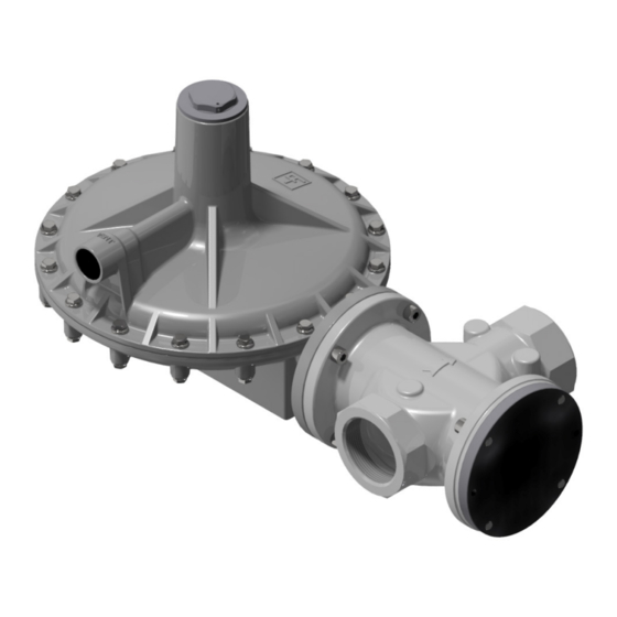
5.2 - PHYSICAL CHARACTERISTICS OF THE EQUIPMENT 5.2.1 - CIRVAL Fig. 5.9. Physical characteristics CIRVAL Clearances and dimensions CIRVAL Model Cirval 200 Cirval 300 6.6” 7.6” 10.0” 10.2” 15.4” 2.6” 3.9” 7.3” 11.0” 7.0” 10.1” 3/4" NPT 3/4" NPT Inlet 1-1/4”;... -
Page 49: Cirval + Ifm
5.2.2 - CIRVAL + IFM Fig. 5.10. Physical characteristics CIRVAL + IFM Clearances and dimensions CIRVAL + IFM Model Cirval 200 Cirval 300 6.6” 7.6” 10.0” 10.2” 15.4” 10.2” 15.4” 7.3” 11.0” 7.0” 10.1” 3/4" NPT 3/4" NPT Inlet 1-1/4”; 1-1/2”; 2” NPT 2”... -
Page 50: Cirval + Imd
5.2.3 - CIRVAL + IMD Fig. 5.11. Physical characteristics CIRVAL + IMD Clearances and dimensions CIRVAL + IMD Model Cirval 200 Cirval 300 6.6” 7.6” 10.0” 10.2” 15.4” 6.5” 8.4” 7.3” 11.0” 7.0” 10.1” 3/4" NPT 3/4" NPT Inlet 1-1/4”; 1-1/2”; 2” NPT 2”... -
Page 51: Cirval + La
5.2.4 - CIRVAL + LA Fig. 5.12. Physical characteristics CIRVAL + LA Clearances and dimensions CIRVAL + LA Model Cirval 200 Cirval 300 6.6” 7.6” 10.0” 10.2” 15.4” 8.2” 9.5” 7.3” 11.0” 6.5” 7.3” 7.0” 10.1” 3/4" NPT 3/4" NPT Inlet 1-1/4”;... -
Page 52: Method For Anchoring And Lifting The Equipment
5.3 - METHOD FOR ANCHORING AND LIFTING THE EQUIPMENT Before moving a load, make sure that its weight does not exceed the load capacity of the lifting means (and any other equipment) indicated on the specific plate. The unloading, transport and handling activities must be carried out by operators qualified for such opera- tions and specially trained: •... -
Page 53: Forklift Handling Method
5.3.1 - FORKLIFT HANDLING METHOD It is forbidden to: • pass under suspended loads; • move the load over the personnel working in the site/plant area. On forklift trucks it is forbidden to: • transport passengers; • lift people. NOTICE! The packaging must always be handled in a vertical position Proceed as described in tab. - Page 54 Step Operation Image Sollevare lentamente il carico di qualche decina di centimetri e veri carne la stabilità facendo attenzio- Inclinare il montante all’indietro (verso il posto guida) per avvantaggiare il momento ribaltante e Adeguare la velocità d ne che il baricentro del carico sia posizionato al centro delle forche di sollevamento. garantire una maggiore stabilità...
-
Page 55: Crane Handling Method
5.3.2 - CRANE HANDLING METHOD It is compulsory to use chains, ropes and eyebolts marked CE or marked with marks/conformity markings in accordance with the provisions in force in the place of installation. Do not use chains connected to each other by bolts. -
Page 56: Unpacking
• do not perform the installation operations; • contact PIETRO FIORENTINI S.p.A. communicating the data shown on the identification plate of the equipment. 5.4.1 - PACKAGING DISPOSAL Separate the various materials making up the packaging and dispose of them in compliance with the reg- ulations in force in the country of installation. -
Page 57: Storage And Environmental Conditions
PIETRO FIORENTINI S.p.A. recommends checking the state of conservation of the rubber parts for peri- ods of inactivity or storage exceeding 3 years. - Page 58 MEDIUM PRESSURE REGULATOR TRANSPORT AND HANDLING REV. A Operation, maintenance and warning manual...
-
Page 59: Installation
6 - INSTALLATION 6.1 - INSTALLATION PRE-REQUISITES 6.1.1 - ENVIRONMENTAL CONDITIONS For the safe use of the equipment, respecting the permitted environmental conditions, follow the data on the plate of the regulator and any accessories (refer to paragraph 2.8 "Identification plates applied"). The place of installation must be suitable for safe use of the equipment. -
Page 60: Checks Before Installation
6.1.2 - CHECKS BEFORE INSTALLATION In relation to its permissible pressure PS, the equipment does not require any additional upstream safety device to protect against possible overpressure when, for the upstream reduction station, the maximum downstream incidental pressure is: MIPd ≤ 1,1 PS MIPd = maximum value of downstream incidental pressure (for more information see UNI EN 12186:2014). -
Page 61: Installation-Specific Safety Warnings
6.2 - INSTALLATION-SPECIFIC SAFETY WARNINGS Before proceeding to the installation phase, make sure that the upstream and downstream valves installed on the line are closed. The installation could also take place in environments at risk of explosion and this implies the adoption of all the necessary prevention and protection measures. -
Page 62: General Information About Connections
6.3 - GENERAL INFORMATION ABOUT CONNECTIONS The equipment must be installed in the line with the arrow on the body facing in the direction of gas flow. The online installation must include: Pos. Description 1 shut-off valve upstream of the equipment. 2 vent valves placed one upstream and one downstream of the equipment. -
Page 63: Installation Locations Of The Regulator
When the device is used in gas pressure reduction stations, it must be installed at least according to the requirements of UNI EN 12186:2014 or UNI EN 12279:2007. The vents of the equipment must be channeled according to UNI EN 12186: 2014 or UNI EN 12279: 2007 or the standards in force at the place of installation of the equipment. -
Page 64: Installation Procedures
6.5 - INSTALLATION PROCEDURES 6.5.1 - INSTALLATION PROCEDURES OF EQUIPMENT Step Operation Place the equipment in the section of the line used for it. Place gaskets between the line flanges and the regulator flanges. Insert the bolts into the appropriate holes in the connecting flanges. Screw the bolts following the technical rules for tightening the flanges. - Page 65 To calculate the flow rate use the following formula: 1 − 0,002 = 345,92 V = gas speed in m/sec Q = gas flow rate in Sm³/h DN = nominal pipe diameter in mm Pd = outlet pressure of the regulator in barg All pneumatic connections to be made in the field must have pipes with a minimum internal diameter of 8 To avoid the collection of impurities and condensation in the pneumatic connections of the sensing lines it is necessary that:...
-
Page 66: Post-Installation And Pre-Commissioning Verification
In case there is a multiple sensing line, connect the connections of the equipment as follows: • 1 and 2 to the sensing line of the control head of the main regulator and the regulator with built-in monitor or monitor function;... -
Page 67: Commissioning/Maintenance Equipment
7 - COMMISSIONING/MAINTENANCE EQUIPMENT 7.1 - EQUIPMENT LIST Commissioning/maintenance equipment use • Mechanical maintenance technician; • Electrical maintenance technician; Operator qualification • Installer; • User technician. The PPE listed in this chart relates to the risk associated with the equipment. PPE required For the PPE required to protect against risks associated with the workplace, installation or operating conditions, refer to:... - Page 68 Ref. Type of equipment Image Hexagonal socket "T" wrench Phillips screwdriver Slotted screwdriver O-ring extraction tool Ring pliers Fiorentini special key Fiorentini special key Fiorentini special tool Special key for IFM, IMD monitor Torx wrench Tab. 7.43. MEDIUM PRESSURE REGULATOR REV.
-
Page 69: Equipment Needed For The Different Configurations
Nominal diameter of the reference configuration. Length, referring to equipment. Ref. Equipment reference. Type Type (size) or code of equipment. Tab. 7.44. CIRVAL ( + CIRVAL with monitor function) Equipment Model Ref. Type CIRVAL 200 CIRVAL 300 6 - 17 - 20 - 26... - Page 70 MEDIUM PRESSURE REGULATOR REV. A COMMISSIONING/MAINTENANCE EQUIPMENT Operation, maintenance and warning manual...
-
Page 71: Commissioning
8 - COMMISSIONING 8.1 - GENERAL WARNINGS 8.1.1 - SAFETY REQUIREMENTS FOR COMMISSIONING During commissioning, the risks posed by possible discharges of flammable or noxious gases into the atmosphere must be assessed. In the case of installation on distribution networks for natural gas, the risk of explosive mixture (gas/air) formation inside the pipes should be considered if an inerting procedure of the line is not adopted. -
Page 72: Preliminary Procedures For Commissioning
8.2 - PRELIMINARY PROCEDURES FOR COMMISSIONING Before commissioning the equipment, it is mandatory to ensure that any explosion hazard or source of ignition has been eliminated. Before commissioning, it is necessary to ensure that the conditions of use are in accordance with the characteristics of the equipment. -
Page 73: Verification Of The External Seal
8.3 - VERIFICATION OF THE EXTERNAL SEAL Completely sprinkle the equipment with a foaming solution (or equivalent control system) in order to verify the tightness of the external surfaces of the regulator and connections made during installation. 8.4 - CALIBRATION OF THE EQUIPMENT AND ACCESSORIES PRESENT To perform proper calibration of the equipment and the accessories present, refer to the accuracy class shown on the identification plates (see section 2.8). -
Page 74: Regulator Commissioning Procedure
The set-point value is recalled on the test certificate attached to each piece of equipment. Fig. 8.20. Commissioning of the CIRVAL regulator MEDIUM PRESSURE REGULATOR COMMISSIONING | REV. A Operation, maintenance and warning manual... - Page 75 Step Operation Partially open the drain cock (6). Very slowly open the upstream shut-off valve (V1). Check the pressure by referring to the pressure gauge (4) located upstream. Check the pressure of the line inlet pipe by referring to the upstream pressure gauge (4). To calibrate the regulator (1) to the required calibration value, turn the calibration ring nut (3): •...
-
Page 76: Commissioning Procedure Of The Cirval Regulator And The Regulator In Monitor Operation
8.6 - COMMISSIONING PROCEDURE OF THE CIRVAL REGULATOR AND THE REGULA- TOR IN MONITOR OPERATION Fig. 8.21. Commissioning of the CIRVAL regulator + regulator in monitor function Step Operation Remove the cap (7) from the main regulator (1). Remove the cap (10) from the regulator in inline monitor function (2). - Page 77 Step Operation Check that the calibration pressure of the main regulator (1) is at the set value by referring to the pressure value indicated by the downstream pressure gauge (5). Verify that the regulator with inline monitor function (2) is fully open (100%). The main regulator (1) is fully open, when the pressure indicated on the intermediate pressure gauge (4) is the same as the upstream pressure gauge (8).
-
Page 78: Commissioning Procedure Of The Regulator + Built-In Ifm Monitor
The set-point value is recalled on the test certificate attached to each piece of equipment. Fig. 8.22. Commissioning of the CIRVAL regulator + built-in IFM monitor MEDIUM PRESSURE REGULATOR COMMISSIONING | REV. A... - Page 79 Step Operation Remove the cap (7) from the main regulator (1). Remove the cap (10) from the built-in IFM monitor (2). Partially open the drain cock (6). Very slowly open the upstream shut-off valve (V1), checking that the downstream pressure (Pd) indicated by the downstream pressure gauge (5) does not exceed the required setting value by more than 50%.
-
Page 80: Commissioning Procedure Of The Regulator + Imd Built-In Monitor
The set-point value is recalled on the test certificate attached to each piece of equipment. Fig. 8.23. Commissioning of the regulator CIRVAL + IMD built-in monitor MEDIUM PRESSURE REGULATOR COMMISSIONING | REV. A... - Page 81 Step Operation Remove the cap (7) from the main regulator (1). Partially open the drain cock (6). Very slowly open the upstream shut-off valve (V1), checking that the downstream pressure (Pd) indicated by the downstream pressure gauge (5) does not exceed the required setting value by more than 50%. Check the pressure of the line inlet pipe by referring to the upstream pressure gauge (8).
-
Page 82: Commissioning Procedure Of The Cirval Regulator + Slam-Shut Valve La
COMMISSIONING PROCEDURE OF THE CIRVAL REGULATOR + SLAM-SHUT VALVE LA 8.9.1 - CHECK FOR LEAKAGE OF THE LA SLAM-SHUT VALVE Fig. 8.24. Commissioning of the CIRVAL regulator with LA slam-shut valve Step Operation Check that the slam-shut valve is in the closed position. - Page 83 MEDIUM PRESSURE REGULATOR COMMISSIONING REV. A Operation, maintenance and warning manual...
-
Page 84: Commissioning Of Cirval Regulator + La Slam-Shut Valve
8.9.2 - COMMISSIONING OF CIRVAL REGULATOR + LA SLAM-SHUT VALVE Fig. 8.25. Commissioning of the CIRVAL regulator with LA slam-shut valve Step Operation Check that the drain cock (6) is partially open. Check that the LA slam-shut valve is in the closed position. - Page 85 Step Operation If the downstream pressure (Pd) is not at the required calibration value, act as below: • value of downstream pressure (Pd) less than the required calibration value: load the calibration spring by turning the adjustment ring nut (3) clockwise •...
-
Page 86: Calibration Procedure For La Slam-Shut Valve (La-Bp, La-Mp, La-Tr)
8.9.3 - CALIBRATION PROCEDURE FOR LA SLAM-SHUT VALVE (LA-BP, LA-MP, LA-TR) Fig. 8.26. LA Slam-shut valve calibration CALIBRATION OF SPRING TO TRIP FOR MAXIMUM PRESSURE Step Operation Increase the downstream pressure to the slam-shut valve's tripping value by connecting an external pressure source to the drain valve (fig. - Page 87 CALIBRATION OF SPRING FOR TRIPPING BY MINIMUM PRESSURE (IF ANY) Step Operation Partially open the drain cock (fig. 8.20, ref. 6) in the atmosphere and keep it open for the next steps. Turn the adjustment ring nut counterclockwise (fig. 8.20, ref. 3) of the regulator to decrease the downstream pressure (Pd) to the minimum pressure required for the slam-shut valve to trip.
-
Page 88: Regulation Line Commissioning Procedure Cirval, Regulator With In-Line Monitor Function + Slam-Shut Valve The
8.10 - REGULATION LINE COMMISSIONING PROCEDURE CIRVAL, REGULATOR WITH IN-LINE MONITOR FUNCTION + SLAM-SHUT VALVE THE Fig. 8.27. Commissioning of CIRVAL regulator + regulator with online monitor function + LA Step Operation Partially open the drain cock (6). Remove the cap (7) from the main regulator (2). - Page 89 Step Operation Pull the slam-shut valve reset stem outward until the LA slam-shut valve is engaged. Check the calibration pressure of the regulator with in-line monitor function in the pressure gauge (5) after inserting the plug (10) into the regulator with in-line monitor function (1). If the downstream pressure (Pd) is not at the required calibration value, act as below: •...
- Page 90 MEDIUM PRESSURE REGULATOR COMMISSIONING | REV. A Operation, maintenance and warning manual...
-
Page 91: Fault Finding And Troubleshooting
• qualified and authorized for the activities inherent to the equipment. No liability related to personal injury or property damage can be attributed to PIETRO FIORENTINI S.p.A. for interventions: • other than those described;... -
Page 92: Specific Qualification Of The Operator
9.2 - SPECIFIC QUALIFICATION OF THE OPERATOR Commissioning • Mechanical maintenance technician; • Electrical maintenance technician; Operator qualification • Installer; • User technician. The PPE listed in this chart relates to the risk associated with the equipment. PPE required For the PPE required to protect against risks associated with the workplace, installation or operating conditions, refer to: •... - Page 93 MEDIUM PRESSURE REGULATOR TROUBLESHOOTING REV. A Operation, maintenance and warning manual...
-
Page 94: Troubleshooting Tables
9.4 - TROUBLESHOOTING TABLES 9.4.1 - CIRVAL REGULATOR TROUBLESHOOTING CIRVAL 300 LID DETAIL CIRVAL 300 BALANCING BLOCK Fig. 9.29. Troubleshooting CIRVAL Fault Possible causes Intervention Main diaphragm (321) broken Replace Leakage from the regulator vent in Relief valve (307) not calibrated... - Page 95 Damaged valve seat (102) Replace Downstream pressure (Pd) increases O-ring (104) of the valve seat damaged Replace in static VALID ONLY FOR CIRVAL 300 O-ring (215) of reinforced gasket dam- Replace aged O-ring (202) of the stem damaged Replace Balancing diaphragm (209) damaged...
-
Page 96: Troubleshooting Of Regulator Cirval With Monitor Function
9.4.2 - TROUBLESHOOTING OF REGULATOR CIRVAL WITH MONITOR FUNCTION CIRVAL 300 LID DETAIL CIRVAL 300 BALANCING BLOCK Fig. 9.30. Troubleshooting CIRVAL in monitor function Fault Possible causes Intervention Main diaphragm (321) broken Replace Leakage from the regulator vent in Relief valve (307) not calibrated... - Page 97 Damaged valve seat (102) Replace Downstream pressure (Pd) increases O-ring (104) of the valve seat damaged Replace in static VALID ONLY FOR CIRVAL 300 O-ring (215) of reinforced gasket dam- Replace aged O-ring (202) of the stem damaged Replace Balancing diaphragm (209) damaged...
-
Page 98: Incorporated Ifm Monitor Troubleshooting
Clean and if necessary replace Leakage from the regulator vent in worn out dispensing VALID ONLY FOR CIRVAL 300 Clean and if necessary replace Dirty or worn O-ring (216, 217) VALID ONLY FOR CIRVAL 200 Clean and if necessary replace... - Page 99 Leakage from the regulator vent in Damaged valve seat (102) Replace static O-ring (104) of the valve seat damaged Replace VALID ONLY FOR CIRVAL 300 O-ring (215) of reinforced gasket dam- Replace aged O-ring (202) of the stem damaged Replace...
- Page 100 Replace aged O-ring (202) of the stem damaged Replace Lever (305) stuck Clean VALID ONLY FOR CIRVAL 300 Clean Anti-pumping valve (319) clogged Obstructed anti-freezing device Clean Lack of O-ring sealing (111) Clean and if necessary replace...
- Page 101 MEDIUM PRESSURE REGULATOR TROUBLESHOOTING REV. A Operation, maintenance and warning manual...
-
Page 102: Incorporated Imd Monitor Troubleshooting
9.4.4 - INCORPORATED IMD MONITOR TROUBLESHOOTING Fig. 9.32. Incorporated IMD monitor troubleshooting Fault Possible causes Intervention Diaphragm (411) broken Replace O-ring (202) of the balance block dirty Clean and if necessary replace Leakage from the IMD built-in mon- or worn out itor vent in dispensing O-ring (224) of the balance block dirty Clean and if necessary replace... - Page 103 Fault Possible causes Intervention Diaphragm (411) broken Replace O-ring (202) of the balance block dirty Clean and if necessary replace or worn out Downstream pressure (Pd) increases O-ring (224) of the balance block dirty Clean and if necessary replace in static or worn out Dirty or worn flange O-ring (422) Clean and if necessary replace...
-
Page 104: La Slam-Shut Valve Troubleshooting
9.4.5 - LA SLAM-SHUT VALVE TROUBLESHOOTING If the built-in slam-shut valve has tripped, close the upstream and downstream shut-off valves (V1 and V2) of the line and relieve the pressure before any operation. Fig. 9.33. LA slam-shut valve troubleshooting Fault Possible causes Intervention Failure of the slam-shut valve to... -
Page 105: Uninstallation And Disposal
10 - UNINSTALLATION AND DISPOSAL 10.1 - GENERAL SAFETY WARNINGS Ensure that there are no effective ignition sources in the work area set up for equipment de-installation and/or disposal. Before proceeding with uninstallation and disposal operations, ensure that the equipment is secured by disconnecting it from all power supplies. -
Page 106: Disposal Information
10.5 - DISPOSAL INFORMATION Please remember to comply with the laws in force in the country where the equipment is installed. Illegal or improper disposal will result in the application of the penalties provided for in the regulations in force in the country of installation. Proper disposal avoids harm to humans and the environment and promotes the reuse of valuable raw materials. - Page 107 By using non-original replacement parts PIETRO FIORENTINI S.p.A. the stated performance cannot be guaranteed. It is recommended to use the original PIETRO FIORENTINI S.p.A. replacement parts PIETRO FIORENTINI S.p.A. is not responsible for damage caused by the use of non-original replacement parts or components. 11.2 - HOW TO REQUEST REPLACEMENT PARTS For specific information, consult the PIETRO FIORENTINI S.p.A.
- Page 108 MEDIUM PRESSURE REGULATOR RECOMMENDED SPARE PARTS | REV. A Operation, maintenance and warning manual...
- Page 109 12 - CALIBRATION TABLES 12.1 - CALIBRATION TABLE CIRVAL 200 The setting ranges of the springs for the CIRVAL regulator are shown in the following tables: CIRVAL 200 BP Pos. Spring article code Spring color Min. Max. 64470068GI Yellow 0.2321 0.3481...
- Page 110 12.2 - CALIBRATION TABLE CIRVAL 300 CIRVAL 300 BP Pos. Spring article code Spring color Min. Max. 64470382NE Black 0.2321 0.3916 2700525 Orange 64470301GI Yellow 0.4061 0.5801 2700645 64470302VI Purple 0.5946 1.2038 2700999 Grey d = Wire Diameter (mm) Lo = Spring Length (mm) De = External Diameter (mm) Min./Max. = pressure (psi) Tab.
- Page 111 MEDIUM PRESSURE REGULATOR CALIBRATION TABLES REV. A Operation, maintenance and warning manual...
- Page 112 TM0029USA...
Need help?
Do you have a question about the CIRVAL and is the answer not in the manual?
Questions and answers