Table of Contents
Advertisement
Quick Links
S
UPERMICR
R
X10SAE
Q
r
g
uICk
eferenCe
uIde
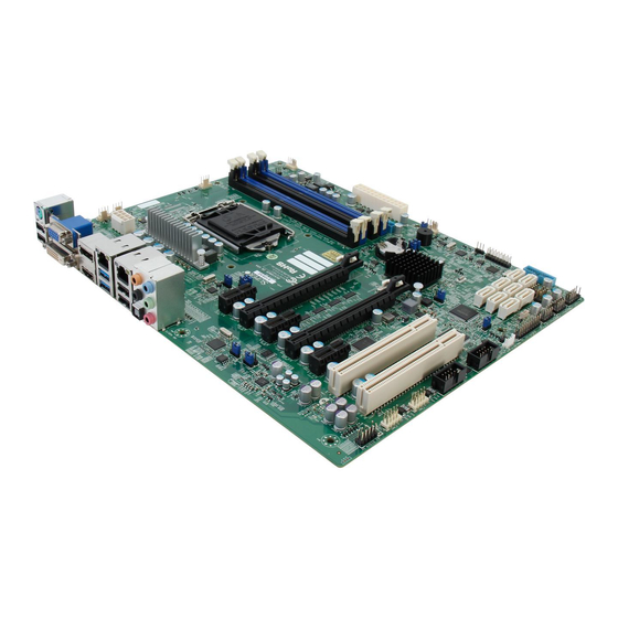
Motherboard Layout and Features
JPAC1
JPL2
JSPDIF_OUT
JHD_AC1
BAR CODE
MAC CODE
1394 CODE
BIOS
LICENSE
JPME2
Intel PCH
BATTERY
JBT1
JPME1
JBR1
BIOS
USB12/13(3.0)
SP1
JD1
USB 14/15(3.0)
JF1
JLED1
CPU Installation
Heatsink Installation
Heatsink
with Fan
Mounting Hole
Motherboard
Note: Graphics shown in this quick reference guide are for illustration only. Your components may or may not look exactly the same as drawings shown in this guide.
C
I
ontaCt
nformatIon
• www.supermicro.com (Email: support@supermicro.com)
• Manuals: http://www.supermicro.com/support/manuals
• Drivers & Utilities: ftp://ftp.supermicro.com
• Safety: http://www.supermicro.com/about/policies/safety_information.cfm
USB 2/3
USB10/11(3.0)
HDMI/DP
VGA/DVI
HD AUDIO
USB 0/1
LAN2
LAN1
JPW2
JPL1
JI2C1
JI2C2
X10SAE
CPU
Always populate blue sockets first;
Unbuffered ECC/Non-ECC DDR3 DIMM required
DIMMA1
DIMMA2
DIMMB1
DIMMB2
JPW1
= mounting hole
Front Panel Control (JF1)
Power LED
LED_Anode+
LED_Anode+
HDD LED
NIC1 LED
LED_Anode+
LED_Anode+
NIC2 LED
OH/Fan Fail LED
LED_Anode+
X
X
Reset
Reset Button
Ground
Power Button
Ground
PWR
2
1
P
C
aCkage
ontents
(Applies to individual-pack only)
• One (1) Supermicro Motherboard
• Eight (8) SATA Cables
• One (1) I/O Shield
• One (1) Quick Reference Guide
Jumpers, Connectors and LED Indicators
Jumpers
JBT1
CMOS Clear
JI
2
C1/JI
2
C2
SMB to PCI Slots
JHD_AC1
High Definition (HD) Audio Enable
JPAC1
Front Panel Audio Enable
JPI1
1394_1/1394_2 Enable
JPL1/JPL2
LAN1/LAN2 Enable
JWD1
Watch Dog Enable
Connectors
1394_1/2
1394 Connectors 1/2
Audio FP
Front Panel Audio Header
HD AUDIO
High-Definition Audio Connectors (on the I/O back panel)
BATTERY
Onboard Battery
COM1/COM2
COM1/COM2 Port Headers
Fan1~Fan5
System/CPU Fan Headers (Fan1: CPU Fan)
HDMI/DP
Backplane HDMI(High-Definition Multimedia Interface)/DP Audio Port
JD1
Speaker/buzzer (Pins 3-4: Buzzer, Pins 1~4: External Speaker)
JF1
Front Panel Control Header
JL1
Chassis Intrusion Header
JLED1
Power LED Indicator Header
JPW1
24-pin ATX Main Power Connector (Required)
JPW2
+12V 8-pin CPU power Connector (Required)
JSD1
SATA DOM (Device_On_Module) Power Connector
JSPDIF_OUT
Sony/Philips Digital Interface (SPDIF)_Out Header
JSTBY1
Standby Power Header
JTPM1
Trusted Platform Module/Port 80 Connector
JVR1/JVR2
PWM SMB programming headers 1/2(for debugging only)
JWOR1
Wake_On-Ring Header
KB/Mouse
Keyboard/Mouse Connectors
LAN1/LAN2
Gigabit (RJ45) Ports (LAN1/2)
SP1
Internal Speaker/Buzzer
A-SATA0/A-SATA1
(ASMedia) Serial ATA (SATA 3.0) Ports 0/1 (6Gb/sec)
I-SATA0-I-SATA5
(Intel) Serial ATA (SATA 3.0) Ports 0-5 (6Gb/sec)
Slot 3/Slot 5/Slot 7
PCI-Express 2.0 x1 Slots
Slot 6
PCI-Express 3.0 x16 Slot (x8 if Slot 4 is used)
Slot 4
PCI-Express 3.0 x8 in x16 Slot
Slot 1, Slot 2
PCI 33MHz Slot (5V)
T-SGPIO 1/2
Serial_Link General Purpose I/O Connection Headers 1/2
USB 0/1, 2/3
Backpanel USB 2.0 Ports 0/1, 2/3
USB 10/11
Backpanel USB 3.0 Ports 10/11
USB 4/5, USB 6/7, USB 8/9
Front Panel Accessible USB 2.0 Headers 4/5, 6/7, 8/9
USB 3.0 12/13, 14/15
Front Panel Accessible USB 3.0 Headers 12/13, 14/15
VGA/DVI
Backpanel VGA/DVI (Digital Video Interface) Port
LED Indicators
LED1
Onboard Standby PWR LED
Green: Solid on
Note: Refer to Chapter 2 of the User Manual for detailed information on jumpers, connectors, and LED indicators.
Memory Support
The X10SAE supports up to 32GB of Unbuffered (UDIMM) DDR3 ECC/non-
(See Chpt. 2)
ECC 1600/1333/1066 MHz in 4 memory slots. Populating these DIMM modules
with a pair of memory modules of the same type and same size will result in
Off (Disabled)
interleaved memory, which will improve memory performance.
Pins 1-2 (Enabled)
Note: For memory optimization, use only DIMM modules that have been validated by Supermicro.
Pins 1-2 (Enabled)
For the latest memory updates, please refer to our website at http://www.supermicro.com/
Pins 1-2 (Enabled)
products/motherboard.
Pins 1-2 (Enabled)
DIMM Memory Installation
Pins 2-3 (NMI)
DIMMA1
DIMMA2
DIMMB1
DIMMB2
Memory Population Guidelines
When installing memory modules, the DIMM slots should be populated in the fol-
lowing order: DIMMA2, DIMMB2, then DIMMA1, DIMMB1.
•
Always use DDR3 DIMM modules of the same size, type and speed.
•
Mixed DIMM speeds can be installed. However, all DIMMs will run at the speed
of the slowest DIMM.
Recommended Population (Balanced)
DIMMA2
DIMMB2
DIMMA1
1GB
1GB
1GB
1GB
1GB
2GB
2GB
2GB
2GB
2GB
4GB
4GB
4GB
4GB
4GB
8GB
8GB
8GB
8GB
8GB
Note: Up to 32GB of memory are supported. See chapter 2 of the User Manual for
complete memory population information.
Back Panel IO Connectors
Backplane I/O Panel
A. USB 2.0 Port 0
G. Display/Port Connector
B. USB 2.0 Port 1
H. USB 3.0 Port 10
C. Keyboard/Mouse
I. USB 3.0 Port 11
D. DVI Port
J. Gb LAN Port 1
E. VGA Port
K. USB 2.0 Port 2
F. HDMI Port
L. USB 2.0 Port 3
C
E
G
B
D
F
Power On
A
Note: Refer to Chapter 2 of the User Manual for detailed information on memory support and CPU/
motherboard installation instructions.
Towards the CPU
DIMMB1
Total System Memory
2GB
1GB
4GB
4GB
2GB
8GB
8GB
4GB
16GB
16GB
8GB
32GB
N. SPDIF Out
O. Surround Out
P. Center/LFE Out
Q. Mic In
R. Line Out
S. Line In
J
M
P
S
HD Audio
I
L
O
R
H
K
N
Q
Advertisement
Table of Contents


Need help?
Do you have a question about the X10SAE and is the answer not in the manual?
Questions and answers