Chapters
Table of Contents
Troubleshooting

Related Manuals for Omron SYSMAC CS1W-CLK13


Summary of Contents for Omron SYSMAC CS1W-CLK13
- Page 1 Cat. No. W370-E1-06 SYSMAC CS1W-CLK13 (H-PCF Cable) CS1W-CLK12-V1 (H-PCF Cable) CVM1-CLK12 (H-PCF Cable) CS1W-CLK53 (GI Cable) CS1W-CLK52-V1 (GI Cable) CVM1-CLK52 (GI Cable) Optical Ring Controller Link Units OPERATION MANUAL...
- Page 2 CS1W-CLK13 (H-PCF Cable) CS1W-CLK12-V1 (H-PCF Cable) CVM1-CLK12 (H-PCF Cable) CS1W-CLK53 (GI Cable) CS1W-CLK52-V1 (GI Cable) CVM1-CLK52 (GI Cable) Optical Ring Controller Link Units Operation Manual Revised September 2007...
- Page 4 OMRON Product References All OMRON products are capitalized in this manual. The word “Unit” is also capitalized when it refers to an OMRON product, regardless of whether or not it appears in the proper name of the product.
- Page 5 CONTROLLER LINK UNIT Unit version 1.2 Lot No. 040801 0000 Ver.1.2 OMRON Corporation MADE IN JAPAN Confirming Unit Versions with Support Software CX-Programmer version 5.0 or later can be used to confirm the unit version in the Unit Manufacturing Information.
- Page 6 Using the Unit Version Labels Unit version labels are provided with the product. These labels can be attached to the front of previous Controller Link Units to differentiate between Controller Link Units of different unit versions. Unit Version Notation The unit versions are indicated in this manual as follows: Notation in product nameplate Notation in this manual Remarks...
- Page 7 Checking the CX-Integrator Data Link Setting Tool Version 1,2,3... 1. Start the CX-Integrator and select Tool - Start Data Link. 2. In the Select Network Dialog Box, select 1 Controller Link and click the OK But- ton. 3. The Data Link Table Setting Tool (Data Link Component) will start. Select Help - About Datalink Component...
- Page 8 OMRON. No patent liability is assumed with respect to the use of the information contained herein. Moreover, because OMRON is con- stantly striving to improve its high-quality products, the information contained in this manual is subject to change without notice.
- Page 10 TABLE OF CONTENTS PRECAUTIONS ........xvii Intended Audience .
- Page 11 TABLE OF CONTENTS SECTION 6 Message Service........141 Introduction .
- Page 12 TABLE OF CONTENTS SECTION 11 Adding Nodes and Editing Active Data Link Tables..299 11-1 Adding Nodes in Token-ring Mode ..........11-2 Changing the Data Link Tables with Active Data Links .
- Page 13 TABLE OF CONTENTS...
- Page 14 About this Manual: This manual describes the installation, setup, and operation of the CS1W-CLK13, CS1W-CLK12-V1, CVM1-CLK12, CS1W-CLK53, CS1W-CLK52-V1, and CVM1-CLK52 Optical Ring Controller Link Units for CS-series, CVM1, and CV-series PLCs and includes the sections described below. The Controller Link Units are used to connect these PLCs to an Optical Ring Controller Link Network. The following three manuals are related to application of the Controller Link Network.
- Page 15 Appendix A provides a list of standard OMRON products related to Controller Link Networks, Appendix B provides easy reference to the CPU Unit memory areas related to Controller Link Net- works, Appendix C provides information on CS-series Optical Bus Controller Link Units (production to be discontinued), and Appendix D provides information on handling Optical Fiber Cables.
-
Page 16: Table Of Contents
PRECAUTIONS This section provides general precautions for using the Controller Link Unit and related devices. The information contained in this section is important for the safe and reliable application of the Controller Link Unit. You must read this section and understand the information contained before attempting to set up or operate a Controller Link Unit. -
Page 17: Intended Audience
It is extremely important that a PLC and all PLC Units be used for the speci- fied purpose and under the specified conditions, especially in applications that can directly or indirectly affect human life. You must consult with your OMRON representative before applying a PLC System to the above mentioned appli- cations. -
Page 18: Operating Environment Precautions
Operating Environment Precautions • The PLC outputs may remain ON or OFF due to deposition or burning of the output relays or destruction of the output transistors. As a counter- measure for such problems, external safety measures must be provided to ensure safety in the system. -
Page 19: Applications Precautions
Applications Precautions • Locations subject to shock or vibration. !Caution Take appropriate and sufficient countermeasures when installing systems in the following locations: • Locations subject to static electricity or other forms of noise. • Locations subject to strong electromagnetic fields. •... - Page 20 Applications Precautions • Always use the power supply voltages specified in the operation manuals. An incorrect voltage may result in malfunction or burning. • Take appropriate measures to ensure that the specified power with the rated voltage and frequency is supplied. Be particularly careful in places where the power supply is unstable.
-
Page 21: Conformance To Ec Directives
The Controller Link Units conform to EMC Directives as follows: EMC Directives OMRON devices that comply with EC Directives also conform to the related EMC standards so that they can be more easily built into other devices or the overall machine. The actual products have been checked for conformity to EMC standards (see the following note). - Page 22 2) for EMS but, depending on the backup power supply used, they may not conform to the standard for immunity to surges (IEC61000-4-5). In order to ensure conformance, either use an OMRON S82K-series power supply, which is the recommended backup power supply, or take surge counter- measures at the primary side.
- Page 23 Conformance to EC Directives xxiv...
- Page 24 SECTION 1 Features and System Configuration This section provides basic information on Controller Link Networks, and gives the reader an overview of what Controller Link Networks can do and how best to use them. Overview ........... . . 1-1-1 What Is the Controller Link? .
-
Page 25: Overview
What Is the Controller Link? The Controller Link is an FA network that can send and receive large data packets flexibly and easily among the OMRON C200HX/HG/HE Programma- ble Controllers (PLCs), CS-series PLCs, CVM1 PLCs, CV-series PLCs, and IBM PC/AT or compatible computers. - Page 26 Section 1-1 Overview Optical Bus or Optical Optical Systems are supported by CS-series, CVM1, and CV-series PLCs. Ring System (H-PCF Token-ring Mode Cable) CVM1-CLK12 CS1W-CLK12-V1 Controller Link Unit Controller Link Unit (Token-ring mode) (Token-ring mode) CVM1 or CV-series CS-series PLC Computer H-PCF Optical Fiber Cable Backup power...
- Page 27 Overview Section 1-1 Optical Bus or Optical Optical Systems are supported by CS-series, CVM1, and CV-series PLCs. Ring System (GI Cable) Token-ring Mode CS1W-CLK52-V1 CVM1-CLK52 Controller Link Unit Controller Link Unit (Token-ring mode) (Token-ring mode) CVM1 or CV-series CS-series PLC Computer GI Optical Fiber Cable Backup power...
- Page 28 Section 1-1 Overview Data Links Data links allow the constant sharing of data in predetermined data areas between nodes, between PLCs, or between a PLC and an IBM PC/AT or com- patible computer on the network. Data links do not require the use of commu- nications programs on the PLC (CPU Unit) or IBM PC/AT or compatible computer.
- Page 29 CMND The CMND instruction issues a command to read or write data of other nodes, control, or read error logs. With the Controller Link Unit, OMRON’s command protocol called “FINS commands” is used. RAS performs real-time monitoring of the network status. If an error occurs in the network, RAS records and displays the time and contents of the error.
-
Page 30: Features
Overview Section 1-1 Optical transmission path Bypass IBM PC/AT or Power interruption compatible computer Backup power supply (24 VDC) Transmission Path In the token-ring mode in an Optical Ring System (H-PCF cable or GI cable), Duplication data transmission will be unaffected even by a cable or connector break at one location in the ring connection. - Page 31 Section 1-1 Overview All other Units: 1,000 words max. Number of send and receive words per node CS-series PLCs (Unit Ver. 1.2 or later): 20,000 words max. Pre-Ver. 1.2: 12,000 words max. CVM1, CV-series PLCs: 8,000 words max. Personal computer with PCI Board: 62,000 words max. Data links can be automatically set, or they can be set by the user to freely change the sizes of the data areas used.
- Page 32 Section 1-1 Overview Optical Ring System (GI Cable) • Controller Link Units for CS-series Programmable Controllers • Controller Link Units for CVM1 and CV-series Programmable Control- lers • Controller Link Boards for personal computers with PCI bus Optical Bus System •...
- Page 33 Section 1-1 Overview Duplex settings for Controller Link Units can be performed with CX-Pro- grammer Ver. 3.0 or later. 2. Active/standby switchover will take place when the following errors occur at the active Controller Link Unit. • EEPROM error • Error in the communications controller’s transmitter •...
- Page 34 Overview Section 1-1 Two Controller Link Units that are used in duplex operation are treated as just one node in the Controller Link Network and can be used in the same way as pre-version 1 models (i.e., without “-V1” at the end of the model number). The operating status of the active Controller Link Unit is constantly stored in the standby Controller Link Unit and so operation continues smoothly if there is an active/standby switchover between the Units.
- Page 35 Overview Section 1-1 Restrictions Automatic data link creation with 1:N allocations cannot be performed if ver- sion-1 models and pre-version-1 models are used together in the same net- work. Manually Created Data Applicable Models: Link Table Changes • CS1W-CLK12-V1 and CS1W-CLK52-V1 Controller Link Units with lot during Data Link numbers 0306@@_@@@@ or later (manufactured after May, 2003).
-
Page 36: Specifications And Configurations
Section 1-2 Specifications and Configurations Specifications and Configurations 1-2-1 System Configuration A single Controller Link Network is configured as shown in the following dia- gram. Optical Bus or Optical Ring System (H-PCF Cable) Token-ring Mode CS1W-CLK12-V1 CVM1-CLK12 Controller Link Unit Controller Link Unit (Token-ring mode) (Token-ring mode) - Page 37 Specifications and Configurations Section 1-2 Token-bus Mode CS1W-CLK12-V1 CVM1-CLK12 IBM PC/AT or CS1W-CLK11 Controller Link Unit Controller Link Unit compatible computer Controller Link Unit Computer (Token-bus mode) (Token-bus mode) CVM1 or CV-series PLC CS-series PLC CS-series PLC H-PCF Optical Fiber Cable 3G8F5-CLK11 3G8F7-CLK12-EV1 (daisy-chain connection)
-
Page 38: Models
Section 1-2 Specifications and Configurations Units can be used in duplex operation only when the new version-1 Controller Link Units are mounted on a CS1D PLC. Either a CS1D Duplex System or a CS1D Simplex System allows duplex operation of Units. Controller Link Networks can include both nodes with Units used in duplex operation (new models) and nodes without Units used in duplex operation (new models and/or existing models) as well as CVM1 and CV-series Control-... -
Page 39: General Specifications
Section 1-2 Specifications and Configurations 1-2-3 General Specifications General specifications are the same for the CS-series, CVM1, and CV-series PLCs. 1-2-4 Communications Specifications Optical Ring System Items Specifications Type Optical Ring (H-PCF cable) Optical Ring (GI cable) Communications method N:N token-ring method (token-ring mode) N:N token-bus method (token-bus mode) Code Manchester code... -
Page 40: Controller Link Unit Models And Plcs
Specifications and Configurations Section 1-2 Note 1. The maximum distance between nodes depends on the connector and ca- ble processing methods. 2. With the token-bus method, the maximum number of nodes in an Optical Bus System with optical bus nodes (i.e., model numbers ending in CLK11) is 32 (node addresses 1 to 32). - Page 41 Section 1-2 Specifications and Configurations Mounting Position and Number of Mountable Units CS1W-CLK11 Optical Bus Install onto a CPU Backplane or CS-series Expansion Backplane (Classified Controller Link Unit as a CPU Bus Unit.) 4 Units maximum including other types Unit CPU Backplane 2/3/5/8/10 slots Of these slots,...
- Page 42 Section 1-2 Specifications and Configurations CS1W-CLK12 Optical Ring Install onto a CPU Backplane or CS-series Expansion Backplane (Classified Controller Link Unit as a CPU Bus Unit.) 4 Unit maximum including other types Unit CPU Backplane 3/5/10 slots Of these 14, 16, or 21 slots, installation is possible in up to...
- Page 43 Section 1-2 Specifications and Configurations Mounting Position and Number of Mountable Units CS1W-CLK53 and CS1W- CS1 or CS1-H CPU Unit CLK52-V1 Optical Ring Install the Controller Link Unit onto a CPU Backplane or CS-series Expansion Controller Link Units Backplane. (The Controller Link Unit is classified as a CPU Bus Unit.) 4 maximum including other types of Controller Link Units Unit...
-
Page 44: Devices Required For Connection
Specifications and Configurations Section 1-2 CS1W-CLK52 Optical Ring Install the Controller Link Unit onto a CPU Backplane or CS-series Expansion Controller Link Unit Backplane. (The Controller Link Unit is classified as a CPU Bus Unit.) 4 maximum including other types of Controller Link Units Unit CPU Backplane... - Page 45 Name Model Recommended Manufacturer replacement Optical Connector S3200-COCF2011 S3200-COCF2071 OMRON S3200-COCF2511 S3200-COCF2571 Note 1. Either full-lock or half-lock connectors can be used in a Controller Link Net- work, but we recommend full-lock connectors to prevent accidental discon- nections during operation.
- Page 46 Section 1-2 Specifications and Configurations Optical Fiber Cables with Connectors (Indoor Use Only) The following glue-and-polish Optical Fiber Cables are available with Connec- tors already attached. Specifications Length Model Optical Fiber Cable Connectors: S3200-CN201-20-20 S3200-COCF2071 S3200-CN501-20-20 ⇓ 10 m S3200-CN102-20-20 S3200-COCF2071 15 m S3200-CN152-20-20...
- Page 47 Name Model Specifications Manufacturer Optical Connector S3200-CAK1062 Optical connector: OMRON Assembly Tool S3200-COCF2011/ 2511 This manual does not provide details on Optical Fiber Cable preparation. For details, refer to the instructions provided with the S3200-CAK1062 Assembly Tool. Optical Ring System...
-
Page 48: Programming Devices
Section 1-2 Specifications and Configurations is ambient temperature, and λ is the peak wave- Note is fiber length in km, T length of the test light source. Connectors ST Connector Note When connecting Controller Link Units (CS1W-CLK53 or CS1W-CLK52-V1) used in duplex operation in a CS1D System using a short GI cable, take note of the following points. - Page 49 Section 1-2 Specifications and Configurations 2. Use the CX-Integrator to set data link tables with more than 1,000 send words per node. For information on checking the CX-Integrator version number, refer to Checking the CX-Integrator Data Link Setting Tool Version on page viii.
- Page 50 Specifications and Configurations Section 1-2 Controlling the Network Using a Computer as a Node IBM PC/AT or compatible Controller Link Support Software Controller Link Support Board Setting data link tables Software External Model number Applicable PLCs Remarks appearance Controller Purchased sep- C200HW-ZW3AT2-EV2 CS-series, C200HX/ For IBM PC/AT or...
- Page 51 Section 1-2 Specifications and Configurations 3. Controller Link Support Software cannot be used to set automatic creation of data links with 1:N allocations or to change data link tables while data links are running (supported by CS1W-CLK12-V1 and CS1W-CLK52-V1 for lot number 0306@@_@@@@ or later and CS1W-CLK13/53 only). Use the CX-Net in CX-Programmer version 3.2 or later to set these functions.
-
Page 52: Backup Power Supply
Backup Power Supply The following table shows the input specifications required for backup power Specifications supplies to Controller Link Units and Boards. Be sure that the backup power supply being used meets these specifications. (We recommend the OMRON S82K Series.) Item Specification... -
Page 53: Selecting Communications Functions
Section 1-3 Selecting Communications Functions 2. If the backup power supply goes on or off, any data being transmitted at that moment will be corrupted. 3. Do not use the same power source to supply the backup power supply and the PLC/computer. -
Page 54: Application Precautions
Section 1-5 Application Precautions Note When I/O tables for configurations with Communications Units used in duplex operation are created, the Unit with the lower slot number will be designated as the active Unit and the Unit with the higher slot number will be designated as the standby Unit. To re- verse this designation, edit the I/O tables offline and transfer them to the PLC. - Page 55 Section 1-5 Application Precautions Note Routing tables are not required if all of the CVM1 and CV-series CPU Units if the Controller Link Network were manufactured on or after May 1996. Independent Controller Link Network Routing tables not necessary Manufactured after May 1996 Manufactured after May 1996 Note The manufacturing date can be determined from the four-digit lot number on...
- Page 56 Section 1-5 Application Precautions • When an Optical Ring System is used, the same transmission path format settings must be made for all of the nodes. The network cannot be set up correctly if these settings are different. • When Optical Bus (CLK11) and Optical Ring (H-PCF cable) (CLK12, CLK12-V1, or CLK13) Controller Link Units are used in combination, observe the following precautions.
- Page 57 Section 1-5 Application Precautions • For details on Controller Link Unit current consumption, refer to Controller Link Unit Models and PLCs on page 17. For details on current consump- tion of each Unit, refer to the SYSMAC CS Series Programmable Control- lers Operation Manual (W339).
- Page 58 SECTION 2 Basic Procedures This section describes the basic procedures for using the Controller Link Unit. The settings required for each of the functions are also explained briefly. For more details, refer to the subsequent sections on individual functions. Data Links Procedures ......... . 2-1-1 Manually Setting Data Links .
- Page 59 Section 2-1 Data Links Procedures Data Links Procedures 2-1-1 Manually Setting Data Links When the data link mode is set for manual data link table creation, the data link tables can be input using the Controller Link Support Software or CX-Pro- grammer.
- Page 60 Section 2-1 Data Links Procedures 6. Set the software switches. Contents Method Nodes Page Transmission path By Programming All nodes. 79, 82 format setting Device for PLC, includ- ing Programming Con- sole. (See note a.) Data link manual/ By Programming Data link startup node only.
- Page 61 Section 2-1 Data Links Procedures Note (a) Data link Start/Stop Bit (N= unit number): Word 0 of DM30000 + 100 × N CS Series: CVM1/CV Series: Word 0 of DM 2000 + 100 × N (b) The data links will not start if there is an error in the data link ta- bles in the startup node.
- Page 62 Section 2-1 Data Links Procedures 5. Make duplex settings for Communications Units. Create I/O tables. Contents Method Nodes Page Make duplex settings for Use the Programming Duplex nodes Communications Units Device. (in PLC Setup). Create the I/O tables. Use the SYSMAC Sup- All nodes (See note.) port Software or Pro-...
- Page 63 Section 2-1 Data Links Procedures 7. Set the parameters for automatic data link creation. Equality Layout: Previous Pattern (Supported by CS1W-CLK13, CS1W- CLK12-V1, CS1W-CLK53, CS1W-CLK52-V1, CVM1-CLK12, and CVM1- CLK52) Contents Method Nodes Page Set the data link mode to Use a Programming Data link startup node manual or automatic.
- Page 64 Data Links Procedures Section 2-1 1:N Allocations For pre-Ver. 1.2 CS1W-CLK13, CS1W-CLK12-V1, CS1W-CLK53, or CS1W-CLK52-V1 Controller Link Units, units from lot number 0306@@_@@@@ or later support 1:N allocations. Lot Number notation: The first two digits refer to the year (last two digits of years from 2000 onwards), and the following two digits indicate the month (01 to 12, for January to December, respectively).
- Page 65 Data Links Procedures Section 2-1 • 1 to 1 Type Contents Method Nodes Page Set the data link Use a Programming Data link startup node mode to manual or Device for the PLC, only automatic. including Programming Note The node that is Console.
- Page 66 Section 2-1 Data Links Procedures • Chain Type Contents Method Nodes Page Data link manual/ Use a Programming Data link startup node automatic setting Device for the PLC, only including the Program- Note The node that is ming Console. (See used to start the note.) data links is called...
- Page 67 Message Service Procedure Section 2-2 Note (a) Data link Start/Stop Bit (N= unit number): CS Series: Word 0 of DM30000 + 100 × N CVM1/CV Series: Word 0 of DM 2000 + 100 × N (b) The data links will not start if there is an error in the data link ta- bles in the startup node.
- Page 68 Section 2-2 Message Service Procedure (b) In token-bus mode, when Optical Bus (CLK11) and Optical Ring (CLK12, CLK12-V1, or CLK13) Controller Link Units are used in combination, the software switch at the Optical Ring Controller Link Units for selecting either polling node or normal node must be set for normal node.
- Page 69 Section 2-2 Message Service Procedure...
- Page 70 SECTION 3 Installation and Wiring This section explains how to install a Controller Link Unit onto a CPU Backplane and how to wire the Controller Link Network. Component Names and Functions ....... . . 3-1-1 CS-series Optical Ring Controller Link Units (H-PCF Cable) .
-
Page 71: Component Names And Functions
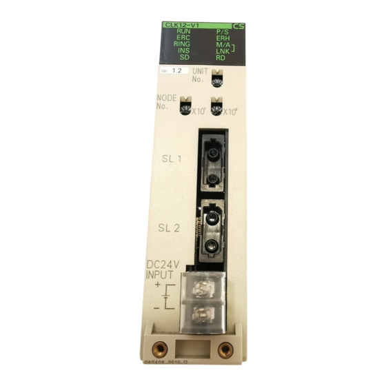
Section 3-1 Component Names and Functions Component Names and Functions This section describes the names and functions of the Controller Link Unit components. This section also describes the operation of the indicators. 3-1-1 CS-series Optical Ring Controller Link Units (H-PCF Cable) CS1W-CLK13 CS1W-CLK12-V1 (Refer to p. - Page 72 Section 3-1 Component Names and Functions Meanings of LED Indicators Name Color Status Meaning Green Unit operating normally or, if Communica- (operating) tions Units are used in duplex operation, Unit operating normally in active mode. Flashing If Communications Units are used in duplex operation, Unit operating normally in standby mode.
- Page 73 Section 3-1 Component Names and Functions Dimensions (Unit: mm)
-
Page 74: Cvm1 And Cv-Series Optical Ring Controller Link Units (H-Pcf Cable)
Section 3-1 Component Names and Functions 3-1-2 CVM1 and CV-series Optical Ring Controller Link Units (H-PCF Cable) CVM1-CLK12 (Refer to p. 49, 236.) Indicators LED indicators that display the Unit and Network status. (Refer to p. 81.) Unit number switches Two rotary switches. - Page 75 Section 3-1 Component Names and Functions Meanings of LED Indicators Name Color Status Meaning Green Unit operating normally. (operating) Not lit Unit error. Green Backup power is being supplied. (power supply) Not lit Backup power is not being supplied. ERC (communica- Communications error, node address setting tions error) error (same address set twice), or hardware...
- Page 76 Section 3-1 Component Names and Functions Dimensions (Unit: mm)
-
Page 77: Cs-Series Optical Ring Controller Link Units (Gi Cable)
Section 3-1 Component Names and Functions 3-1-3 CS-series Optical Ring Controller Link Units (GI Cable) CS1W-CLK53 CS1W-CLK52-V1 (Refer to p. 49, 236.) Indicators LED indicators that display the Unit and network status. (Refer to p. 77.) Unit number switch One rotary switch. The unit number is set in single-digit hexadecimal. - Page 78 Section 3-1 Component Names and Functions Meanings of LED Indicators Name Color Status Meaning Green Unit operating normally or, if Communica- (operating) tions Units are used in duplex operation, Unit operating normally in active mode. Flashing If Communications Units are used in duplex operation, Unit operating normally in standby mode.
- Page 79 Section 3-1 Component Names and Functions Dimensions (Unit: mm) UNIT NODE (13.5) Note Dimensions given in parentheses are for the CS1W-CLK53 and include the terminal cover.
-
Page 80: Cvm1 And Cv-Series Optical Ring Controller Link Units (Gi Cable)
Section 3-1 Component Names and Functions 3-1-4 CVM1 and CV-series Optical Ring Controller Link Units (GI Cable) CVM1-CLK52 (Refer to p. 49, 236.) Indicators LED indicators that display the Unit and Network status. (Refer to p. 81.) Unit number switches Two rotary switches. - Page 81 Section 3-1 Component Names and Functions Name Color Status Meaning Yellow Data Data links not active in the network. (data link mode) links active in the net- work. Manual Note: (See M/A is always not lit when data note.) links are not active in the network. Not lit Auto- matic...
-
Page 82: Installation
Section 3-2 Installation Dimensions (Unit: mm) 34.5 Installation The Controller Link Unit is mounted onto a CPU Backplane or Expansion CPU Backplane for use. For detailed information on PLC installation procedures, refer to the installation guide for the applicable PLC. Note 1. -
Page 83: Cvm1 And Cv-Series Plcs
Section 3-2 Installation 3-2-1 CVM1 and CV-series PLCs Up to four Controller Link Units for CVM1 and CV-series PLCs can be installed in a CPU Backplane or a Expansion CPU Rack. Controller Link Units cannot be installed on an Expansion I/O Rack, a SYSMAC BUS Slave Rack, or a SYSMAC BUS/2 Slave Rack. -
Page 84: Cs1 And Cs1-H Plcs
Section 3-2 Installation 3-2-2 CS1 and CS1-H PLCs Up to a total of eight Controller Link Units with unit version 1.2 or later (wired and optical) for CS-series PLCs (or up to four pre-Ver. 1.2 Controller Link Units) can be installed in a CPU Backplane or an Expansion CPU Rack. Con- troller Link Units cannot be installed on a C200H Expansion I/O Rack or a SYSMAC BUS Slave Rack. -
Page 85: Cs1D Plcs
Section 3-2 Installation 3-2-3 CS1D PLCs Up to 3 pairs (i.e., active Unit and standby Unit) of CS-series Controller Link Units used in duplex operation and one CS-series Controller Link Unit not used in duplex operation can be mounted to a CS1D Duplex Backplane or an Expansion Backplane supporting online replacement. -
Page 86: Optical Wiring
Section 3-3 Optical Wiring Optical Wiring 3-3-1 Optical Fiber Cable Connections for H-PCF Cable Optical Bus and Optical All of the nodes in the network are connected in a line (daisy-chain configura- Ring Systems (Token-bus tion) with H-PCF Optical Fiber Cable. Mode) The nodes can be connected in any order, but be sure to begin with the upper connector (SL1) of the highest node in the network and connect to the lower... - Page 87 Section 3-3 Optical Wiring ← Higher Lower → See 1-2-6 Devices Required for Connection for details on available H-PCF Optical Fiber Cables. Note 1. Always use the specified Optical Fiber Cables. 2. The maximum distance between nodes depends on how the cable is pro- cessed.
-
Page 88: Optical Fiber Cable Connections For Gi Cable
Section 3-3 Optical Wiring 3. The maximum distance between nodes depends on how the cable is pro- cessed. For details, refer to the applicable Optical Fiber Cable (H-PCF) manual. 4. There are no special restrictions that apply to the distance between stand- by Controller Link Units and higher or lower Controller Link Units. - Page 89 Section 3-3 Optical Wiring 3. The maximum distance between nodes depends on the type of GI cable (core diameter) that is being used. 62.5/125 µ m cable: Max. distance between nodes = 2 km 50/125 µ m cable: Max. distance between nodes = 1 km 4.
-
Page 90: Backup Power Supply Wiring
Section 3-3 Optical Wiring Although there is no fixed order in which the nodes must be connected, in order to minimize the effect on communications time in the event of a discon- nection, it is recommended that they be connected in node address order (node 1 →... -
Page 91: Connecting Optical Fiber Cable To Connectors For H-Pcf Cable
Section 3-3 Optical Wiring 2. When wiring is complete, remove the label to avoid overheating. 3. Use a power supply that is not connected to PLC operation, as in the case of the node bypass function, for the backup power supply so that when the power to the PLC is turned OFF, the backup power supply will continue. - Page 92 Section 3-3 Optical Wiring Example: Connections for Duplex Operation of Communications Units Mounting bracket Tension member Terminal Higher side Lower side • Insert the connectors completely and always check that the connectors are locked before starting operation. • If a connector becomes disconnected while in token-bus mode, the node will be unable to communicate with other nodes in that part of the net- work.
-
Page 93: Connecting Optical Fiber Cable To Connectors For Gi Cable
Section 3-3 Optical Wiring • Do not bend the cable too sharply. The minimum radius for bends is 10 cm. • To prevent the Optical Fiber Cable from being pulled too forcefully, always use the cable securing bracket and provide space below the Unit as shown in the following diagram. - Page 94 Optical Wiring Section 3-3 2. Attach the clamp to the mounting bracket so that it clamps the cable(s). Two cables can be attached at the same time. 1. Screw the mounting bracket to the Unit. Mounting bracket 2. Attach the clamp to the mounting bracket so that the cable(s) are clamped.
- Page 95 Optical Wiring Section 3-3 Unit's optical Cable connector connector Slot Press and turn the metal fitting on the cable connector until it locks. Align the tab in the cable connector with the slot in the Unit's connector and fully insert the cable connector. Note To remove the connector, just reverse the steps shown in the dia- gram above.
-
Page 96: Connecting Backup Power Supply Cables
Section 3-3 Optical Wiring 3-3-6 Connecting Backup Power Supply Cables Attach crimp terminals to the power supply cable when connecting the backup power supply to the Controller Link Unit. Backup power 24 VDC supply − H-PCF cable GI cable (CS1W-CLK13, (CS1W-CLK53, CS1W-CLK12-V1, or CS1W-CLK52-V1, or... - Page 97 Optical Wiring Section 3-3...
- Page 98 SECTION 4 Preparations for Communications This section describes the settings required for starting communications. These basic settings are required both for data links and the message service. Carry out the settings described here before turning ON power to the Controller Link Unit.
-
Page 99: Cs-Series Optical Ring Controller Link Units
Section 4-1 CS-series Optical Ring Controller Link Units CS-series Optical Ring Controller Link Units Before starting communications, the following settings are required for an Optical Ring Controller Link Unit (H-PCF cable or GI cable) used with a CS- series PLC. Item Setting location Page... -
Page 100: Setting The Unit Number
CS-series Optical Ring Controller Link Units Section 4-1 Transmission Path Format Setting (Software Switch) Setting range Nodes Token-ring mode All nodes in the Network Token-bus mode Software switch (DM30000 + 100 x unit number) 0: Always set to 0. Transmission path setting -: Other settings. -
Page 101: Setting The Node Addresses
Section 4-1 CS-series Optical Ring Controller Link Units 4-1-3 Setting the Node Addresses Set the node addresses of each Unit on the network using the rotary switches on the front of the Unit. When using Controller Link Units in duplex operation, set the same node address for each active/standby pair of Units. -
Page 102: Setting The Transmission Path Format
Section 4-2 CVM1 and CV-series Optical Ring Controller Link Units 4-1-4 Setting the Transmission Path Format The transmission path format is set by a software switch allocated in the CPU Unit’s DM parameter area. The same setting must be made for all nodes in the network. -
Page 103: Overview
Section 4-2 CVM1 and CV-series Optical Ring Controller Link Units Item Switch Page Node address Node address switch Transmission path format Software switch 4-2-1 Overview Unit Number setting Node Address setting H-PCF cable GI cable Unit Number Setting range Nodes 00 to 15 (default is 00) All nodes in the Network Node Address... -
Page 104: Setting The Unit Number
Section 4-2 CVM1 and CV-series Optical Ring Controller Link Units Transmission Path Format Setting (Software Switch) Setting range Nodes Token-ring mode All nodes in the Network Token-bus mode Software switch (DM30000 + 100 x unit number) 0: Always set to 0. Transmission path setting -: Other settings. -
Page 105: Setting The Node Address
Section 4-2 CVM1 and CV-series Optical Ring Controller Link Units 4-2-3 Setting the Node Address Set the node address of each Unit in the network using the rotary switches on the front of the Unit. The node address is used to identify each node in the Network. -
Page 106: Creating I/O Tables
Section 4-2 CVM1 and CV-series Optical Ring Controller Link Units Transmission Path Setting contents Token-ring mode Token-bus mode Note 1. Set the transmission path format before connecting the Controller Link communications cable. 2. Make the same setting for all the nodes in the network. The network will not operate normally if the settings are different. - Page 107 Section 4-2 CVM1 and CV-series Optical Ring Controller Link Units...
- Page 108 SECTION 5 Data Links This section describes how to use data links in a Controller Link Network. Refer to Section 2 Basic Procedures for an outline of data link application. What Are Data Links? ......... . 5-1-1 Data Link Specifications .
-
Page 109: What Are Data Links
Section 5-1 What Are Data Links? What Are Data Links? Data links automatically exchange data in the preset areas between nodes (PLCs and/or computers) on one network. Data links can be freely created for CS-series, CVM1, and CV-series PLCs, and IBM PC/AT or compatible com- puters (in token-bus mode only). - Page 110 Section 5-1 What Are Data Links? Manually Setting Data Links Example 1: The order of send and receive Example 2: Some nodes can send data without receiving data. nodes is free. Area 1 Area 1 Send only Area 2 Area 2 Example 3: Some nodes can receive Example 4: A node can receive only a...
- Page 111 Section 5-1 What Are Data Links? Automatically Setting Data Links with Equality Layout Example Node#1 Node#2 Node#3 Area 1 (Bit areas) Area 2 (Data Memory) Automatic setting can be used to create simple data links. • Using a Programming Device (such as a Programming Console), set the automatic data link mode in the DM parameter area of the startup node.
- Page 112 Section 5-1 What Are Data Links? Automatically Setting Data This method is used to simplify the setting of 1:N allocation data links between Links with 1:N Allocations master and slave nodes. Node 1 Node 2 Node 3 Node 4 Area 1 Area 2 •...
- Page 113 Section 5-1 What Are Data Links? Lot Number notation: The first two digits refer to the year (last two digits of years from 2000 onwards), and the following two digits indicate the month (01 to 12, for January to December, respectively). (The last 7 digits are not relevant.) 2.
- Page 114 Section 5-1 What Are Data Links? Offsetting Image #1 Data #1 Data I only need this. I need all of it. Application Example of Using Offsets In the following example, the send data from node 1 is split into three parts and each part is received by a different node, i.e., each of the other nodes receives only part of the send data from node 1.
-
Page 115: Data Link Specifications
Section 5-1 What Are Data Links? 5-1-1 Data Link Specifications Item Description Number of 62 max., 2 min. (See note 1 and 2.) data link nodes Number of Number of send words per node (total for area 1 and 2): data link 4,000 words max. -
Page 116: Differences Between Manual And Automatic Setting
Section 5-1 What Are Data Links? 5-1-2 Differences Between Manual and Automatic Setting Item Manual setting Automatic setting Determination of Determined by setting data link Determined by the data link nodes to be in a tables. parameters set in the data link data link startup node (the node used to start the data links). -
Page 117: Setting Data Links
Section 5-2 Setting Data Links Setting Data Links 5-2-1 Selecting Manual or Automatic Setting Specify either the manual or automatic data link mode in the following DM parameter area of the PLC’s CPU Unit of the startup node, using a PLC Pro- gramming Device. -
Page 118: Manual Setting
Section 5-2 Setting Data Links 5-2-2 Manual Setting Transfer the data link tables that were created on the Controller Link Support Software (Ver. 2.00 or later) or CX-Net (in CX-Programmer) to the Controller Link Unit or the Controller Link Support Board (for IBM PC/AT or compatible computers). - Page 119 Section 5-2 Setting Data Links Note 1. The following three methods can be used to start data links. (See p. 127.) • Using a software switch • Using the Controller Link Support Software or CX-Net (in CX-Program- mer) • Using an FINS command 2.
- Page 120 Section 5-2 Setting Data Links Setting item Setting range Area 1 Data link CIO Area: CIO 000 to CIO 6143 start word LR Area: LR 00 to LR 199 (*) DM Area: DM 0000 to DM 32767 EM Area: Banks 00 to 12, EM 0000 to EM 32767 Unit Ver.
- Page 121 Section 5-2 Setting Data Links 2. The following values must be satisfied for each node for the data link Area 1 and Area 2 so that the final word in the data link does not go beyond the last word in the PLC memory area. (Data link start word –...
- Page 122 Section 5-2 Setting Data Links Setting item Setting range Area 1 Data link CIO Area: CIO 0000 to CIO 2555 start word LR Area: LR 000 to LR 199 (*) DM Area: DM 0000 to DM 8191 (CV500/CVM1-CPU01) DM 0000 to DM 24575 (Other CPU Units) EM Area: Banks 00 to 07, EM 0000 to EM 32765 (EM must be installed) The same area cannot be set for both Area 1 and Area 2.
-
Page 123: Manual Setting Examples
Section 5-2 Setting Data Links (Data link start word – 1) + (Total number of send/receive words in area) ≤ 2555 (CIO Area) 199 (LR Area) 8191 (DM Area for CV500/CVM1-CPU01) 24575 (DM Area for other CPU Units) 32765 (EM Area) 3. - Page 124 Section 5-2 Setting Data Links SAMPLE1.CLK: Same Allocation to All Nodes Data Link Area Structure CS1G-CPU42 CS1G-CPU42 CS1G-CPU42 CS1G-CPU42 Node 1 Node 2 Node 3 Node 4 Data Link Areas Area 1 LR000 LR010 LR020 LR030 LR049 Area 2 D00000 D00200 D00300 D00400...
- Page 125 Section 5-2 Setting Data Links Checking the Data Link Tables Transferring the Data Link Tables Saving the Data Link Tables SAMPLE2.CLK: Different Allocations to Each Node Data links can be created so that one node does not receive from all other nodes or so that some nodes do not send or receive any data at all.
- Page 126 Section 5-2 Setting Data Links Data Link Area Structure CS1G-CPU42 CS1G-CPU42 CVM1-CPU21 CVM1-CPU21 Node 1 Node 2 Node 3 Node 4 Data Link Areas Area 1 LR000 LR010 01000 01005 LR010 LR020 01015 01020 LR030 LR039 01035 01039 LR049 01054 Area 2 D00000 E0_00020...
- Page 127 Section 5-2 Setting Data Links Data Link Tables SAMPLE3.CLK: Creating Data Link Groups within a Network Data links consisting of multiple groups within a single network can be created by setting data link tables. Send and receive areas are created for only the nodes in each group, as shown below.
- Page 128 Section 5-2 Setting Data Links Device Information Setting Data Link Tables...
- Page 129 Section 5-2 Setting Data Links SAMPLE4.CLK: Receiving Only Part of Send Data and Offsets Only Area 2 is used in this example. Note A Controller Link Support Board is used in this example. The Support Board does not have memory areas. The area settings are ignored and byte addresses are used.
-
Page 130: Automatic Setting: Select All
Section 5-2 Setting Data Links Data Link Tables 5-2-4 Automatic Setting: Select All Data links can be automatically created by setting values in the DM parameter area of the PLC’s CPU Unit of the startup node. The settings are made using a Programming Console or the CX-Programmer. - Page 131 Section 5-2 Setting Data Links CS-series Startup Node Automatic setting for the CS Series can be performed using either equality layout (previous pattern), whereby each node is allocated the same link area size, or 1:N allocations, which allows an individually set exchange of data between the master node and slave nodes.
- Page 132 Section 5-2 Setting Data Links Automatic Setting, 1:N This method is used to simplify the setting of 1:N allocation data links between Allocations master and slave nodes. Node 1 Node 2 Node 3 Node 4 Area 1 Area 2 • There are three types of 1:N allocations. •...
- Page 133 Section 5-2 Setting Data Links Lot number notation: The first two digits refer to the year (last two digits of years from 2000 onwards), and the following two digits indicate the month (01 to 12, for January to December, respectively). (The last 7 digits are not relevant.) 2.
- Page 134 Setting Data Links Section 5-2 Item Setting range Area 1 type Set the area for Area 1 in BCD. CIO Area: 80 Hex LR Area: 86 Hex Area 1 not used: 00 Hex Number of send words Set the number of words in BCD between 0 and per node of Area 1 1,000.
- Page 135 Setting Data Links Section 5-2 (e) The startup node must be set as a participating node of the data links. If not, the data links will not start. 1:N Allocations, Common Type (7) Participating nodes Master node Slave nodes Area 1 (1) Area and start word (2) Number of send words for master node (3) Number of send words per slave node...
- Page 136 Section 5-2 Setting Data Links − N+12 1:N allocation type (Set value 0001 = Common type) N+13 Start word for Area 1 (bit-access area, BCD) N+14 Area 1 type N+15 Area 1 number of send words for master node (BCD) N+16 Area 1 number of send words per slave node (BCD) N+17...
- Page 137 Setting Data Links Section 5-2 Item Setting range Area 1 number of send Set the number of words in BCD between 0 and 1,000. words per slave node The total number of send words per slave node of Area 1 and Area 2 must not exceed 1,000.
- Page 138 Section 5-2 Setting Data Links 5. The total number of words in data link send and receive areas must not ex- ceed 20,000 per node when using Controller Link Units with unit Ver. 1.2 or later, or 12,000 words per node if using pre-Ver. 1.2 Controller Link Units.
- Page 139 Section 5-2 Setting Data Links 1:N Allocations, 1 to 1 Type (5) Participating nodes Master node Slave nodes (1) Area and start word (2) Number of common send words for the master node (3) Number of individual send words for the master node (Same as (3)) (Same as (3)) (4) Number of send words for the slave nodes...
- Page 140 Setting Data Links Section 5-2 − N+12 1:N allocation type setting (Set value 0002 = 1 to 1 type) N+13 Rightmost 4 digits of start word (BCD) N+14 Area 1 type Leftmost digit of area start word (BCD) N+15 Number of common send words for master node (BCD) N+16 Number of individual send words for master node (BCD) N+17...
- Page 141 Section 5-2 Setting Data Links Item Setting range Number of common send Set the number of words in BCD between 0 and 1,000. words for the master The number of common send words per master node node added to the number of individual send words per master node multiplied by the number of slave nodes participat- ing in the data links must not exceed 1,000.
- Page 142 Section 5-2 Setting Data Links (Area start word - 1) + (Total number of send and receive words of master node.*) ≤ 6143 (when using the CIO or AR Area) 199 (when using LR Area) 32767 (when using DM or EM Area) *:Total number of send and receive words in master node = Number of common send words in master node + Number of individual send words in master node ×...
- Page 143 Section 5-2 Setting Data Links • The master node receives all data sent by the slaves. The data sizes are fixed for all nodes. • Each slave nodes receives data from the previous node and then sends data to the next node. Data is thus passed in ascending order of the nodes that are participating in the data link.
- Page 144 Setting Data Links Section 5-2 Item Setting range Area start word Set the word address in BCD. CIO Area: 0 to 6143 LR Area: LR 000 to LR 199 (1000 to 1199) (*) DM Area: DM 0 to 32767 EM Area: Banks 0 to 12 EM 0 to 32767 *: When a word between LR 000 and LR 199 is specified, the data link area will be allocated between words 1000 and 1199 in the CIO Area.
- Page 145 Setting Data Links Section 5-2 Total number of words in the data link send and receive areas of master node = Number of common send words in master node + Number of individual send words in each node × Number of nodes par- ticipating in data links (including both master nodes and slave nodes) 5.
- Page 146 Section 5-2 Setting Data Links CVM1 or CV-series Startup Node Set the following DM parameter area settings in the PLC that is the startup node. DM 2000 + 100 Controller Link Unit number 15 14 13 12 11 10 9 Word N 0: Always specify 0.
- Page 147 Setting Data Links Section 5-2 Item Setting range Area 2 type Set the area for Area 2 in BCD. DM Area: 82 Hex EM Area: Banks 00 to 07: 90 to 97 Hex Area 2 not used: 00 Hex Number of send words Set the number of words in BCD between 0 and 1,000.
-
Page 148: Automatic Setting Example
Section 5-2 Setting Data Links 2. The following limitations apply when Optical Bus (CLK11) and Optical Ring (H-PCF cable) (CLK12, CLK12-V1, or CLK13) Controller Link Units are used in combination. • The data that can be received by the Optical Bus Controller Link Units is limited to node addresses 1 to 32, and the data link status that is re- flected is also limited to these node addresses. - Page 149 Section 5-2 Setting Data Links Data Link Areas Created Node #1 Node #2 Node #3 LR 0 LR 10 Area 1 LR 20 DM1000 DM1200 Area 2 DM1400 DM Parameter Setting When automatic data link creation with common type 1:N allocations is used, Example for 1:N the DM parameters area of the startup node is set as follows: Allocation, Common Type...
-
Page 150: Starting And Stopping Data Links
Starting and Stopping Data Links Section 5-3 Data Link Area Node 1 Node 2 Node 3 Node 4 CIO 100 Area 1 CIO 130 CIO 150 CIO 170 DM 1000 Area 2 DM 1400 DM 1600 DM 1800 Note 1. Node 1 is the master node. 2. -
Page 151: Using A Programming Device Or The User Program
Section 5-3 Starting and Stopping Data Links 2. In CS1D Systems with Controller Link Units used in duplex operation, set the duplex node as a startup node for data links (Data Link Start/Stop Bit in the CS1D System CPU Unit is turned ON). If the duplex node is not set to be a startup node for data links (Data Link Start/Stop Bit in the CS1D System CPU Unit is OFF), and the relevant node is operating as a polling node, the network's data links may stop if an ACT/STB (active/standby) -
Page 152: Using The Controller Link Support Software (Ver. 2.00 Or Later) And Cx-Programmer
Section 5-3 Starting and Stopping Data Links startup node for data links (Data Link Start/Stop Bit in the CS1D System CPU Unit is OFF), and the relevant node is operating as a polling node, the net- work's data links may stop if an ACT/STB (active/standby) switchover error occurs. -
Page 153: Checking Data Link Status
Section 5-4 Checking Data Link Status Checking Data Link Status There are two methods for checking the status of active data links: • Check the LED indicators on the front of the Units. • Check the data link status area. When using Controller Link Units in duplex operation, check the data link operating status at the active Controller Link Unit. - Page 154 Section 5-4 Checking Data Link Status The number of words used for data link status, and the information that is reflected, depends on the setting (8-bit or 4-bit format) for the data link status storage format specification in the DM parameters area, as shown in the fol- lowing diagram.
- Page 155 Section 5-4 Checking Data Link Status 4. Even if an offset error occurs, the data link will operate and the node will participate in the data links. In the node where the offset error occurred, however, all receive area words will be cleared to 0. 5.
- Page 156 Section 5-4 Checking Data Link Status 4. When the data link status area is set in the CIO or LR Area, the data link status will be instantaneously set to 0 when the mode of the PLC’s CPU Unit is changed. The flags in the data link status operate as follows: Name Function...
-
Page 157: Data Link Status Storage Format
Section 5-4 Checking Data Link Status Data link PLC and First data link Setting range Default status mode operating level status word CIO 1500 + 25 × N + 7 to 22 Manual CS-series PLC Specify in the data 16 words in the following link tables ranges CIO:... -
Page 158: Checking By Manipulating Bit/Word Status
Section 5-4 Checking Data Link Status 5-4-4 Checking by Manipulating Bit/Word Status After you have confirmed that the data link function is operating normally, check to see whether or not the data link is operating as intended, i.e., check to see if the desired bits/words data is being transferred to the intended words at other nodes. - Page 159 Section 5-4 Checking Data Link Status Note The network uses the data link storage format setting that is set in the startup node. Therefore, if multiple nodes are set as startup nodes, make sure that they all have the same settings. If the settings are different in each startup node, the data link storage format setting used will depend on the startup node.
- Page 160 Section 5-4 Checking Data Link Status Local Node Data Node A Link Participation Node A Communications Flag Participation Flag Error Flag Node A Error output Node B Node B Communications Participation Flag Error Flag Node B Error output Node C Node C Communications Participation Flag...
- Page 161 Section 5-4 Checking Data Link Status The parts of the ladder program that use the data link area for the Data Link Normal Additional part relevant node are processed only Operation Flag when the corresponding Normal Operation Flag is ON. Data Link Normal Operation Flag Data Link Normal Operation Flags can be created using the programming...
- Page 162 Section 5-4 Checking Data Link Status Example of Programming for Node 1 to Handle Communications Errors at Node 2 Node 2 Data Link Normal Operation Flag BSET 0000 is written continuously in node 2's area (D00100 to # 0 0 0 0 D00120) until node 2's flag D00100 turns ON.
- Page 163 Section 5-4 Checking Data Link Status...
- Page 164 SECTION 6 Message Service This section explains how to use the message service provided by a Controller Link Unit. It also explains the FINS commands and responses supported by Controller Link Units and those supported by CS-series, CVM1 and CV-series PLCs.
-
Page 165: Introduction
Introduction Section 6-1 Introduction A message service is a command/response system used for data transmis- sion between nodes on a network, i.e., PLC to PLC, PLC to computer, and computer to PLC). The message service can also be used to control opera- tions, such as mode changes. -
Page 166: Send And Recv
Section 6-1 Introduction 6-1-1 SEND and RECV I/O memory data from other nodes can be read or written by simply using the program in the CPU Unit of a CS-series, CVM1, or CV-series PLC to execute SEND and RECV. CS-series PLCs SEND SEND transmits “n”... - Page 167 Introduction Section 6-1 3. If the total number of data link words is increased, the communications cy- cle time will be increased. This may cause timeout errors to occur when waiting for the response. In that case, lengthen the response monitor time (control data word C+4).
- Page 168 Section 6-1 Introduction 3. If the total number of data link words is increased, the communications cy- cle time will be increased. This may cause timeout errors to occur when waiting for the response. In that case, lengthen the response monitor time (control data word C+4).
- Page 169 Section 6-1 Introduction RECV RECV receives “m” words beginning with S (the beginning word for data transmission at the remote node, M) to the words beginning with D (the begin- ning word for data reception at the local node). Local node Remote (source) node M "m"...
-
Page 170: Cmnd
Introduction Section 6-1 6-1-2 CMND The CMND instruction can be executed in the user program in a CS-series, CVM1, or CV-series PLC to perform operations such as reading and writing memory data from and to other nodes, reading status information, and chang- ing the operating mode. - Page 171 Section 6-1 Introduction resend processing at the node where instructions are issued. With the SEND, RECV, and CMND instructions, resend processing is performed automatically once the number of retries has been set, so be sure to specify a number other than “0”...
- Page 172 Section 6-1 Introduction 2. With the message service, there is no guarantee that a message to a re- mote node will reach its destination. It is always possible that the message may be lost in transit due to noise or some other condition. When using the message service, it is advisable to prevent this situation from occurring by performing resend processing at the node where instructions are issued.
-
Page 173: Send/Receive Data Areas
Section 6-1 Introduction Type of command Code CVM1/ Error data ERROR CLEAR 2101 ERROR LOG READ 2102 ERROR LOG CLEAR 2103 File Memory FILE NAME READ 2201 SINGLE FILE READ 2202 SINGLE FILE WRITE 2203 MEMORY CARD FOR- 2204 FILE DELETE 2205 VOLUME LABEL CRE- 2206... - Page 174 Section 6-1 Introduction CVM1 and CV-series PLCs Area Range CV500, CVM1-CPU01 CV1000/2000, CVM1-CPU11/21 CIO Area 0000 to 2555 CPU Bus Link Area G000 to G255 (See note 1.) Auxiliary Area A000 to A511 (See note 2.) Timer Area T000 to T511 T000 T1023 Counter Area C000 to C511...
-
Page 175: Selecting Communications Instructions
Section 6-2 Selecting Communications Instructions Selecting Communications Instructions Do you want to easily read from Use SEND and RECV. or write to the I/O memory area? Do you want to intermittently read Use CMND. from a memory area? Aside from memory areas, do you want to write the following kinds of data? PLC internal clock... -
Page 176: Message Service Operations
Section 6-2 Selecting Communications Instructions 6-2-1 Message Service Operations Instruction Local Remote node Communications Data Broadcasting Network node contents length connections Computer CVM1, or CVM1, or SEND and Yes (See Read to and write 990 words SEND only (no Yes (up to three lev- RECV note.) from all I/O memory... -
Page 177: Using The Message Service
Section 6-3 Using the Message Service Using the Message Service With SEND, RECV, and CMND, the Network Instruction Enabled Flag and Network Instruction Error Flag are generally written into the program as input conditions, as shown below. Only one instruction can be executed at a time for any given communications port. - Page 178 Section 6-3 Using the Message Service CVM1 and CV-series PLCs Name Address Contents Word Network A502 Port number corresponds 0: Execution not enabled (executing) Instruction to bit number, i.e., port 0: 1: Execution enabled (not executing) Enabled Flag bit 00, port 1, bit 00, etc. Network A502 Port number corresponds...
- Page 179 Section 6-3 Using the Message Service Communications Instruction Response Codes The status after a communications instruction has been executed is reflected in the words shown in the following table. During instruction execution, it becomes “00” or “0000,” and it is reflected here after the execution has been completed.
- Page 180 Section 6-3 Using the Message Service PLC Programming Examples CS-series PLCs Execution condition 000000 A20207 120002 The transmission program will run when CIO 00000 KEEP 120000 turns ON, provided that the Network Instruction En- abled Flag is ON and the RECV instruction has not (See note 1.) been executed.
- Page 181 Section 6-3 Using the Message Service (Continued from the previous page) Execution condition The reception program will run when CIO 00001 turns ON, provided that the Network Instruction En- 000001 A20207 120000 KEEP abled Flag is ON and the SEND instruction has not 120002 been executed.
- Page 182 Section 6-3 Using the Message Service CVM1 and CV-series PLCs The transmission program will run when I000000 is ON, I0000 A502 1200 provided that the Network Instruction Enabled Flag for (011) port 7 is ON and the RECV instruction has not been KEEP 120000H executed.
-
Page 183: Fins Commands And Responses
FINS Communications Service The FINS communications service is a communications protocol developed by OMRON for FA control devices. It can be used for reading from and writing to PLC memory, or for controlling various operations, without having to create a user’s program at the PLC. The FINS communications service has its own... - Page 184 Section 6-4 FINS Commands and Responses 1 byte 1 byte Word @CMND Command 1 byte 1 byte Word Response 2 bytes 2,000 bytes max. FINS header Controller CPU Unit Link Unit Automatically pre- Command code Text Computer pared and added. CS, CVM1, CV-series, or CQM1H-...
-
Page 185: Applicable Units For Fins Commands
Section 6-5 Commands and Responses for Controller Link Units MRES Execution result MRES Execution result Parameter error Service interrupted by abort Read not possible 6-4-3 Applicable Units for FINS Commands The parameters used with FINS commands and responses depend on the Unit to which the command is being sent. -
Page 186: Data Link Start
Section 6-5 Commands and Responses for Controller Link Units Note Command codes 0604, 0605, and 0606 are valid only for Optical Ring Con- troller Link Units in token-ring mode. They cannot be used in token-bus mode or with any other Controller Link Units. 6-5-2 DATA LINK START Starts the Controller Link Network data links. -
Page 187: Controller Status Read
Section 6-5 Commands and Responses for Controller Link Units Response Block 20 bytes 20 bytes Model Version Command Response Wired/ Node Unit Network code code Optical address address address Parameters Model number, version (response): The Controller Link Unit’s model num- ber and version are returned as shown below, each 20 characters in ASCII code. - Page 188 Section 6-5 Commands and Responses for Controller Link Units Response Block 8 bytes Command Response code Count 8 Active node list Status 1 Status 3 Status 5 Count 1 code Operating status Status 2 Status 4 Status 6 Total 6 bytes Total 8 bytes Parameters Operating status (response): The operating status of the data links as fol-...
-
Page 189: Network Status Read
Section 6-5 Commands and Responses for Controller Link Units A PLC system setting errors occurs if the Controller Link Unit is not properly recognized by a CVM1 or CV-series PLC. A PLC model error occurs if a C200HX/HG/HE Controller Link Unit is mounted to another type of PLC. - Page 190 Section 6-5 Commands and Responses for Controller Link Units Participation Status of Individual Nodes Byte 1 Node #1 Reserved Byte 2 Node #3 Node #2 Node #5 Byte 3 Node #4 0: Not part of network 1: Part of network 0: Normal disconnection (Applicable only for Byte 17...
-
Page 191: Data Link Status Read
Section 6-5 Commands and Responses for Controller Link Units Byte 1 Number of error occurrences for node #1 Byte 2 Number of error occurrences for node #2 Byte 3 Number of error occurrences for node #3 Byte 32 Number of error occurrences for node #32 Number of error occurrences for node #33 Byte 33 Byte 62... -
Page 192: Connection Data Read
Section 6-5 Commands and Responses for Controller Link Units Status (response): The data link status of each mode is returned as shown in the following diagram. It is the same as the data link status in the PLC. (Refer to page 130.) Data link status for each node 7 6 5 4 3 2 1 0 Byte 1... - Page 193 Section 6-5 Commands and Responses for Controller Link Units Parameters Beginning node to read (command): With the local node as the starting point (0), specify the node for beginning reading, with a 1-byte hexadecimal value (2 digits) counted as 1, 2, etc., in the descending (SL2) direction. Set the value from 00 to 3E Hex (decimal: 0 to 62).
-
Page 194: Network Disconnect Data Read
Commands and Responses for Controller Link Units Section 6-5 6-5-9 NETWORK DISCONNECT DATA READ Reads the disconnection status of the Controller Link Unit. This command can only be used in token-ring mode, for Optical Ring Controller Link Units (H- PCF cable or GI cable). Command Block Command format... - Page 195 Commands and Responses for Controller Link Units Section 6-5 The data for the two modes is returned by “disconnect detect node data 1” and “disconnect detect node data 2.” Time of beginning disconnection data recording: The time that the record- ing of the disconnection data was begun is returned in one byte (2 digits) BCD for each of the following in order: minute, second, day, hour, year, month.
-
Page 196: Network Disconnect Data Clear
Section 6-5 Commands and Responses for Controller Link Units Aside from the disconnect detection flag parameter, disconnection information is not cleared even when communications are restored. (The present discon- nection status is always reflected in the disconnect detection flag parameter.) The disconnect detection node data 1 and 2 parameters, however, are over- written by new disconnection data. -
Page 197: Echoback Test
Commands and Responses for Controller Link Units Section 6-5 6-5-11 ECHOBACK TEST Executes an echoback communications test between specified nodes. Command Block 1,998 bytes max. Command Test data code Response Block 1,998 bytes max. Command Response Test data code code Parameters Test data (command, response): For the command, up to 1,998 bytes of data can be specified to be sent to a specified node. -
Page 198: Broadcast Test Data Send
Section 6-5 Commands and Responses for Controller Link Units 6-5-13 BROADCAST TEST DATA SEND Broadcasts test data to all nodes in a specified network. Command Block 2,000 bytes max. Command Test data code There is no response to this command. The control data must be set as follows when this command is issued: Remote node address: FF (Hex) (for broadcasting the data) -
Page 199: Error Log Clear
Section 6-5 Commands and Responses for Controller Link Units Model CS1W-CLK13 CS1W-CLK12(-V1) Parameter number CS1W-CLK53 CS1W-CLK52(-V1) Response Max. no. of 0040 hex, fixed 0027 hex, fixed stored (Decimal: 64) (Decimal: 39) records 64 records max. 39 records max. No. of stored 0001 to 0040 hex 0001 to 0027 hex records... -
Page 200: Response Codes
Response Codes Section 6-6 Response Codes This section describes the response codes returned with responses to FINS commands. Response codes can be used to confirm normal completion of command execution or to troubleshoot problems when commands fail. For fur- ther troubleshooting information, refer to SECTION 9 Troubleshooting and Maintenance of this manual and to the operation manuals for specific Units or Systems. - Page 201 Section 6-6 Response Codes Error node address: Controller Link:01 to 3E (Hex) (1 to 62 in decimal) (*1) Ethernet:01 to 7E (Hex) (1 to 126 in decimal) SYSMAC NET:01 to 7E (Hex) (1 to 126 in decimal) SYSMAC LINK:01 to 3E (Hex) (1 to 62 in decimal) *1 This is 01 to 20 Hex (1 to 32) for Wired or Optical Bus (CLK11) Controller Link Units.
-
Page 202: Response Codes And Troubleshooting
Section 6-6 Response Codes MRES - - SRES PS: Power Supply Unit CPU: CPU Unit Transmission CLK: Controller Link Unit Response SNT: SYSMAC NET Link Unit If an error occurs, check the MRES and SRES codes for the node in question, and correct the problem. - Page 203 Section 6-6 Response Codes Main code Sub- Probable cause Remedy code 02: Remote node error Remote node not part of Network Add to Network. No node with the specified node Check the remote node’s node address. address Third node not part of Network Check the third node’s node address.
- Page 204 Section 6-6 Response Codes Main code Sub- Probable cause Remedy code 10: Command format The command is longer than the max. Check the command format of the com- error permissible length. mand and set it correctly. The command is shorter than min. per- Check the command format of the com- missible length.
- Page 205 Section 6-6 Response Codes Main code Sub- Probable cause Remedy code 20: Read not possible The data is protected. Execute the instruction again after issuing the PROGRAM AREA PROTECT CLEAR command to the PLC. An attempt was made to download a Check the file name and either interrupt ser- file that is being uploaded.
- Page 206 Section 6-6 Response Codes Main code Sub- Probable cause Remedy code 23: No Unit A file device does not exist where spec- Mount the Memory Card or disk ified. The specified memory does not exist. Check the specifications of the installed file memory.
- Page 207 Section 6-6 Response Codes Main code Sub- Probable cause Remedy code 26: Command error The specified area is not protected. The program area is not protected, so it isn’t This response code will be returned if necessary to clear protection. an attempt is made to clear protection on an area that is not protected.
- Page 208 SECTION 7 Network Interconnections This section describes the methods used to connect multiple networks through CS-series, CVM1, and CV-series PLCs. The section also describes remote programming and monitoring with Programming Devices. What is Network Interconnection?....... . . 7-1-1 Interconnecting Controller Link Networks .
-
Page 209: What Is Network Interconnection
Section 7-1 What is Network Interconnection? What is Network Interconnection? Network interconnection enables commands and responses for the message service to be sent and received across multiple networks. The four networks listed below can be interconnected to achieve this. FA Networks •... - Page 210 Section 7-1 What is Network Interconnection? 2. A gateway is used between Communications Units to connect different types of networks. Bridge Gateway Controller Link Controller Link Controller Link SYSMAC NET Data Data Data and communications protocol gateway • Communications across up to eight networks, including the local network are possible when using a CS-series CPU Unit with unit version 2.0 or later.
-
Page 211: Remote Programming And Monitoring
Section 7-2 Remote Programming and Monitoring Remote Programming and Monitoring A remote PLC can be programmed and monitored across a network from a Programming Device connected to a PLC. 7-2-1 Within the Same Network SYSMAC Support Software and CV Support Software A Programming Device connected to a CVM1, or CV-series CPU Unit can program and monitor a CVM1, or CV-series PLC on the same network. -
Page 212: Remote Controller Link Networks
Section 7-2 Remote Programming and Monitoring 7-2-2 Remote Controller Link Networks SYSMAC Support Software or CV Support Software A Programming Device connected to a CVM1 or CV-series CPU Unit can pro- gram and monitor a CVM1 or CV-series PLC on another Controller Link Net- work through a CVM1 or CV-series PLC. -
Page 213: Other Remote Networks
Section 7-3 Routing Tables 7-2-3 Other Remote Networks SYSMAC Support Software or CV Support Software A Programming Device connected to a CVM1 or CV-series CPU Unit can pro- gram and monitor a CVM1 or CV-series PLC on a different type of network (SYSMAC NET or SYSMAC LINK) through a CVM1 or CV-series PLC. - Page 214 Section 7-3 Routing Tables Creating Routing Tables Routing tables consists of a local network table and a relay network table. Local Network Table A local network table provides unit numbers and network addresses corre- sponding to the Units mounted to the PLC. Unit number 04 Unit number 05 Unit number 06...
-
Page 215: Setting Routing Tables
Section 7-4 Setting Routing Tables Note 1. The above example shows the routing tables for sending a message from PLC1 to PLC4. Similar routing table entries would have to be added to send a message from PLC4 to PLC1. 2. Refer to 7-4 Setting Routing Tables for an example of setting routing tables. Setting Routing Tables This section describes routing table settings. -
Page 216: Editing Local Network Tables
Section 7-4 Setting Routing Tables 7-4-2 Editing Local Network Tables Use the routing table editing function on the Programming Device to edit the local network table as shown on the screen given below. Local network: Address 1 through 127 for the network connected to the Communications Unit SIOU Unit No.: Unit number of the Communications Unit. -
Page 217: Saving Routing Tables
Section 7-4 Setting Routing Tables Be sure to set the same address for each network when setting routing tables (local and relay network tables) in multiple PLCs. Note The PLC ID is any unique name given to a specific node. When setting the PLC ID, simply input the ID. - Page 218 Section 7-4 Setting Routing Tables SYSMAC NET Link System Network address B Controller Link System SYSMAC BUS/2 System Network address A Power Supply Unit CPU: CPU Unit SNT: SYSMAC NET Link Unit CLK SNT RM BSC CPU PS CLK: Controller Link Unit acting as SYSMAC BUS/2 Remote I/O Master bridge...
- Page 219 Section 7-4 Setting Routing Tables Example 3 The network structure example in the figure below shows routing tables for all nodes. Unit 5 Node 6 Network 10 Unit 3 Unit 4 Node 4 Node 5 Unit 7 Unit 2 Node 3 Node 15 Network 20 Network 30...
- Page 220 Section 7-4 Setting Routing Tables Routing Tables on PLC 5 Local Network Table Relay Network Table Relay SIOU PLC ID Netwk Node Netwk Netwk unit# Routing Tables on PLC 6 Local Network Table Relay Network Table Relay SIOU PLC ID Netwk Node Netwk...
- Page 221 Section 7-4 Setting Routing Tables...
- Page 222 SECTION 8 Duplex Communications Units This section describes the duplex function for Communications Units. It also provides setting methods and precautions for using Communications Units in duplex operation. Read this section thoroughly and be sure that you understand the contents before using Communications Units in duplex operation. Overview .
-
Page 223: Overview
Section 8-1 Overview Overview By mounting the CS-series Optical Ring Controller Link Units (CS1W-CLK13/ 12-V1 or CS1W-CLK53/52-V1) to the CS1D System, Controller Link Units can be used in duplex operation. The duplex function for Communications Units is used in token-ring mode. Note 1. - Page 224 Section 8-1 Overview Same unit number, Same unit number, same node address same node address PS: CS1D Power Supply Unit CPU:CS1D CPU Unit DPL: Duplex Unit CLK: Controller Link Unit The Controller Link Unit in standby mode waits on standby without participating in the network. H-PCF cable or GI cable (ring connection) Note: The Controller Link Unit in standby mode is indicated by the shading.
-
Page 225: Online Replacement
Section 8-2 Duplex Unit System Configuration If there is an active/standby switchover due to one the reasons above, a duplex communications error is detected at the CPU Unit, and the corre- sponding Duplex Communications Switched Flag (A43600 to A43615: bits 00 to 15 correspond to the unit number) turns ON. -
Page 226: Duplex Specifications
Section 8-2 Duplex Unit System Configuration Note 1. CS1D Systems require special CPU Units, Backplanes, and Power Supply Units. For details, refer to the CS-series Duplex System Operation Manual (W405). 2. When using duplex Communications Units, use the duplex Controller Link Units shown in the illustration above. -
Page 227: Procedure For Using Duplex Units
Section 8-3 Procedure for Using Duplex Units It is also possible to use only some of the Units in the Controller Link Net- work in duplex operation. In this case, up to a total of 62 active and standby Controller Link Units and Controller Link Units that are not used in duplex operation can be connected. - Page 228 Section 8-3 Procedure for Using Duplex Units After transferring the PLC Setup settings, reset the CS1D’s power supply. For details on the operation method, refer to 8-3-2 Duplex Settings in the PLC Setup. Note (a) If the duplex settings in the PLC Setup are not performed, it will not be possible to create I/O tables.
- Page 229 Section 8-3 Procedure for Using Duplex Units 1) In the PLC Setup’s duplex settings, make the Communications Unit duplex setting for the corresponding unit number. Also, after transferring the PLC Setup settings, reset the CS1D’s power supply to enable the settings. 2) Set the same unit number for the two Duplex Units.
-
Page 230: Duplex Settings In The Plc Setup
Section 8-3 Procedure for Using Duplex Units 2. Ensure that the cable does not exceed its maximum bending radius. 3. Use the following procedure to use data links. a. Set the transmission path format, data link manual/automatic setting, and data link status storage format using the software switches in the DM parameters area of the CPU Unit. -
Page 231: Creating I/O Tables For Duplex Systems
Section 8-3 Procedure for Using Duplex Units 8-3-3 Creating I/O Tables for Duplex Systems Creating I/O Tables Display the CX-Programmer’s I/O Table Window and select Options – I/O Based on Mounted Table Creation. The type of Units mounted and the mounting position will be written to the CPU Unit as a registration I/O table. - Page 232 Section 8-3 Procedure for Using Duplex Units Editing I/O Tables I/O tables can be edited offline and then, after going online, transferred to the Offline CPU Unit. The procedure for setting the Controller Link Unit mounted in slot 00 to active mode and setting the Controller Link Unit mounted in slot 01 is given below as an example.
-
Page 233: Precautions For Duplex Systems
Section 8-4 Precautions for Duplex Systems 5. When the settings are completed, the I/O Table Window will be displayed in the way shown below. The first word in the CPU Bus Unit Area allocated to the active Unit (1500 in the example below) is displayed in brackets. (The first word allocated in the CPU Bus Unit Area depends on the unit number setting.) For the standby Unit, “STB”... - Page 234 Precautions for Duplex Systems Section 8-4 • When using data links, while communications operations are stopped, data will not be sent or received for the relevant node. (Data sent or received, however, via data link immediately before communications stopped will be saved.) Therefore, if necessary for the application, in- clude processing to control whether data received via data link after communications resumes (i.e., when the Data Link Participation Flag changes from OFF to ON and the Communications Error Flag chang-...
-
Page 235: Switching Time For Duplex Units
Switching Time for Duplex Units Section 8-5 • It is also possible to use only some of the Units in the Controller Link Net- work in duplex operation. In this case, up to a total of 62 active and standby Controller Link Units and Controller Link Units that are not used in duplex operation can be connected. - Page 236 Section 8-5 Switching Time for Duplex Units Note Network Participation Waiting Time: Maximum network participation waiting time = Communications cycle time × (Maximum node address in the network parameters − 1) ÷ Number of polled nodes in the network parameters Calculation Example As an example, the calculation for the following conditions is given below.
-
Page 237: Auxiliary Area Bits/Words And Plc Setup Settings Related To Duplex
Auxiliary Area Bits/Words and PLC Setup Settings Related to Duplex Communications Units Section 8-6 Auxiliary Area Bits/Words and PLC Setup Settings Related to Duplex Communications Units 8-6-1 Auxiliary Area Word(s) Bit(s) Name Function A027 00 to 15 Duplex Communications Unit Turn ON when the Communications Unit with the Operating Flags corresponding unit number is in duplex operation. - Page 238 Section 8-6 Auxiliary Area Bits/Words and PLC Setup Settings Related to Duplex Communications Units Word(s) Bit(s) Name Function A316 Duplex Communications Error Flag Turns ON when there is an error in a Duplex Communications Unit (either active or standby). This flag can be used to check whether or not there are errors in any Duplex Communications Units.
-
Page 239: Plc Setup
Section 8-6 Auxiliary Area Bits/Words and PLC Setup Settings Related to Duplex Communications Units Note Duplex Communications Switch Cause Flags (A042 to A049) A042 Unit number 1 Unit number 0 The following error codes are written to the corresponding area for each unit A043 Unit number 3 Unit number 2... - Page 240 SECTION 9 Communications Timing This section explains details on Controller Link Network communications. Refer to this section for network communications that require accurate communications timing. Communications Mechanism ........9-1-1 Data Transmissions over the Network .
-
Page 241: Communications Mechanism
Section 9-1 Communications Mechanism Communications Mechanism 9-1-1 Data Transmissions over the Network Controller Link Token (right to send) In a Controller Link Network, token passing is used to control network access. The right to send, called a “token,” circulates around the network. A node that receives the token is allowed to send data. -
Page 242: Setting The Polling And Polled Nodes
Section 9-1 Communications Mechanism Check Check Token circulation Polling cycle Token circulation Polling cycle cycle cycle Communications cycle time Communications cycle time Polling Node Each Controller Link Network always has a Unit that controls communications within the network. This Unit is called the “polling node.” Normally, the node that has the smallest node address in the network is the polling node (see note). -
Page 243: Network Parameters
Section 9-1 Communications Mechanism 9-1-3 Network Parameters Network parameters are also used to control network operations. Network parameters are read from the polling node and distributed to all other nodes when the Controller Link Network is started. In this way, all nodes on the net- work always have the same network parameter settings. -
Page 244: Communications Cycle Time
Communications Cycle Time Section 9-2 4. Specify a value for the maximum node address that is equal to or greater than the maximum node address in the Controller Link Network. 5. For the CVM1 and CV-series PLCs, always set the System Protect Key Switch on the CPU Unit to NORMAL. -
Page 245: Inactive Data Links
Communications Cycle Time Section 9-2 In this example, A to E in the equation have the following values. A: 8,000 B: 4 C: 8 D: 2 E: 4,024 F: 7 × 8 The communications cycle time in token-ring mode is thus as follows: 9.1 ×... -
Page 246: Maximum Delay For Disconnections In Token-Ring Mode
Section 9-2 Communications Cycle Time In this example, A to F in the equation have the following values. 4,024 7 × 8 The communications cycle time in token-ring mode is thus as follows: 1,740 × 4 + 450 × 8 + 1,100 × 2 + 4 × 4,024 + 2 × 7 × 8 + 3,000 = 31,968 ( µ s) ≅... -
Page 247: Data Link I/O Response Time
Data Link I/O Response Time Section 9-3 Network configuration: 8 nodes Nodes that send messages: 2 nodes 2,012 × 2 bytes Bytes in all messages sent: In this example, A to D in the equation have the following values. A: 4; B: 2; C: 8; D: 7 × 8 The maximum communications cycle delay in token-ring mode would be as follows: (4 ×... -
Page 248: Data Processing Time
Section 9-3 Data Link I/O Response Time More than one data exchange can be executed during a PLC cycle, depend- ing on the data exchange timing. If interrupt processing for data exchange is executed, the peripheral servicing interval will be lengthened by the time required for the interrupt processing (see 9-3-2 Data Processing Time on page 225). -
Page 249: Calculation Example
Section 9-3 Data Link I/O Response Time 9-3-3 Calculation Example The data links of the Controller Link Unit require a slight time delay from the time the data link area of one node is changed until this change is reflected in the data link area at another node. - Page 250 Data Link I/O Response Time Section 9-3 CVM1, CV-series, CS-series PLCs Under Synchronous Operation Maximum Data Link I/O Response Time Input I/O refresh Input device Data exchange Input ON delay 1 cycle PLC at node #1 Program Data link transmission Communications cycle time 1 cycle...
- Page 251 Section 9-3 Data Link I/O Response Time If there is a node with more than 3,850 send words, however, the factors become × 5 and × 6. Noise may increase I/O delays. Minimum Data Link I/O Response Time Input I/O refresh Input device Data exchange Input ON response time...
- Page 252 Section 9-3 Data Link I/O Response Time CVM1 and CV-series PLCs Under Asynchronous Operation Maximum Data Link I/O Response Time Input Input device I/O refresh Input ON response time 1 cycle Program PLC at node #1 Peripheral servicing interval Data link transmission Communications cycle time Peripheral servicing interval...
-
Page 253: Message Delay Times
Section 9-4 Message Delay Times Note Noise may increase I/O delays. Minimum Data Link I/O Response Time Input Input device I/O refresh Input ON delay 1 cycle ◆ Program PLC at node #1 Peripheral servicing interval Data processing time Data link transmission Data processing time Peripheral servicing interval Program ◆... - Page 254 Section 9-4 Message Delay Times Note Be sure to take into account the time required for data links and program exe- cution, which are not included in the following example. SEND executed Link Unit servicing (source node) Link Service processing (source node) Transmission processing Communications cycle Transmission delay...
- Page 255 Section 9-4 Message Delay Times Example In this example, the maximum transmission delay is calculated for an instruc- tion sending 256 words of data in a system with 32 nodes. Network specifics are detailed below: H-PCF cable used Connection method: Ring connection Transmission distance: 8 km...
- Page 256 Section 9-4 Message Delay Times Max. transmission delay = Link servicing interval (local node) + Link service processing (local node) + Transmission processing (command) + Communi- cations cycle + Transmission delay (command) + Reception processing (com- mand) + Link servicing interval (remote node) + Link service processing (remote node) + Transmission processing (response) + Communications cycle + Transmission delay (response) + Reception processing (response) + Link servicing interval (local node) + Link service processing (local node).
- Page 257 Section 9-4 Message Delay Times Example In this example, the maximum transmission delay is calculated for an instruc- tion receiving 256 words of data in a system with 62 nodes. Network specifics are detailed below: H-PCF cable used Connection method: Ring connection Transmission distance: 8 km...
- Page 258 SECTION 10 Troubleshooting and Maintenance This section provides information on troubleshooting errors that occur during Controller Link Unit operation, as well as daily inspection, cleaning, and other maintenance procedures. 10-1 Troubleshooting Using Indicators ....... . . 10-1-1 CS-series Controller Link Units.
-
Page 259: Troubleshooting Using Indicators
Section 10-1 Troubleshooting Using Indicators 10-1 Troubleshooting Using Indicators This section describes the errors indicated by the Controller Link Unit indica- tors and possible remedies. 10-1-1 CS-series Controller Link Units CS-series Optical Ring CS-series Optical Ring CS-series Optical Bus Controller Link Unit Controller Link Unit Controller Link Unit (H-PCF Cable) - Page 260 Section 10-1 Troubleshooting Using Indicators Indicators Status area Error Probable cause Probable remedy code RING Not lit --- Not lit Not lit Not lit Not lit --- Power is not being Check the power supplied correctly supply voltage and to the PLC. supply at the rec- ommended volt- age.
- Page 261 Section 10-1 Troubleshooting Using Indicators Indicators Status area Error Probable cause Probable remedy code RING Not lit --- Not lit Error information: 021B Hex Hardware error in Replace the Con- Bits 12 and 15 ON communications troller Link Unit. controller. Error information: 0210 Hex Error in the com-...
- Page 262 Section 10-1 Troubleshooting Using Indicators Indicators Status area Error Probable cause Probable remedy code RING Not lit --- Cables are not Check the cable connected cor- connections are rectly. reconnect cor- rectly. The node address Either change the is larger than the maximum node maximum node address setting...
- Page 263 Section 10-1 Troubleshooting Using Indicators Troubleshooting with LNK and M/A Indicators Data Link Cannot be Started The following table describes the LNK and M/A indicators at the startup node and their use in troubleshooting when a data link cannot be started. Starting a data link depends on the Controller Link Unit operating normally and participating in the Network.
- Page 264 Troubleshooting Using Indicators Section 10-1 Node Cannot Participate in Data Link The following table describes the LNK and M/A indicators when a node can- not participate in the data links. Data link participation depends on the Controller Link Unit operating normally and participating in the Network.
-
Page 265: Cvm1 And Cv-Series Controller Link Units
Troubleshooting Using Indicators Section 10-1 10-1-2 CVM1 and CV-series Controller Link Units Optical Ring Controller Link Unit H-PCF Cable GI Cable RING RUN: Operating Power being supplied ERC: Communications error RING: Transmission path format ERH: PC error INS: Network participation M/A: Data link mode LNK: Data link... - Page 266 Section 10-1 Troubleshooting Using Indicators Indicators Status area Error Probable cause Probable remedy code RING Not lit --- Not lit Not lit Not lit Not lit --- Power is not being Check the power supplied correctly supply voltage and to the PLC. supply at the rec- ommended volt- age.
- Page 267 Troubleshooting Using Indicators Section 10-1 Indicators Status area Error Probable cause Probable remedy code RING Not lit --- Not lit Error information: 021B Hex Hardware error in Replace the Con- Bits 12 and 15 ON communications troller Link Unit. controller. Error information: 0210 Hex Error in the com-...
- Page 268 Section 10-1 Troubleshooting Using Indicators Indicators Status area Error Probable cause Probable remedy code RING Not lit --- Cables are not Check the cable connected cor- connections are rectly. reconnect cor- rectly. The node address Either change the is larger than the maximum node maximum node address setting...
- Page 269 Section 10-1 Troubleshooting Using Indicators Indicators Probable cause Probable remedy Data link operating normally. Flashing --- There is an error in the data When the ERH indicator is link tables. flashing, remake and set the data link tables. When manual setting is used, Refer to 5-2-2 Manual Setting either data link tables have not and set data link tables for the...
-
Page 270: Status Area And Troubleshooting
Status Area and Troubleshooting Section 10-2 Indicators Probable cause Probable remedy Not lit When manual setting is used, Set data link tables for the there are no data link tables local node. set for the local node. Not lit Not lit When automatic setting is Stop the data links, remake used, the startup node is not... - Page 271 Section 10-2 Status Area and Troubleshooting Network Participation Status: CIO 1500 + 25 x (Unit No.) + 2 to + 5 −: Not used The numbers in the squares correspond to node addresses. The bit status indicates each node's participation status as follows: 0: Not part of the network 1: Part of the network Note When the local node is not part of the network, the local...
- Page 272 Section 10-2 Status Area and Troubleshooting Data Link Status: CIO 1500 + 25 x (Unit No.) + 7 to + 22 8 Bit Format Specified Node 2 Node 1 Node 4 Node 3 Node 6 Node 5 Node 8 Node 7 Node 10 Node 9 PLC status...
- Page 273 Section 10-2 Status Area and Troubleshooting When the first data link status word is set to the default (0000) for either the manually set data link tables or automatically set data link tables (In the first data link status word parameter), the data link status is stored in the above area (CIO 1500 + 25 ×...
- Page 274 Section 10-2 Status Area and Troubleshooting Bit Status and Error Processing Data Link Status Bit status Probable cause Probable remedy PLC’s CPU Unit error is 1: A fatal PLC error, non-fatal Refer to the PLC’s operation PLC error, or a watchdog manual and correct the timer error has occurred.
- Page 275 Section 10-2 Status Area and Troubleshooting Bit status Probable cause Probable remedy Receive area insufficient The send area at the rele- When the intention is not to (short) is 1: ON vant node is larger than the receive all data, use as is receive area and some data (data that cannot be cannot be received.
- Page 276 Section 10-2 Status Area and Troubleshooting Bit status Probable cause Probable remedy PLC system setting error (CIO 1500 Data is corrupted in the Check the status of bits + 25 × n, bit 3) is 1: ON CPU Bus Unit system 00 to 02 in CIO 1500 + 25 ×...
-
Page 277: Cvm1 And Cv-Series Controller Link Units
Section 10-2 Status Area and Troubleshooting Bit status Probable cause Probable remedy Network parameter error (CIO 1500 + The network parameter Refer to 9-1-3 Network 25 × n, bit 0) is 1: ON data in the CPU Bus Parameters and reset Unit Area is damaged. - Page 278 Section 10-2 Status Area and Troubleshooting Network Participation Status: CIO 1500 + 25 x (Unit No.) + 2 to + 5 −: Not used The numbers in the squares correspond to node addresses. The bit status indicates each node's participation status as follows: 0: Not part of the network 1: Part of the network Note When the local node is not part of the network, the local...
- Page 279 Section 10-2 Status Area and Troubleshooting 4 Bit Format Specified Node 4 Node 3 Node 2 Node 1 Node 8 Node 7 Node 6 Node 5 Node 12 Node 11 Node 10 Node 9 Node 16 Node 15 Node 14 Node 13 Node 20 Node 19...
- Page 280 Section 10-2 Status Area and Troubleshooting Ring Status: CIO 1500 + 25 x (Unit No.) + 23 Node address of disconnected node (00 Hex: No disconnected nodes detected.) Disconnected node information #2 Disconnected Interface Flag (See note.) 0: SL1 (uplink) or normal status 1: SL2 (downlink) Local Node Disconnection Flag 0: Normal...
- Page 281 Section 10-2 Status Area and Troubleshooting Bit status Probable cause Probable remedy Data link participation is 0: The relevant node is not part Enter the relevant node in of data links. data links. If an error occurs, refer to page 246 Node Can- not Participate in Data Link and troubleshoot accord- ingly.
- Page 282 Section 10-2 Status Area and Troubleshooting Bit status Probable cause Probable remedy EEPROM error (CIO 1500 An error has occurred while Check the status of bits 00 to + 25 × n, bit 7) is 1: ON 02 in CIO 1500 + 25 × n, and writing data to the CPU Unit’s EEPROM.
-
Page 283: Error Log
Section 10-3 Error Log Bit status Probable cause Probable remedy Network parameter error The CPU Unit’s EEPROM Refer to 9-1-3 Network (CIO 1500 + 25 × n, bit 0) data link tables or the net- Parameters and reset the is 1: ON work parameters are dam- data correctly. -
Page 284: Error Codes
Section 10-3 Error Log Error Log Table Configuration Error code Detail Record (Oldest) Hour Year Month Error code Detail Record Hour Year Month Error code Detail Record (Newest) Hour Year Month Time Information The time is recorded in BCD with one byte each for the year (the rightmost two digits), month, day, hour, seconds, and minutes of the time the error occurred. - Page 285 Section 10-3 Error Log Error Contents Detail code Correction Written to Applicable code EEPROM 1st byte 2nd byte 0003 PLC shared RAM error 01 Hex: 00 Hex Check operating Cyclic environment. 02 Hex: Event 04 Hex: CPU bus link 0004 CPU Bus Unit ID number error 00 Hex 00 Hex...
- Page 286 Section 10-3 Error Log Error Contents Detail code Correction Written to Applicable code EEPROM 1st byte 2nd byte 0101 Transmission failed; local node Command block Refer to page 236 CV, CS not in Network Bits 0 to 7: Troubleshooting Source node address Using Indicators and Bits 8 to 14: place the local node...
- Page 287 Section 10-3 Error Log Error Contents Detail code Correction Written to Applicable code EEPROM 1st byte 2nd byte 0109 Transmission failed; destination Command block Increase number of CV, CS busy Bits 0 to 7: retries or reconfig- Source node address ure system to distrib- Bits 8 to 14: ute load.
- Page 288 Section 10-3 Error Log Error Contents Detail code Correction Written to Applicable code EEPROM 1st byte 2nd byte 0115 Transmission failed; redundant Command block Check unit numbers CV, CS I/O allocations Bits 0 to 7: for redundancy Source node address within the same PLC.
- Page 289 Section 10-3 Error Log Error Contents Detail code Correction Written to Applicable code EEPROM 1st byte 2nd byte 0216 Backup power supply error 00 Hex fixed Backup Check the status of CV, CS power sup- the backup power ply error dis- supply and power tinction: supply cables.
-
Page 290: Reading And Clearing Error Logs
Section 10-3 Error Log Note 1. Applicable PLCs: CV = CVM1 and CV-series PLCs, CS = CS-series PLCs. 2. Errors indicated by error codes 0101 to 0116 are recorded only when the frame was discarded because transmission was impossible. 3. Error codes 021E through 0223 are recorded for Optical Ring Controller Link Units/Boards only. -
Page 291: Troubleshooting Error Messages
Section 10-4 Troubleshooting Error Messages Controller Link Support Software Read or clear the error log using the following procedure. 1,2,3... 1. Display the Main Menu. 2. Select “E: Error log.” 3. Designated the node. The error log for the designated node will be dis- played. - Page 292 Section 10-4 Troubleshooting Error Messages Error message Troubleshooting Node XX Link area Total link area 1 Start Address ** The size ** of Link Area 1 starting from start address ** exceeded size ** is outside max area size exceeds the maximum size for the corresponding area. Check the maximum number of words in the corresponding area of the CPU Unit being used, and either change the start address or reduce the number of data link words.
-
Page 293: Locating And Correcting Cable Disconnections
Section 10-5 Locating and Correcting Cable Disconnections Error message Troubleshooting Node XX Area Overlap Warning: Duplicated area exists The same words have been allocated for both the Data Link Node XX Area Conflict in Area 1 and status area Area 1 and status area. If the duplication is not intended, change the settings for either area. - Page 294 Locating and Correcting Cable Disconnections Section 10-5 Node 1 Node 2 Node 3 Node 4 Node 6 Node 5 Transmission Reception Controller Link Unit Controller Link Unit Data transmitted by the local The data is received at both interfaces. node makes a complete circuit through the network and then received by the local node.
- Page 295 Locating and Correcting Cable Disconnections Section 10-5 Trans- Trans- Trans- Trans- Receiving interface(s) Receiving interface(s) Receiving interface(s) Receiving interface(s) mitting mitting mitting mitting node node node node × ❍ − − ❍ × ❍ × × ❍ − − ❍ ×...
- Page 296 Section 10-5 Locating and Correcting Cable Disconnections Ring Status Information Each node maintains ring status information in one word, as shown in the fol- Stored in Each Node lowing diagram. Ring Status word: CIO 1500 + 25 x (Unit No.) + 23 Node address of disconnected node (00 Hex: No disconnected nodes detected.) Disconnected node...
-
Page 297: Cable Disconnection Examples
Locating and Correcting Cable Disconnections Section 10-5 Function Value Disconnected node Disconnected Interface Flag information #2 0: SL1/normal; 1: SL2 5 to 0 Node address of disconnected node 04 Hex Note The contents of disconnected node information #1 and #2 may be reversed depending on network conditions. - Page 298 Section 10-5 Locating and Correcting Cable Disconnections Ring Status of Nodes 1, 2, 3, 5, and 6 Function Value Network Disconnection Flag (0: Normal; 1: Disconnection detected) Disconnected node Disconnected Interface Flag information #1 0: SL1/normal; 1: SL2 13 to 8 Node address of disconnected node 04 Hex Local Node Disconnection Flag...
-
Page 299: Correction Of Network Cable Disconnections
The following list shows the most likely causes of disconnections based on information gathered for OMRON’s earlier Optical Bus Networks. 1,2,3... 1. The power supply is OFF in a node without a backup power supply. - Page 300 Locating and Correcting Cable Disconnections Section 10-5 The following table explains how to correct problems with network communi- cations based on the nature of the problems. Communications Probable Possible remedy conditions disconnection(s) Communications Both optical fibers Locate the disconnection point by checking each node’s ring status word applications can con- disconnected at one or connecting to one of the nodes with the support software (CX-Net in...
-
Page 301: Clearing The Ring Status Words
Section 10-5 Locating and Correcting Cable Disconnections 10-5-4 Clearing the Ring Status Words When a disconnection has been detected, the disconnected node information in the ring status words is retained even if the disconnection has been cor- rected. The data is retained to provide a record of the disconnection if the connection is just unstable and has been restored automatically. - Page 302 Section 10-5 Locating and Correcting Cable Disconnections Sample Ladder Program for CS-series PLCs Network Execution Disconnection condition Flag • The ring status clear program will start when the execution condition (CIO 000000) is ON as long as the Network Disconnection Flag (CIO 152315 for unit number 0) is OFF and the Port #7 Enabled Flag (A20207) is ON.
- Page 303 Section 10-5 Locating and Correcting Cable Disconnections • Sets the control data. DM word Contents Function D00000 Number of bytes of command data = 2 bytes D00001 Number of bytes of response data = 4 bytes D00002 Destination network address = 0 (the local network) D00003 Destination node address = FF (broadcast to all nodes) Destination unit address = FE (Communications Unit)
- Page 304 Section 10-5 Locating and Correcting Cable Disconnections Sample Ladder Program for CV-series PLCs Network Execution Disconnection condition Flag • The ring status clear program will start when the execution condition (CIO 000000) is ON as long as the Network Disconnection Flag (CIO 152315 for unit number 0) is OFF and the Port #7 Enabled Flag (A20207) is ON.
-
Page 305: Reading The Ring Status
Section 10-5 Locating and Correcting Cable Disconnections • Sends the 06 06 FINS command to all Communications Units (except the local node) in the local network. • Sets the control data. DM word Contents Function D00000 Number of bytes of command data = 2 bytes D00001 Number of bytes of response data = 4 bytes D00002... - Page 306 Section 10-5 Locating and Correcting Cable Disconnections Sample Program for CS-series PLCs Always ON Flag • As long as the Network Disconnection Flag (CIO 152315 for unit number 0) is ON, the “node address of the disconnected node” in bits 8 to 13 is stored in D00000 and the “node address of the disconnected node”...
-
Page 307: Troubleshooting For Duplex Communications Units
Section 10-6 Troubleshooting for Duplex Communications Units • As long as the Network Disconnection Flag (CIO 152315 for unit number 0) is ON, the “node address of the disconnected node” in bits 8 to 13 is stored in D00000 and the “node address of the disconnected node” in bits 0 to 5 is stored in D00001. -
Page 308: Troubleshooting For Duplex Systems Using Indicators
Section 10-6 Troubleshooting for Duplex Communications Units CS1W-CLK13 CS1W-CLK53 CS1W-CLK12-V1 CS1W-CLK52-V1 RING RING RING RING Name Color Status Meaning Green Unit operating normally in active mode. (operat- Flashing Unit operating normally in standby mode (per- ing) forming self-diagnosis). Not lit Unit error. - Page 309 Section 10-6 Troubleshooting for Duplex Communications Units Troubleshooting for Errors at Startup Active Unit Standby Unit Status area Probable cause Probable remedy (Auxiliary Area) Not lit Flashing Not lit Both the active and standby Units are operating normally. Not lit Not lit Not lit Not lit...
-
Page 310: Cleaning And Inspection
Section 10-7 Cleaning and Inspection Active Unit Standby Unit Status area Probable cause Probable remedy (Auxiliary Area) Not lit Not lit Flashing Not lit Duplex Communications The was an error in the If the RUN indicator still Setting Error Flags standby Controller Link does not light when the (A435) -
Page 311: Inspection
Section 10-8 Handling Precautions !Caution Do not use volatile solvents such as benzine or paint thinner, or chemical cloths for cleaning. They will damage the quality of the coating on the Unit. 10-7-2 Inspection Controller Link Units must be inspected on a regular basis to ensure correct operation. -
Page 312: Version Upgrade Functions For V1 Or Higher Models
Remove any lint or threads left from the cloth, and remount the Unit. • When returning a faulty Unit for repairs, always attach a detailed fault report to the Unit and return to you nearest OMRON outlet as listed at the back of this manual. -
Page 313: Setting The Unit After Replacement
Section 10-8 Handling Precautions Refer to Replacing a Unit while the System is Operating on page 292 for details. (In a CS1D System, online replacement is possible.) When replacing the Unit, do not reconnect that node to the Network before carrying out the procedures listed below. - Page 314 Section 10-8 Handling Precautions 4. Leave the cable disconnected and set the network parameters. See “Re- setting Network Parameters” below for details. 5. Turn the power OFF and install the network cable connector. 6. Check the connections, turn the power ON to all of the nodes, verify that the INS indicators are lit, and verify that the network has started operating normally.
-
Page 315: Replacing The Unit
Section 10-8 Handling Precautions CS-series Controller Link Units DM 30000 + 100 × n − − − − − : Other settings n = Unit number Polled node/Polling node 0: Polling node 1: Polled node CVM1 and CV-series Controller Link Units DM 2000 + 100 ×... - Page 316 Section 10-8 Handling Precautions 7. Using the Controller Link Support Software, read the network parameters and make sure the Network is operating normally. 8. If the data links are not activated automatically, start the data links from the data link startup node. 9.
- Page 317 Section 10-8 Handling Precautions 8. Connect the communications cables. (Refer to SECTION 3.) 9. Turn ON the backup power supply to the Controller Link Unit that was re- placed. 10. Turn ON the power to the PLC with the Controller Link Unit that was re- placed.
- Page 318 Section 10-8 Handling Precautions Note • Online replacement of Controller Link Units will affect the network in the way shown in the following table. Confirm that there will be no adverse effect on the system for the application program before performing online replacement.
- Page 319 Section 10-8 Handling Precautions 2. Specify the rack number and slot number of the Controller Link Unit to be replaced. In this example, the rack number is 0 and the slot number is 3 (unit number 1). Replace? ✽EM ?-?= EM/EXT …...
- Page 320 Section 10-8 Handling Precautions 12. If data links are restarted in the way described in step 11, confirm that the data links are operating normally using Monitor Data Link Status in the Controller Link Support Software.
- Page 321 Section 10-8 Handling Precautions...
- Page 322 SECTION 11 Adding Nodes and Editing Active Data Link Tables This section describes the methods used to add nodes to the Controller Link Network and change data link tables while the data links are active without turning OFF the power to the PLC in the existing network. 11-1 Adding Nodes in Token-ring Mode .
- Page 323 Section 11-1 Adding Nodes in Token-ring Mode Overview When Optical Ring Controller Link Units (H-PCF cable or GI cable) are used, token-ring mode can be used and data link tables can be changed while the data links are active, allowing nodes to be added to the network without turn- ing OFF the power to the PLC.
- Page 324 Section 11-1 Adding Nodes in Token-ring Mode • The data link tables must be set correctly for the nodes to be added while the data links are active in the existing network. (The data link tables must be deleted if the added nodes are not participating in the data links.) •...
- Page 325 Section 11-1 Adding Nodes in Token-ring Mode Procedure for Adding Nodes (1) Number of nodes registered in network and node System Configuration before Adding Nodes Check the operating addresses conditions and setting status (2) Transmission path format: Token-ring mode of the existing network. (3) No disconnection in the network.
- Page 326 Section 11-2 Changing the Data Link Tables with Active Data Links 1,2,3... 1. If the new node will participate in user-set data links, make sure that the appropriate data link tables are set in the corresponding nodes. 2. If the new node will not participate in manually set data links, make sure that the data link tables of the corresponding nodes are deleted.
- Page 327 Section 11-2 Changing the Data Link Tables with Active Data Links Model Remarks 3G8F7-CLK13 Optical Ring Controller Link Support Board (H-PCF Cable) for 3G8F7-CLK12-EV1 PCI Bus 3G8F7-CLK53 Optical Ring Controller Link Support Board (GI Cable) for PCI 3G8F7-CLK52-EV1 Note 1. When using Controller Link Units and Support Boards that are not listed in the above table, data link tables cannot be changed while data links are ac- tive.
- Page 328 Section 11-2 Changing the Data Link Tables with Active Data Links Command received Change during to change with active data links active data links completed Time Data link area of node with the data link table to be changed Data immediately Data link send data Most recent data read from Unit Most recent data read from Unit.
- Page 329 Section 11-2 Changing the Data Link Tables with Active Data Links Node 1 Node 2 Node 3 Node 4 Newly added node Data link area Node 1 Node 2 Node 3 Node 4 The table contents are as follows: Area 1: DM Area First word: DM 00000 Send and receive words: 10 words each In this example, by adding node 4 to the...
- Page 330 Section 11-2 Changing the Data Link Tables with Active Data Links 8. The following message box will be displayed. Click the Yes Button. If the Yes Button is clicked, the current data link table open in the CX-Net will be compared with the data link table of the node to be changed.
- Page 331 Section 11-2 Changing the Data Link Tables with Active Data Links 11. When the data link table is written correctly, the following message box will be displayed. Note Transfer data link tables with active data links for one node at a time. When the Online −...
- Page 332 Appendix A Memory Areas This appendix provides easy reference to the words in PLC memory areas used by Controller Link Networks. CS-series PLCs Auxiliary Area Word(s) Bit(s) Function A027 (CS1D System only) 00 to 15 Duplex Communications Unit Operating Flags A042 to A049 (CS1D System only) 00 to 15 Duplex Communications Switch Cause Flags A202...
- Page 333 Appendix A Memory Areas Duplex Communications Unit Operating Flags Bits A02700 through A02715 are turned ON when the corresponding Communications Unit (Units #0 through #15, respectively) is operating normally in duplex operation. Duplex Communications Switch Cause Flags When an error occurs in the active Communications Unit with the corresponding unit number (see note) and operation is switched to the standby Communications Unit, an error code will be stored to show the cause of the error in the active Communications Unit.
- Page 334 Appendix A Memory Areas CPU Bus Unit Error Flag Bit A40207 is turned ON when a parity error occurs during the transmission of data between the CPU Unit and CPU Bus Units. The unit number of the CPU Bus Unit involved is written to word A417. CPU Bus Unit Numbers Bits A41000 through A41015 correspond to CPU Bus Units #0 through #15, respectively.
- Page 335 Appendix A Memory Areas Error Information: CIO 1500 + 25 x (Unit No.) (See page 254) 1: Network parameter error (in PLC's EEPROM) 1: Data link table error (in PLC's EEPROM) 1: Routing table error (in PLC's EEPROM) 1: PLC system setting error 1: EEPROM error 1: Duplicate node address setting error 1: Inconsistent network parameters...
- Page 336 Appendix A Memory Areas When 8-bit Format is Specified Node 2 Node 1 Node 4 Node 3 Node 6 Node 5 Node 8 Node 7 Node 10 Node 9 PLC status Node 12 Node 11 0: Inactive (user program not running) Node 13 Node 14 1: Active (user program running)
- Page 337 Appendix A Memory Areas Ring Status: CIO 1500 + 25 x (Unit No.) + 23 Node address of disconnected node (hexadecimal, 2 digits) (00 Hex: No disconnected nodes detected.) Disconnected node information #2 Disconnected Interface Flag (See note.) 0: SL1 (uplink) or normal status 1: SL2 (downlink) Local Node Disconnection Flag 0: Normal...
- Page 338 Appendix A Memory Areas Software Switches (DM30000 + 100 × Unit No.) 15 14 13 12 11 10 9 Data link Start Bit Start: Changed from OFF to ON or set to ON when power is turned ON Stop: Changed from ON to OFF Data link mode 000: Manual setting 001: Automatic setting (equality layout)
- Page 339 Appendix A Memory Areas Parameters for Automatic Data Link Creation with 1:N Allocation: D30000 + 100 × (Unit No.) + 12 to 25 • Common Type N+12 1:N allocation type (Set value 0001 = Common type) N+13 Start word for Area 1 (bit-access area, BCD) N+14 Area 1 type N+15...
- Page 340 Appendix A Memory Areas • Chain Type N+12 1:N allocation type setting (Set value 0003 = Chain type) N+13 Rightmost 4 digits of area start word (BCD) N+14 Leftmost digit of area start word (BCD) Area N+15 Number of common send words in master node (BCD) N+16 Number of receive and send words per node (BCD) N+17...
- Page 341 Appendix A Memory Areas CPU Bus Error and Unit Flags Bit A40112 is turned ON when an error occurs during the transmission of data between the CPU Unit and CPU Bus Units, or a WDT (watchdog timer) error occurs in a CPU Bus Unit. The unit number of the CPU Bus Unit involved is contained in word A405.
- Page 342 Appendix A Memory Areas Polling Node Address, Startup Node Address: CIO 1500 + 25 x (Unit No.) + 1 (See page 254.) Polling node address Startup node address Each node address is displayed in 2-digit BCD. Network Participation Status: CIO 1500 + 25 x (Unit No.) + 2, + 3 (See pages 155, 255.) The numbers in the squares indicate node addresses.
- Page 343 Appendix A Memory Areas When 4-bit Format is Specified Node 4 Node 3 Node 2 Node 1 Node 8 Node 7 Node 6 Node 5 Node 12 Node 11 Node 10 Node 9 Node 16 Node 15 Node 14 Node 13 Node 20 Node 19 Node 18...
- Page 344 Appendix A Memory Areas Power Status: CIO 1500 + 25 x (Unit No.) + 24 Power supply status 0: Power is not being supplied. 1: Power is being supplied. DM Area: CPU Bus Unit Area The CPU Bus Unit Area (data memory) is allocated to CPU Bus Units according to the unit numbers assigned to them, as shown below.
- Page 345 Appendix A Memory Areas Parameters for Automatically Setting Data Links: DM 2000 + 100 x (Unit No.) + 1 to + 11 (See page 123.) Area 1 data link start word (BCD) Area 1 type Number of send words per node of area 1 (BCD) Rightmost 4 digits of data link start word of area 2(BCD) Leftmost digit of data link start word of area Area 2 type...
- Page 346 Appendix B Standard Models Controller Link Units Applicable PLC Model number Specifications Remarks CS-series PLCs CS1W-CLK13 Optical Ring System See CPU Units and CS1W-CLK12-V1 (H-PCF Cable) Programming Devices in this CS1W-CLK53 Optical Ring System appendix. CS1W-CLK52-V1 (GI Cable) CS1W-CLK11 Optical Bus System CVM1 and CVM1-CLK12 Optical Ring System...
- Page 347 Connects a cable to a node. Two connectors are required for each cable. (Half-lock connector for crimp-cut cable.) Inline Adapter S3200-COIAT2000 Connects two cables. One adapter is required to connect two cables. Discontinued Models Name Model Recommended Manufacturer replacement Optical Connector S3200-COCF2011 S3200-COCF2071 OMRON S3200-COCF2511 S3200-COCF2571...
- Page 348 (Specify length (m) when ordering.) Note Special training is required to assemble Optical Fiber Cables and connectors with epoxy adhesive. Contact your OMRON dealer for details on other optical fiber cords and cables. The Optical Fiber Cables listed here are for indoor use only.
- Page 349 Electric Industries) is added to the S3200-CAK1062. Discontinued Models Name Model Specifications Manufacturer Optical Connector S3200-CAK1062 Optical connector: OMRON Assembly Tool S3200-COCF2011/ 2511 GI Optical Fiber Cable Connectors and Accessories Required Optical Characteristics 50/125 µm AGF Cable Item Minimum Standard...
- Page 350 Appendix C CS-series Optical Bus Controller Link Units Component Names and Functions (Refer to p. 49, 236.) Indicators LED indicators that display the Unit and network status. (Refer to p. 77.) Unit number switches Two rotary switches. The unit number is set in single-digit hexadecimal for the network to which the PLC is connected.
- Page 351 Appendix C CS-series Optical Bus Controller Link Units For details refer to 10-1 Troubleshooting Using Indicators. Overview Unit Number Setting range Nodes 00 to F (default is 0) All nodes in the Network Node Address Setting range Nodes 01 to 32 (default is 01) All nodes in the Network Unit Number Set the unit number for each Unit using the rotary switches on the front of the Unit.
- Page 352 Appendix C CS-series Optical Bus Controller Link Units The node address can be set to any value between 01 and 32. 1's digit 10's digit Note: The factory default settings are shown above. Item Specifications Setting method 2-digit decimal Setting range 01 to 32 (default is 01) Node All nodes in the Network...
- Page 353 Appendix C CS-series Optical Bus Controller Link Units Communications Specifications Optical Ring System Items Specifications Communications method N:N token bus Code Manchester code Modulation Baseband code Synchronization Flag synchronization (conforms to HDLC frames) Transmission path form Daisy-chain Baud rate 2 Mbps Maximum transmission dis- 20 km tance...
- Page 354 Appendix C CS-series Optical Bus Controller Link Units Dimensions (Unit: mm)
- Page 355 Appendix C CS-series Optical Bus Controller Link Units...
- Page 356 Appendix D Handling and Using GI Cable Optical Fiber Cable is constructed to withstand the handling necessary during normal installation and usage, but unlike copper wiring, special tools and skills are required to repair Optical Fiber Cable if it is accidentally cut.
- Page 357 Appendix D Handling and Using GI Cable The Optical Fiber Cable’s characteristics will deteriorate if the cable remains under tension for a long period, so be sure to release the tension after installing the cable. Pull Box and Figure-8 Loops Pull box Electrical conduit "Messenger"...
- Page 358 Appendix D Handling and Using GI Cable Note When optical fibers are joined by a fused connection or connector connection, the loss between nodes must be within the limits shown in the following table. Cable Allowable loss 50/125 µm 3 dB/km 62.5/125 µm 3.5 dB/km Measuring Light Loss...
- Page 359 Appendix D Handling and Using GI Cable Maintaining the Optical Fiber Cables Locating Faults in the Cables After the Optical Fiber Cable has been installed, obstructions in the fibers can occur due to accidental damage or changes in the operating environment. A fault locator is used to locate these optical obstructions. The fault locator is a measuring device that indicates the amount of transmission loss and the distance to con- nections/fractures in the optical fiber from the strength and timing of light back-scattered from those points.
- Page 360 Index selecting functions timing calculation example applications precautions Communications Cables asynchronous operation communications cycle time automatic setting active data links setting example definition non-active data links auxiliary area bits/words and PLC setup settings Connectors installation GI Cable H-PCF Cable backup power supply models cable connections Controller Link...
- Page 361 Index CX-Net CX-Programmer EC Directives xxii EMC Directives xxii error codes error log data areas reading and clearing SEND/RECV table data link errors I/O response time clearing data link table error handling creating manually error log specifications reading data links response codes automatic setting examples...
- Page 362 Controller Link networks precautions interconnecting other OMRON networks applications other remote networks for duplex operation parameters general xviii specifying handling relay errors operating environment remote Controller Link networks...
- Page 363 Index message service system configuration response codes CS1-series PLCs CV-series PLCs routing tables transmission path format creating for duplex operation editing troubleshooting saving status area setting using indicators examples procedure transferring unit numbers setting CS1 Optical Units safety precautions xviii CS1 Wired Units SEND instruction CVM1 and CV Units...
- Page 364 Revision History A manual revision code appears as a suffix to the catalog number on the front cover of the manual. Cat. No. W370-E1-06 Revision code The following table outlines the changes made to the manual during each revision. Page numbers refer to the previous version.
- Page 365 Revision History Revision Date Revised content code September Changes were made throughout the manual, including the addition of a new section (Section 8), to provide 2002 information on new “-V1” models. This mainly consists of information relating to duplex operation and online replacement as well as information on version 3 of the CX-Programmer.
- Page 366 Revision History Revision Date Revised content code June 2003 Changes were made throughout the manual, including the addition of a new section (Section 11), to provide information on new CS1W-CLK12-V1 and CS1W-CLK52-V1 models. This mainly consists of information relat- ing to duplex operation and automatic setting of data links with 1:N allocations. In addition, the following changes were made.
- Page 367 Revision History Revision Date Revised content code August 2004 Changes were made throughout the manual associated with new functionality in upgrades for Controller Link Units with unit version 1.2 or later, CX-Programmer version 5.0 or later, and CPU Units with unit version 3.0 or later, including the following changes.
- Page 368 Revision History Revision Date Revised content code September Added the CS1W-CLK13 and CS1W-CLK53 throughout the manual. 2007 Page vii: Updated function support table and added note 2 below the table. Page vii: Added version checking procedure. Page viii: Updated the reference manual table. Page xix: Added precautionary items for high-frequency noise and abnormal vibration.
- Page 369 OMRON ELECTRONICS LLC One Commerce Drive Schaumburg, IL 60173-5302 U.S.A. Tel: (1) 847-843-7900/Fax: (1) 847-843-7787 OMRON ASIA PACIFIC PTE. LTD. No. 438A Alexandra Road # 05-05/08 (Lobby 2), Alexandra Technopark, Singapore 119967 Tel: (65) 6835-3011/Fax: (65) 6835-2711 OMRON (CHINA) CO., LTD.
- Page 370 Authorized Distributor: Cat. No. W370-E1-06 Note: Specifications subject to change without notice. Printed in Japan This manual is printed on 100% recycled paper.
Need help?
Do you have a question about the SYSMAC CS1W-CLK13 and is the answer not in the manual?
Questions and answers