Advertisement
Quick Links
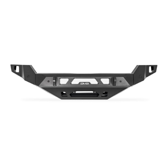
MTO WINCH FRONT BUMPER
2022+ (3RD GEN) TOYOTA TUNDRA
FBTT2-04
TOOLS
REQUIRED
- 10mm, 12mm, 13mm, 14mm, 16mm,
17mm Socket
- 10mm, 13mm, 14mm, 18mm, 18mm
Wrench
- 4mm, 5mm Allen Bit
- Trim Clip Tool
- Flat Head, Philips Head Screwdriver
- Angle Grinder
- Scissors or Shears
- Boxcutter Blade or Knife
- File or Sandpapaer
- HD Double Sided Tape, Painters Tape
- Measuring Tape
- Sharpie
WARNINGS/CAUTIONS BEFORE STARTING INSTALLATION
Before you install this kit —
instructions, warnings, cautions, and notes contained in
this installation instruction guide. Consult your vehicle
owner's manual for proper disconnection of electrical and
lifting of vehicle if required for installation of this product.
This install may require some technical skills and
knowledge of basic mechanical work. If you do not feel that
you are capable of performing this install please take this
product to a trained professional.
After reading this guide please contact us with any
questions or concerns before installing product.
Customer Service: 855-680-9595
DV8 Offroad is not responsible for any bodily injury or harm to you
or your vehicle as a result of an improper install.
6400 SYCAMORE CANYON BLVD.
RIVERSIDE, CALIFORNIA 92507
855-680-9595
WWW.DV8OFFROAD.COM
SKILL
LEVEL
- Intermediate/Difficult
- 2 persons
Intermediate skill level required.
Assistance is necessary for
installation.
Read and understand all
PRODUCT
INSTALLATION
TIME
- 4-6 Hours
Time to install this should take
between 4-6 hours based on
experience.
Proper installation of this kit required knowledge of the factory
recommended procedures for removal and installation of original
equipment components. We recommend that the factory shop manual
and any special tools needed to service your vehicle be on hand during
the installation. Installation of this kit without proper knowledge of the
factory recommended procedures may affect the performance of these
components and the safety of the vehicle
• Always wear eye protection when operating power tools
Inspect all contents of this package to make sure product is not damaged
and all installation hardware has been included. If parts are missing from
kit, please be prepared to provide the following information
1. Name of purchase location
2. Bar Code on side of box
3. Date above bar code
4. Date inside box cover
NEED HELP?
MANUAL
REQUIRED
855-680-9595
Advertisement

Related Manuals for DVB FBTT2-04


Summary of Contents for DVB FBTT2-04
- Page 1 PRODUCT INSTALLATION MANUAL RIVERSIDE, CALIFORNIA 92507 855-680-9595 WWW.DV8OFFROAD.COM MTO WINCH FRONT BUMPER 2022+ (3RD GEN) TOYOTA TUNDRA FBTT2-04 TOOLS REQUIRED - 10mm, 12mm, 13mm, 14mm, 16mm, 17mm Socket - 10mm, 13mm, 14mm, 18mm, 18mm Wrench - 4mm, 5mm Allen Bit...
- Page 2 INSTALLATION MANUAL FACTORY BUMPER UNINSTALL STEP 1 | Use a trim clip tool and 10mm socket to remove the fasteners securing the inner fender to the vehicle. NEED HELP? 855-680-9595...
- Page 3 INSTALLATION MANUAL STEP 2 | Pull back the inner fender to access the front bumper once the inner fender fasteners are all removed. STEP 3 | Using firm pressure, pull the fender flare away from the truck to the side to release the clips. Once released, pull the side of the bumper down slightly and to the side to release the clips between the bumper and fender.
- Page 4 INSTALLATION MANUAL STEP 5 | Use a trim clip tool to remove the push clips next to the wiring plugs located next to the headlights at both ends of the vehicle. Then disconnect the plugs. Note: Number of wire connectors may vary based on options/trim level of the vehicle.
- Page 5 INSTALLATION MANUAL STEP 7 | Use a trim clip tool to remove the fasteners securing the wiring plugs located behind the bumper in the fender well area on both sides of the vehicle. Then disconnect the plugs. STEP 8 | Disconnect the wiring plugs located behind the grille on the passenger side of the vehicle underneath the grille’s...
- Page 6 INSTALLATION MANUAL STEP 9 | Use a 10mm socket to remove the bolts securing the grille to the vehicle. These are located: -Along the radiator frame brace under the hood. -Underneath the vehicle along the bottom of the bumper. -Behind the trim pieces on both sides of the vehicle underneath the headlights.
- Page 7 INSTALLATION MANUAL STEP 11 | Use a 17mm socket or wrench to remove the bolts securing the crash bar. Then set the crash bar and braces off to the side. STEP 12 | Use a 10mm socket to remove bolts securing the vertical cross braces from the vehicle.
- Page 8 INSTALLATION MANUAL STEP 13 | Use a 10mm socket to remove the bolt securing the cooling hose bracket and set off to the side. STEP 14 | Use a 12mm socket to remove the bolts securing the skid plate if you have one, and set it off to the side.
- Page 9 INSTALLATION MANUAL Begin by unpacking all items and inspecting for missing pieces or damage. If you have any concens, please contact the company the product was purhcased from. Extra hardware may be included with the product. HARDWARE INCLUDED (6) M14x35 Hex (7) M8 Flat Washers (12) M14 Flat Washers (1) M8 Wide Flat Washer...
- Page 10 INSTALLATION MANUAL STEP 19 | If you are installing a fairlead, do so at this time using the hardware provided with the fairlead. STEP 17 | Install the winch plate using the provided M14 hardware and a 21mm and 19mm wrench. If you are running a winch, install it at this time using the hardware provided with the winch.
- Page 11 INSTALLATION MANUAL STEP 20 | If you are running a light bar, install lightbar on to the provided brackets using the hardware provided with the light. Install the light bar brackets on the bumper, then align and secure using the provided M6x20 hardware with a 4mm allen bit and 10mm wrench.
- Page 12 INSTALLATION MANUAL STEP 22 | On the factory bumper. remove the sensors by gently spreading the outside tabs. Remove the sensor plugs using a trim clip tool. You can use light heat to help this process. Tip: These plugs and sensors must be installed on the new bumper in the same location that they were removed.
- Page 13 INSTALLATION MANUAL STEP 24 | Remove the sensor wiring harness from the factory bumper by unclipping the fasteners securing it using a trim clip tool. STEP 25 | Install the sensor plugs into the bumper correlating to the factory locations. Tip: Reference the marked painters tape.
- Page 14 INSTALLATION MANUAL STEP 27 | Use a 10mm socket to remove the bolts located at the top and bottom of the shutters and set off to the side. Disconnect the adaptive cruise control and then use a philips head screwdriver to remove it from the grille if equipped.
- Page 15 INSTALLATION MANUAL STEP 29 | Use an angle grinder to grind the bottom mounting tabs off so they are flush with the rest of the grille. Note: The remainder of this install involves lots of cutting. Always be patient and take precise measurements when prompted.
- Page 16 INSTALLATION MANUAL STEP 31 | Trim the bottom section of the upper mounting bracket. Everything below the bended section will be cutoff, leaving the mounting holes. Clean up any rough edges. STEP 32 | Install the upper mount that mounts to the vehcile back onto the grille by clipping it back into place on the grille.
- Page 17 INSTALLATION MANUAL STEP 33 | Secure the adaptive cruise control using the factory screw and philips head screwdriver. Place the spacers onto the ACC and then place the provided spacer bracket on top. Use a 4mm allen bit and provided M6x25 hardware to secure.
- Page 18 INSTALLATION MANUAL STEP 36 | Install the “L” shaped brackets on the bottom of the grille. These should be installed so that the flat section will touch the bumper when installed. (Long slot will mount to these holes) Use the provided M8 hardware with a 5mm allen bit and 13mm wrench.
- Page 19 INSTALLATION MANUAL STEP 37 | On the air dam motor use a trim clip tool to remove the cap. Then use a 14mm socket and wrench to remove the bolts and nut securing the arm. STEP 38 | Remove the black caps, the white plastic spacers and the spring from the inside, and set the arm off to the side.
- Page 20 INSTALLATION MANUAL STEP 39 | Cut the flat section off of the arm as shown. STEP 40 | Place the arm back into the motor and install the spring, white plastic spacers, and black caps. Then secure using the factory hardware with a 14mm wrench and socket.
- Page 21 INSTALLATION MANUAL STEP 41 | Trim the plastic section with the two factory mounting holes off of the motor as shown. HOLES WITH THE ARROWS WILL BE REUSED, DO NOT CUT THESE STEP 42 | Trim the small remaining mounting tab off the motor as shown. NEED HELP? 855-680-9595...
- Page 22 INSTALLATION MANUAL STEP 43 | Replace cap on the air dam motor. STEP 44 | Use a 10mm socket to remove the bolt securing the cooling hoses to bracket located in front of the radiator on the passenger side. NEED HELP? 855-680-9595...
- Page 23 INSTALLATION MANUAL STEP 45 | Remove the cooling hoses running in front of the radiator from their plastic retaining clips. STEP 46 | Use a 10mm socket to remove the bolt securing the vertical cross brace. Slip the cooling hose behind the cross brace and re-secure using the factory hardware.
- Page 24 INSTALLATION MANUAL STEP 47 | On the passeneger side, push back on the hose mounting bracket to give the hoses some slack and then re-secure the hoses using the factory hardware and a 10mm socket. Replace the upper cooling hose in its plastic retaining clips Tip: Zip tie the lower cooling hose to the center brace at this time ensuring it clears the winch...
- Page 25 INSTALLATION MANUAL STEP 50 | Secure air dam motor wiring harness to vertical center cross brace using the factory clip. Note: Air dam motor should have a healthy gap between it and the radiator. The radiator hose running behind the air dam motor should not be too taught or too loose, and should also have a gap between it and the radiator.
- Page 26 INSTALLATION MANUAL STEP 53 | Secure the top section of the grille to the radiator frame using the factory hardware and mounting holes with a 10mm socket. STEP 54 | Use the provided M6 hardware and a 4mm allen bit to secure the lower section of the grille to the bumper.
- Page 27 INSTALLATION MANUAL STEP 56 | Re-secure wiring harness to the grille using factory clips by applying pressure until it “clips” into place. STEP 57 | Connect the wiring located behind the bumper in the fender well on both passenger and driver side of vehicle. (From Step 7) Connect the wiring to the plug located on the shutters.
- Page 28 INSTALLATION MANUAL STEP 59 | Install the outer trim of the grille by applying pressure to press the clips into place. STEP 60 | Vehicle must be resting on the ground and not on a lift or jack stands when cutting. Adjust the wings on the bumper to and when you are satisfied with fitment, secure them using an 18mm and 19mm...
-
Page 29: Installation
INSTALLATION MANUAL STEP 61 | Secure the side trim pieces from behind the bumper using the factory clips and screws with a philips headscrewdriver. Utilize the screw from the tab under the headlight to secure side trim pieces by screwing it into the tabs mounting hole. NEED HELP? 855-680-9595... - Page 30 INSTALLATION MANUAL STEP 62 | Mark the fender flare trim with painters tape, using the bumper and fender as a guide. Clean up any rough edges and secure it by applying pressure until it “clips” into place. STEP 63 | Remove the factory bolt in front of the wheel and behind the bumper using a 17mm socket.
- Page 31 INSTALLATION MANUAL STEP 64 | Use scissors or a blade to trim the inner fenders using the mounting points as a guide. Once finished, re-install the factory clips and bolts using a 10mm socket to secure the inner fender to the vehicle. STEP 65 | Re-install the skidplate using the factory hardware and a 12mm...
Need help?
Do you have a question about the FBTT2-04 and is the answer not in the manual?
Questions and answers