Table of Contents
Advertisement
Quick Links
Advertisement
Table of Contents

Related Manuals for MIYAWAKI RE2 Series


Summary of Contents for MIYAWAKI RE2 Series
- Page 1 DIRECT-ACTING PRESSURE REDUCING VALVE USER'S MANUAL...
-
Page 2: Table Of Contents
SAFETY GUIDE In order to get maximum benefit from this product, be sure to read this manual before installing it. The following warnings and cautions are shown at appropriate places in this manual. Failure to observe this type of precaution may lead to serious injury or death. -
Page 3: Purpose Of Use
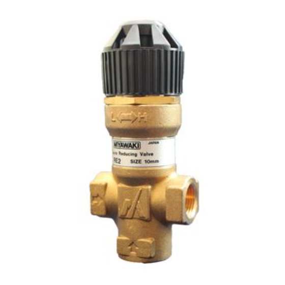
1. Purpose of use The type RE2 is a compact and lightweight direct-acting pressure reducing valve for steam that employs MIYAWAKI’s proprietary micro-bellows. It is most suitable for small steam equipment and steam irons in, for example, the sawing and laundering industries. -
Page 4: Construction Detials
3. Construction details Body 9. Sleeve Gasket Cover 10. Handle Gasket Plug 11. Seat bushing Lock nut Valve 12. Shaft Spring Valve seat 13. Spring Screw Bellows 14. Adjust bolt Washer Spring stay 15. Screen Name plate Spring 16. Gasket - 2 -... -
Page 5: Precautions For Piping
4. Precautions for piping Before installing the product, open both isolation valves and the bypass valve, Caution ! 注意 if one exists, to blow out any debris or dirt inside the pipeline. 1) Take care to prevent the condensate from entering the pressure reducing valve. If condensate flows into the pressure reducing valve, it can cause hunting and other phenomena and may damage the sealing surface of the valve and valve seat, as well as the sliding section. -
Page 6: Pressure Adjustment Procedure
5. Pressure adjustment procedure 19. Lock nut 1) Blow off low temperature condensate and foreign substances in the piping before flowing steam in the pressure reducing valve. 2) Make sure that the stop valves upstream and downstream of the pressure reducing valve are completely closed. -
Page 7: Troubleshooting
6. Troubleshooting The primary pressure does not 6-1) increase. The secondary pressure does not Pressure gauge Pressure gauge 6-2) increase to the set pressure. The secondary 6-3) pressure exceeds Stop valve Stop valve the set pressure. The handle cannot 6-4) be operated. - Page 8 6-3) Phenomenon: The secondary side pressure increases beyond the set pressure. 6-3) Phenomenon: The secondary side pressure increases beyond the set pressure. Cause of the problem Action Incorrect pressure setting. Turn the handle (10) for re-adjustment. The consumption on the secondary side Install a trap on the secondary side of the is close to zero.
-
Page 9: Maintenance
7. Maintenance Before you take off or disassemble the pressure reducing valve from the piping, be sure to close the stop valves on the inlet and outlet sides of the pressure reducing valve. When the assembly/disassembly is being performed, check that the pressure Warning !... - Page 10 7-4. How to disassemble the adjusting section 1) Pull the handle (10) gently and turn it to the right (direction of arrow L) to free the adjusting spring (8). (When the spring 21. Screw (8) is free, the handle turns very lightly.) 22.
-
Page 11: Warranty
8. Warranty 8. Warranty 8-1 Warranty period 8-1 Warranty period The warranty period shall last 12 months from the date of product delivery. The warranty period is 18 months after shipment or 12 months after installation, whichever occurs first. The warranty period shall last 12 months from the date of product delivery. 8-2 Details of the warranty 8-2 Details of the warranty If the product stops working correctly within the warranty period, we will repair or replace the... -
Page 12: Serial Number (S.no.) Designation
9 Serial number (S.No.) designation S.No. Represents the day. Represents the month. Represents the year. (last two digits of the year according to the Western calendar) Month designation system Symbol Month Symbol Month Symbol Month Symbol Month Day designation system Symbol Day Symbol Day Symbol Day Symbol Day Example of serial number designation... -
Page 13: Guidance For Reading Special Product Name
Guidance for reading special product name 〇〇〇-○○-□ Special symbol: Symbol apply only to special product (Please refer to table 1 for details) English letter after “-“ Model symbol: Product model number Table 1 Symbol description Suffix Special contents Trap for high-pressure gas installed property (only for Gas Trap) Blow valve attached Change of gasket Special face to face dimension... - Page 14 MIYAWAKI INC. Some special specifications of the product you have, may found to be different from the ones in the user's manual. If you have any question, please contact MIYAWAKI, our local authorized agent, or the place where you purchased.
- Page 15 INTERNATIONAL SALES DEPT. 2-1-30, Tagawakita, Yodogawa-ku, Osaka, 532-0021, Japan Tel: +81-6-6302-5549 www.miyawaki.net e-mail: export@miyawaki-inc.co.jp EU Importer and Authorized representative: MIYAWAKI GmbH Birnbaumsmühle 65, 15234 Frankfurt (Oder), Germany Tel: +49-335-4007-0097 www.miyawaki.net e-mail: info@miyawaki.de China Importer and Authorized representative: MIYAWAKI WEST Co.,ltd Room 1705, No.1, Building,No.311, Yanxin Road, Huishan Economic Development Zone,...
Need help?
Do you have a question about the RE2 Series and is the answer not in the manual?
Questions and answers