Table of Contents
Advertisement
Quick Links
Advertisement
Table of Contents

Related Manuals for MIYAWAKI AE8


Summary of Contents for MIYAWAKI AE8
- Page 1 INVERTED BUCKET AIR TRAP USER'S MANUAL...
-
Page 2: Table Of Contents
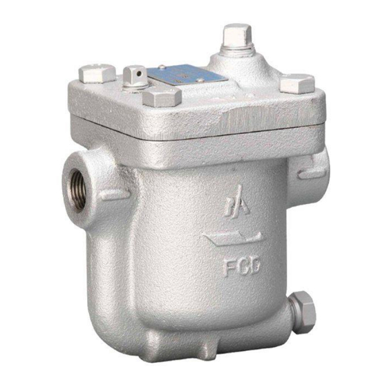
SAFETY GUIDE The model AE8 is a ductile cast iron inverted bucket air trap for discharging condensate from air piping, receiver tanks and compressed air systems. In order to get maximum benefit from this product, be sure to read this manual before installing it. -
Page 3: Specifications And Markings
Model: Showing the product model name Some pictures and illustrations in this manual are examples of AE8 models. For more details regarding dimensions and other specifications, please refer to the catalog. The model AE8 fully complies with the requirements of the European Pressure Equipment Directive 2014/68/EU. -
Page 4: Construction Details
CONSTRUCTION DETAILS Body Bucket 18. Name Plate Cover 10. Eyebolt 19. Rivet Plug 12. Eyebolt Pin 20. Cover Bolt Plug 13. Lever 21. Cover Gasket Valve Seat 14. Bracket 22. Injection Plug Valve 15. Pin 23. Vent Cleaner Valve Holder 16. -
Page 5: Installation
INSTALLATION WARNING Pay very careful attention when working in hazardous environments. There is a risk of explosion and the possibility of dangerous gases leaking. Always check whether the pipeline contains flammable, high pressure or high temperature materials before starting to work. ... - Page 6 2) Check the flow direction indicated on the body. 3) When installing the model AE8, install it so that the flow from the upstream line to the downstream line is horizontal and the name plate is on the top side of the body. When installing the trap in a horizontal line, be sure to maintain a slight slope of the line, so that any condensate will flow smoothly to the trap.
-
Page 7: Operation
OPERATION CAUTION Before starting operation, open the bypass valve or blow valve completely and blow off the scale in the piping. 4.1 Operation procedure 1) After blowing off the scale from the piping, close the bypass valve or blow valve. 2) Open the stop valve on the trap outlet side. -
Page 8: Maintenance
CAUTION When replacing parts, make sure the replacement parts are supplied by MIYAWAKI. The performance of air traps deteriorates gradually over time due to wear, corrosion or dirt accumulating around the valve and the valve seat. Please conduct periodic diagnosis of traps in order to keep air control systems and equipment working well. - Page 9 6.Valve 9.Bucket Internal Unit 5.Valve Seat 16.Set Bolt 16.Set Bolt 2.Cover 15.Pin Fig. 5 Fig. 4 Take appropriate measures according to “6. Troubleshooting”. After cleaning the trap and replacing damaged parts, re-assemble the parts in reverse order as follows. Refer to the torque table for each part.
- Page 10 (22) Body (20) Cover (19) Plug Plug (18) Valve Seat (21) Valve Valve Holder (24) (14) (15) (16) Bucket Eyebolt (12) Eyebolt Pin (13) Lever (23) Bracket (10) Set Bolt Screen Name Plate Rivet Cover Bolt (17) Cover Gasket Injection Plug Vent Cleaner Seat Gasket...
-
Page 11: Troubleshooting
TROUBLESHOOTING Problem Possible cause Solution Air leaks or blows through. amount in Remove the injection plug (22) condensate the body (1) is extremely small, and pour water into the body and the valve opening state (1). continues due to the sinking of the bucket (9). -
Page 12: Warranty
Problems caused by devices or equipment other than MIYAWAKI’s, or a disallowed use environment When a repair or modification has been performed by anyone other than MIYAWAKI or people who are authorized to make such repairs Intrusion of salt or other substances that promote significant rust or corrosion or problems from fluids that contain the same substances Consumable parts such as Packing, Gasket, O-ring, Diaphragm, etc. -
Page 13: Serial Number (S. No.) Designation
1 7 1 1 → Jan.1, 2017 2 9 X M → Oct. 21, 2029 ●For 9-digit display S.No. □□□□□□□□□ MIYAWAKI identification number Represents the month. Represents the year. (last two digits of the year according to the Western calendar) Example of serial number designation 1 7 1 1 2 C 0 2 0 →... -
Page 14: Guidance For Reading Special Product Name
GUIDANCE FOR READING SPECIAL PRODUCT NAME 〇〇〇-○○-□ Special symbol: The symbol applies only to special products (Please refer to table 1 for details) Model symbol: Product model number Table 1 Symbol description Suffix Special contents Trap for high-pressure gas installed property (only for Gas Trap) Blow valve attached Change of gasket Special face to face dimension... - Page 15 MIYAWAKI INC. Some special specifications of the product you have, may found to be different from the ones in the user's manual. If you have any question, please contact MIYAWAKI, our local authorized agent, or the place where you purchased.
- Page 16 INTERNATIONAL SALES DEPT. 2-1-30, Tagawakita, Yodogawa-ku, Osaka, 532-0021, Japan Tel: +81-6-6302-5549 www.miyawaki.net e-mail: export@miyawaki-inc.co.jp EU Importer and Authorized representative: MIYAWAKI GmbH Birnbaumsmühle 65, 15234 Frankfurt (Oder), Germany Tel: +49-335-4007-0097 www.miyawaki.net e-mail: info@miyawaki.de China Importer and Authorized representative: MIYAWAKI WEST Co.,ltd Room 1705, No.1, Building,No.311, Yanxin Road, Huishan Economic Development Zone,...
Need help?
Do you have a question about the AE8 and is the answer not in the manual?
Questions and answers