Table of Contents
Advertisement
Quick Links
Advertisement
Table of Contents

Related Manuals for MIYAWAKI SV1


Summary of Contents for MIYAWAKI SV1
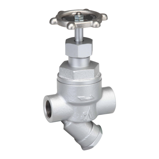
- Page 1 THERMODYNAMIC STEAM TRAP USER'S MANUAL...
-
Page 2: Table Of Contents
SAFETY GUIDE The model SV1 is a compact, disc type steam trap that also serves as a bypass valve. In order to get maximum benefit from this product, be sure to read this manual before installing it. The following warnings and cautions are shown at appropriate places in this manual. -
Page 3: Specifications And Markings
SPECIFICATIONS AND MARKINGS WARNING Be sure not to use this product at higher pressures than the specified maximum allowable pressure (PMA) or at temperatures higher than the specified maximum allowable temperature (TMA). The following items are displayed on the name label or the side of the product. Check each item to avoid misuse of the product. -
Page 4: Construction Details
CONSTRUCTION DETAILS (17) (19) (20) (15) (10) (18) (14) (16) (13) (11) (12) Body Spindle 15. Gland bush B Bonnet Gland Packing 16. Pin Seat 10. Gland Nut 17. Handle Disc 11. Screen 18. Gland Bush A 12. Plug 19. Nut Bush 13. -
Page 5: Installation
2) Check the flow direction indicated on the side of the body. 3) The SV1 can be used for both horizontal and vertical lines. However, when installing a SV1 in a horizontal line, be sure to maintain a slight slope to the line, so that any condensate will flow smoothly. -
Page 6: Operation
・In normal operation, use the SV1 with the bypass valve closed (with the handle turned fully clockwise). ・If the SV1 is used for a long time with the bypass valve open, there is a possibility that parts such as the Valve Seat may be damaged. -
Page 7: Maintenance
Therefore, be very careful. CAUTION When replacing parts, make sure the replacement parts are supplied by Miyawaki. The performance of steam traps deteriorates gradually over time due to wear, corrosion, or dirt accumulating around the valve seat. - Page 8 5.3.1 Disassembling the trap 1) Remove the bonnet (2). 2) The trap unit, including the handle (17), can be taken out as one unit. 3) When the handle (17) turns clockwise, it will come into contact with the gland nut (10). 4) When the spindle (8) connected to the handle (17) is tilted against the trap unit, as shown in the figure on the right, it can be taken out.
- Page 9 5.3.6 Reassembling the trap 1) Put the disc (4) on the surface of the seat (3) in the body (1). *The disc with a groove should be facing down. 2) Fasten the cap (5) on the seat (3). 3) With the handle (17) touching the gland nut (10), connect the spindle (8) to the trap unit, as shown in the figure on the right.
- Page 10 (19) Body Bonnet (20) Seat Disc (17) Bush Valve Seat (10) Spindle Gland Packing (15) 10. Gland Nut 11. Screen 12. Plug (18) 13. Plug Gasket 14. Bonnet Gasket 15. Gland Bush B 16. Pin 17. Handle (14) 18. Gland Bush A 19.
-
Page 11: Troubleshooting
TROUBLESHOOTING Problem Possible cause Solution Steam leaks or blows Dirt is stuck around the disc (4) Clean the disc (4) and the seat or seat (3). (3). through. Damage, wear or corrosion of Replace the trap unit. the disc (4) Damage, wear or corrosion of Replace the trap unit. -
Page 12: Warranty
WARRANTY 7.1 Warranty period The warranty period is 18 months after shipment or 12 months after installation, whichever occurs first. 7.2 Details of the warranty If the product stops working correctly within the warranty period, we will repair or replace the product free of charge if the cause of the trouble is not one of the following items. -
Page 13: 8 Serial Number(S. No.)Designation
1 7 1 1 → Jan.1, 2017 2 9 X M → Oct. 21, 2029 ●For 9-digit display S.No. □□□□□□□□□ MIYAWAKI identification number Represents the month. Represents the year. (last two digits of the year according to the Western calendar) Example of serial number designation 1 7 1 1 2 C 0 2 0 →... -
Page 14: Guidance For Reading Special Product Name
GUIDANCE FOR READING SPECIAL PRODUCT NAME 〇〇〇-○○-□ Special symbol: Symbol apply only to special product (Please refer to table 1 for details) English letter after “-“ Model symbol: Product model number Table 1 Symbol description Suffix Special contents Trap for high-pressure gas installed property (only for Gas Trap) Blow valve attached Change of gasket Special face to face dimension... - Page 15 MIYAWAKI INC. Some special specifications of the product you have, may found to be different from the ones in the user's manual. If you have any question, please contact MIYAWAKI, our local authorized agent, or the place where you purchased.
- Page 16 MIYAWAKI GmbH Birnbaumsmühle 65, 15234 Frankfurt (Oder), Germany Tel: +49-335-4007-0097 www.miyawaki.de e-mail: info@miyawaki.de China Importer and Authorized representative: MIYAWAKI WEST Co., Ltd Room 1705, No.1, Building,No.311, Yanxin Road, Huishan Economic Development Zone, Wuxi, Jiangsu, China Tel: +86-510-8359-5125 www.miyawaki-inc.com.cn e-mail: mywkwest@miyawaki-inc.com.cn...
Need help?
Do you have a question about the SV1 and is the answer not in the manual?
Questions and answers