Table of Contents
Advertisement
Quick Links
Advertisement
Table of Contents

Related Manuals for MIYAWAKI RE1


Summary of Contents for MIYAWAKI RE1
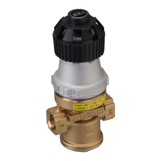
- Page 1 DIRECT ACTING PRESSURE REDUCING VALVE USER'S MANUAL...
-
Page 2: Table Of Contents
SAFETY GUIDE The model RE1 is a direct acting pressure reducing valve designed for use in stream lines. In order to get maximum benefit from this product, be sure to read this manual before installing it. The following warnings and cautions are shown at appropriate places in this manual. -
Page 3: Specifications And Markings
Primary pressure range (PRIMARY P.): Range of the pressure in the primary side at which the pressure reducing valve will operate properly. RE1: 0.2-1.6MPa (29-230psig) RE1-4, RE1-2: 0.2-1.0MPa (29-145psig) Secondary pressure range (SECONDARY P.): The range of reduced pressure on the secondary side that can be set. -
Page 4: Construction Details
CONSTRUCTION DETAILS RE1-2 RE1-4 1. Body Handle Unit 3. Plug 2. Cover 4. Valve 8. Main Spring 5. Valve Seat 9. Sleeve 6. Bellows 10. Handle 11. Orifice Plate 14. Adjust Bolt 12. Shaft 19. Taper Pin 13. Stop Ring 22. -
Page 5: Installation
INSTALLATION WARNING Do not touch the pressure reducing valve, safety valve (relief valve) or the opening section on the pipe outlet side with your bare hand. If there is steam present, you may be seriously injured. Before supply of steam, check whether there will be any danger if the steam reaches the end of the pipe and whether all the pipe joints have been connected. - Page 6 6) Install a steam trap on the secondary side of the pressure reducing valve so that the condensate can be discharged when equipment or systems stop being used. 7) The pressure reducing valve should be installed in a horizontal pipe with the operating part including the adjust unit turned upward.
- Page 7 10) Avoid using the pressure reducing valves in parallel. The pressure reducing valve is self-actuated type, and each has its own variation in sensitivity and responsiveness to pressure. Therefore, since two pressure reducing valves cannot be activated exactly in the same way, only one valve would actually be doing the work. That’s why they need to be used independently.
- Page 8 13) When using a control valve on the secondary side of the pressure reducing valve, install the control valve so that the distance between the pressure reducing valve and the control valve is 2 m (6.6 ft) or more.(Otherwise, the pressure reducing valve operation may be unstable.) 2 m (6.6 ft) Control valve...
- Page 9 16) Secure or support the pipe so that any load, bending or vibration in the pipe is not transmitted directly to the pressure reducing valve. 17) Most complaints about direct acting pressure reducing valves installed in new pipes or in pipes that have not been used for a long time are due to dirt and scale in the pipes.
- Page 10 Plumbing example 1m (3.3 ft) or more Distance of 10 Y-type times the pipe strainer Secondary diameter side Distance of 10 times the pipe Pressure diameter gauge Stop valve Direct acting pressure reducing Separator valve Stop valve Primary side Sight glass Steam trap DC 1 type Stop valve Clearance for Proper Maintenance...
-
Page 11: Pressure Adjustment Method
PRESSURE ADJUSTMENT METHOD WARNING Since the handle gets hot when the pressure is adjusted, wear work gloves or leather gloves. Otherwise, you may be burned. Do not touch the pressure reducing valve, the safety valve (relief valve) or the opening section on the pipe outlet side with your bare hand. -
Page 12: Maintenance
MAINTENANCE WARNING Before removing the pressure reducing valve from the pipe or disassembling it, be sure to close the stop valves at the inlet and outlet of the pressure reducing valve. Then, release the remaining pressure in the pressure reducing valve body (check whether the pressure in the body has reached 0 MPa (0 bar)), and let it cool down completely (check whether the surface temperature of the body is at room temperature). - Page 13 (3). Secure the plug (3) in the body (1). RE1-2 Put the curved side of the valve faces the return spring (16) on the small diameter end portion of the return spring, and reinstall them in the plug (3).
- Page 14 2.2) Replacing the bellows and shaft sections ○ Disassembly Lift the handle (10) gently, turn it clockwise (in the direction indicated by arrow L) to free the main spring (8) and then loosen the cover. Remove the cover (2) (handle unit), and take out the main spring (8). ...
- Page 15 Handle Unit 8. Main Spring 22. Cover Gasket 6. Bellows 23. Bellows Gasket 13. Stop Ring 12. Shaft 11. Orifice Plate 1. Body 21. Seat Gasket 5. Valve Seat 4. Valve 16. Return Spring 17. Screen 20. Plug Gasket 3. Plug...
-
Page 16: Troubleshooting
TROUBLESHOOTING Corrective Symptom action Pressure Pressure reducing valve The primary side pressure ⇒ gauge Pressure does not increase. gauge The secondary side pressure Stop valve Stop valve ⇒ (2) does not increase to the set pressure. The secondary side pressure ⇒... - Page 17 Working Reference Cause of the problem Corrective action conditions item Clogged screen (17) Clean the screen (17).If it is Due to Item 5-2)- damaged, replace it with a new internal 2.1) one. parts Poor sliding of the shaft (12) Clean the sliding section between the shaft (12) and the orifice plate Item 5-2)- (11).
- Page 18 (5) Symptom: Chattering occurs. (Vibration noise from the valve) Working Reference Cause of the problem Corrective action conditions item Due to Condensate flows in from the Install a trap on the primary side of primary side the pressure reducing valve. plumbing Used below the minimum Select a new pressure reducing...
-
Page 19: Warranty
WARRANTY 7.1 Warranty period The warranty period is 18 months after shipment or 12 months after installation, whichever occurs first. 7.2 Details of the warranty If the product stops working correctly within the warranty period, we will repair or replace the product free of charge if the cause of the trouble is not one of the following items. -
Page 20: Serial Number (S. No.) Designation
8 SERIAL NUMBER (S. No.) DESIGNATION S.No. □□□□ Represents the day. Represents the month. Represents the year. (last two digits of the year according to the Western calendar) Month designation system Month Symbol Month Symbol Month Symbol Month Symbol Day designation system Symbol Symbol Symbol... -
Page 21: Guidance For Reading Special Product Name
GUIDANCE FOR READING SPECIAL PRODUCT NAME 〇〇〇-○○-□ Special symbol: Symbol apply only to special product (Please refer to table 1 for details) English letter after “-“ Model symbol: Product model number Table 1 Symbol description Suffix Special contents Trap for high-pressure gas installed property (only for Gas Trap) Blow valve attached Change of gasket Special face to face dimension... - Page 22 MIYAWAKI INC. Some special specifications of the product you have, may found to be different from the ones in the user's manual. If you have any question, please contact MIYAWAKI, our local authorized agent, or the place where you purchased.
- Page 23 INTERNATIONAL SALES DEPT. 2-1-30, Tagawakita, Yodogawa-ku, Osaka, 532-0021, Japan Tel: +81-6-6302-5549 www.miyawaki.net e-mail: export@miyawaki-inc.co.jp EU Importer and Authorized representative: MIYAWAKI GmbH Birnbaumsmühle 65, 15234 Frankfurt (Oder), Germany Tel: +49-335-4007-0097 www.miyawaki.net e-mail: info@miyawaki.de China Importer and Authorized representative: MIYAWAKI WEST Co.,ltd Room 1705, No.1, Building,No.311, Yanxin Road, Huishan Economic Development Zone,...
Need help?
Do you have a question about the RE1 and is the answer not in the manual?
Questions and answers