
Related Manuals for MIYAWAKI RE3


Summary of Contents for MIYAWAKI RE3
- Page 1 INSTALLATION,OPERATION and MAINTENANCE MANUAL Pilot Operated Pressure Reducing Valve...
- Page 2 SAFETY The following warnings and cautions are shown at appropriate places in this manual. Failure to observe this type of precaution may lead to serious injury or death. WARNING Failure to follow this type of precaution can lead to injury or damage to CAUTION equipment and property.
- Page 3 S No. on the name plate of our product indicates a manufacturing date. Indicating method of S No. S.No. indicates a day indicates a month indicates a year Example of indicating a year 2005 2015 Method of indicating a month Mark Month Mark...
-
Page 4: Table Of Contents
CONTENTS 1 INTRODUCTION 2 TECHNICAL DATA AND DIMENSION 3 INSTALLATION 4 INSTALLATION EXAMPLE 5 ADJUSTMENT 6 TROUBLE SHOOTING 7 MAINTENANCE 8 WARRANTY P.10 P.11 GUIDANCE FOR READING SPECIAL PRODUCT NAME... -
Page 5: Introduction
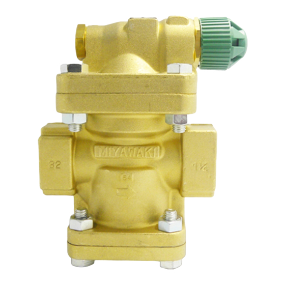
The MIYAWAKI – pressure reducing valve RE 3 is a pilot operated pressure regulator equipped with micro bellows and designed for use in steam lines. Prior to using the RE3 , read this manual thoroughly to understand the correct handling and operating procedure. -
Page 6: Installation
Installation 3.1. The pressure reducing valve should be installed in a horizontal pipe with the operating part including the adjust unit turned upwards, with suitable bypass and isolating valves. 3.2. To prevent water hammer and vibrations caused by incoming condensate it is necessary to install a steam trap before the pressure reducing valve. -
Page 7: Installation Example
3.13. The distance between the pressure reducing valve and a downstream pressure gauge should be of at least 1 meter. 3.14. The length of the straight section of the upstream piping and the length of the straight section of the downstream piping should be each at least 10 pipe diameters. 3.15. -
Page 8: Adjustment
Adjustment 5.1. After the installation and before the adjustment of the pressure reducing valve close the stop valves before and behind the pressure reducing valve and open the bypass to remove all condensate and dirt from the pipe. 5.2. Close the bypass valve and pull the green handle while the stop valves are closed. Turn the handle clockwise (looking from the outlet side towards the inlet side) to release the adjust spring. - Page 9 The screen (20) of the Remove the plug (3) and pressure reducing valve is clean the screen. plugged. The screen (21) before the Remove the plug (10) and pilot valve is plugged. clean the screen (21). Irregular movement of the Remove the plug (10) and pilot valve (11) due to dirt.
-
Page 10: Maintenance
7. Maintenance The disassembly, the assembly and the replacement of parts may, in general, be done with tools customary in the market. When you disassemble the valve, pay attention that you start the maintenance work only when the internal parts have cooled down and are not under pressure. 7.1. - Page 11 7.2. Valve and Valve Seat Nr. 3 - Plug Size ½ “ – 1“ Plug size 30 mm Torque 800 kgf • Nr. 38 – Bolt Size 1 ¼ “ – 2“ Bolt Size 17 mm Torque 250 kgf • Spare Parts Parts Name Gasket...
- Page 12 7.4. Valve Seat and Bellows Spare Parts Nr. 12 – Valve Seat Parts Name Gasket Measurement 14 mm Micro Bellows Torque 300 kgf • Valve Seat Unit Nr. 34 – Lock Nut Nr. 9 – Adjust Cover Measurement 35 mm Measurement 30 mm Torque...
- Page 13 Material Parts-No. Parts Name Material Body Brass Cover Brass Plug( ½ “-1“) Brass Bottom Flange Brass (1 ¼ “-2“) Valve Stainless Steel Disc Stainless Steel Spring Stainless Steel Piston Brass Cylinder Liner Brass Adjust Cover Brass Plug Brass Pilot Valve Stainless Steel Valve Seat Stainless Steel...
-
Page 14: Warranty
8. WARRANTY 8. WARRANTY 8.1 Warranty period 8.1 Warranty period The warranty period shall last 12 months from the date of product delivery. The warranty period is 18 months after shipment or 12 months after installation, The warranty period shall last 12 months from the date of product delivery. whichever occurs first. -
Page 15: Guidance For Reading Special Product Name
GUIDANCE FOR READING SPECIAL PRODUCT NAME Special symbol: symbol apply only to special product (Please refer to table 1 for details) English letter after “-“ Model symbol: Product model number Table 1 Symbol description Suffix Special contents Trap for high-pressure gas installed property Blow valve attached Change of gasket Special face to face dimension... - Page 16 MIYAWAKI INC. Some special specifications of the product you have, may found to be different from the ones in the user's manual. If you have any question, please contact MIYAWAKI, our local authorized agent, or the place where you purchased.
- Page 17 INTERNATIONAL SALES DEPT. 2-1-30, Tagawakita, Yodogawa-ku, Osaka, 532-0021, Japan Tel: +81-6-6302-5549 www.miyawaki.net e-mail: export@miyawaki-inc.co.jp EU Importer and Authorized representative: MIYAWAKI GmbH Birnbaumsmühle 65, 15234 Frankfurt (Oder), Germany Tel: +49-335-4007-0097 www.miyawaki.net e-mail: info@miyawaki.de China Importer and Authorized representative: MIYAWAKI WEST Co.,ltd Room 1705, No.1, Building,No.311, Yanxin Road, Huishan Economic Development Zone,...
Need help?
Do you have a question about the RE3 and is the answer not in the manual?
Questions and answers