Table of Contents
Advertisement
Quick Links
LOVATO ELECTRIC S.P.A.
24020 GORLE (BERGAMO) ITALIA
VIA DON E. MAZZA, 12
TEL. 035 4282111
L
E
E-mail info@
ovato
lectric.com
L
E
Web
www.
ovato
lectric.com
WARNING!
– Carefully read the manual before the installation or use.
– This equipment is to be installed by qualified personnel, complying to current standards, to avoid
damages or safety hazards.
– Before any maintenance operation on the device, remove all the voltages from measuring and supply inputs and short-
circuit the CT input terminals.
– The manufacturer cannot be held responsible for electrical safety in case of improper use of the equipment.
– Products illustrated herein are subject to alteration and changes without prior notice. Technical data and descriptions in
the documentation are accurate, to the best of our knowledge, but no liabilities for errors, omissions or contingencies
arising there from are accepted.
– A circuit breaker must be included in the electrical installation of the building. It must be installed close by the equipment
and within easy reach of the operator. It must be marked as the disconnecting device of the equipment:
IEC /EN 61010-1 § 6.11.3.1.
– Clean the device with a soft dry cloth; do not use abrasives, liquid detergents or solvents.
ATTENTION !
– Lire attentivement le manuel avant toute utilisation et installation.
– Ces appareils doivent être installés par un personnel qualifié, conformément aux normes en vigueur en
matière d'installations, afin d'éviter de causer des dommages à des personnes ou choses.
– Avant toute intervention sur l'instrument, mettre les entrées de mesure et d'alimentation hors tension et court-circuiter
les transformateurs de courant.
– Le constructeur n'assume aucune responsabilité quant à la sécurité électrique en cas d'utilisation impropre du dispositif.
– Les produits décrits dans ce document sont susceptibles d'évoluer ou de subir des modifications à n'importe quel
moment. Les descriptions et caractéristiques techniques du catalogue ne peuvent donc avoir aucune valeur contractuelle.
– Un interrupteur ou disjoncteur doit être inclus dans l'installation électrique du bâtiment. Celui-ci doit se trouver tout près
de l'appareil et l'opérateur doit pouvoir y accéder facilement. Il doit être marqué comme le dispositif d'interruption de
l'appareil : IEC/ EN 61010-1 § 6.11.3.1.
– Nettoyer l'appareil avec un chiffon doux, ne pas utiliser de produits abrasifs, détergents liquides ou solvants.
ACHTUNG!
– Dieses Handbuch vor Gebrauch und Installation aufmerksam lesen.
– Zur Vermeidung von Personen- und Sachschäden dürfen diese Geräte nur von qualifiziertem
Fachpersonal und unter Befolgung der einschlägigen Vorschriften installiert werden.
– Vor jedem Eingriff am Instrument die Spannungszufuhr zu den Messeingängen trennen und die Stromwandler
kurzschlie en.
– Bei zweckwidrigem Gebrauch der Vorrichtung übernimmt der Hersteller keine Haftung für die elektrische Sicherheit.
– Die in dieser Broschüre beschriebenen Produkte können jederzeit weiterentwickelt und geändert werden. Die im Katalog
enthaltenen Beschreibungen und Daten sind daher unverbindlich und ohne Gewähr.
– In die elektrische Anlage des Gebäudes ist ein Ausschalter oder Trennschalter einzubauen. Dieser muss sich in
unmittelbarer Nähe des Geräts befinden und vom Bediener leicht zugänglich sein. Er muss als Trennvorrichtung für das
Gerät gekennzeichnet sein: IEC/ EN 61010-1 § 6.11.3.1.
– Das Gerät mit einem weichen Tuch reinigen, keine Scheuermittel, Flüssigreiniger oder Lösungsmittel verwenden.
ADVERTENCIA
– Leer atentamente el manual antes de instalar y utilizar el regulador.
– Este dispositivo debe ser instalado por personal cualificado conforme a la normativa de instalación
vigente a fin de evitar daños personales o materiales.
– Antes de realizar cualquier operación en el dispositivo, desconectar la corriente de las entradas de alimentación y
medida, y cortocircuitar los transformadores de corriente.
– El fabricante no se responsabilizará de la seguridad eléctrica en caso de que el dispositivo no se utilice de forma
adecuada.
– Los productos descritos en este documento se pueden actualizar o modificar en cualquier momento. Por consiguiente,
las descripciones y los datos técnicos aquí contenidos no tienen valor contractual.
– La instalación eléctrica del edificio debe disponer de un interruptor o disyuntor. Éste debe encontrarse cerca del
dispositivo, en un lugar al que el usuario pueda acceder con facilidad. Además, debe llevar el mismo marcado que el
interruptor del dispositivo (IEC/ EN 61010-1 § 6.11.3.1).
– Limpiar el dispositivo con un trapo suave; no utilizar productos abrasivos, detergentes líquidos ni disolventes.
UPOZORN NÍ
– Návod se pozorn pro t te, než za nete regulátor instalovat a používat.
– Tato za ízení smí instalovat kvalifikovaní pracovníci v souladu s platnými p edpisy a normami pro p edcházení
úraz osob i poškození v cí.
– P ed jakýmkoli zásahem do p ístroje odpojte m icí a napájecí vstupy od nap tí a zkratujte transformátory proudu.
– Výrobce nenese odpov dnost za elektrickou bezpe nost v p ípad nevhodného používání regulátoru.
– Výrobky popsané v tomto dokumentu mohou kdykoli projít úpravami i dalším vývojem. Popisy a údaje uvedené v katalogu
nemají proto žádnou smluvní hodnotu.
– Spína i odpojova je nutno zabudovat do elektrického rozvodu v budov . Musejí být nainstalované v t sné blízkosti p ístroje a
snadno dostupné pracovníku obsluhy. Je nutno ho ozna it jako vypínací za ízení p ístroje: IEC/ EN 61010-1 § 6.11.3.1.
– P ístroj ist te m kkou ut rkou, nepoužívejte abrazivní produkty, tekutá istidla i rozpoušt dla.
AVERTIZARE!
– Citi i cu aten ie manualul înainte de instalare sau utilizare.
– Acest echipament va fi instalat de personal calificat, în conformitate cu standardele actuale, pentru a evita
deterior ri sau pericolele.
– Înainte de efectuarea oric rei opera iuni de între inere asupra dispozitivului, îndep rta i toate tensiunile de la intr rile de
m surare i de alimentare i scurtcircuita i bornele de intrare CT.
– Produc torul nu poate fi considerat responsabil pentru siguran a electric în caz de utilizare incorect a echipamentului.
– Produsele ilustrate în prezentul sunt supuse modific rilor i schimb rilor f r notificare anterioar . Datele tehnice i descrierile
din documenta ie sunt precise, în m sura cuno tin elor noastre, dar nu se accept nicio r spundere pentru erorile, omiterile sau
evenimentele neprev zute care apar ca urmare a acestora.
– Trebuie inclus un disjunctor în instala ia electric a cl dirii. Acesta trebuie instalat aproape de echipament i într-o zon u or
accesibil operatorului. Acesta trebuie marcat ca fiind dispozitivul de deconectare al echipamentului: IEC/EN 61010-1 § 6.11.3.1.
– Cur a i instrumentul cu un material textil moale i uscat; nu utiliza i substan e abrazive, detergen i lichizi sau solven i.
GB
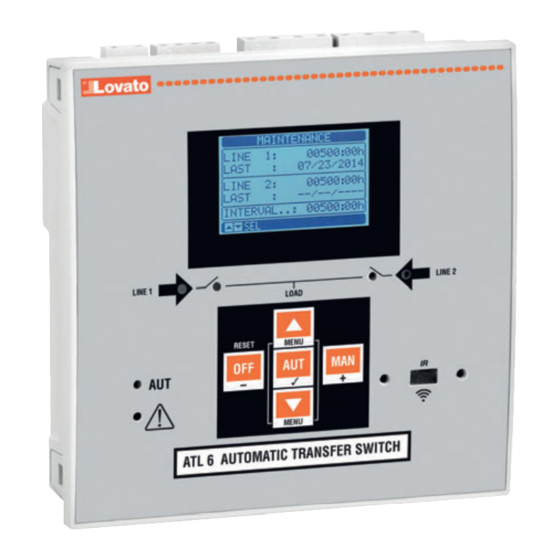
AUTOMATIC TRANSFER SWITCH CONTROLLER
Installation manual
PL
AUTOMATYCZNE STEROWNIKI UKŁADÓW SZR
Skrócona instrukcja obsługi
ATL 600 - ATL 601 - ATL 610
ATTENZIONE!
– Leggere attentamente il manuale prima dell'utilizzo e l'installazione.
– Questi apparecchi devono essere installati da personale qualificato, nel rispetto delle vigenti normative
impiantistiche, allo scopo di evitare danni a persone o cose.
– Prima di qualsiasi intervento sullo strumento, togliere tensione dagli ingressi di misura e di alimentazione e
cortocircuitare i trasformatori di corrente.
– Il costruttore non si assume responsabilità in merito alla sicurezza elettrica in caso di utilizzo improprio del dispositivo.
– I prodotti descritti in questo documento sono suscettibili in qualsiasi momento di evoluzioni o di modifiche. Le descrizioni
ed i dati a catalogo non possono pertanto avere alcun valore contrattuale.
– Un interruttore o disgiuntore va compreso nell'impianto elettrico dell'edificio. Esso deve trovarsi in stretta vicinanza
dell'apparecchio ed essere facilmente raggiungibile da parte dell'operatore. Deve essere marchiato come il dispositivo di
interruzione dell'apparecchio: IEC/ EN 61010-1 § 6.11.3.1.
– Pulire l'apparecchio con panno morbido, non usare prodotti abrasivi, detergenti liquidi o solventi.
UWAGA!
– Przed u yciem i instalacj urz dzenia nale y uwa nie przeczyta niniejsz instrukcj .
– W celu unikni cia obra e osób lub uszkodzenia mienia tego typu urz dzenia musz by instalowane przez
wykwalifikowany personel, zgodnie z obowi zuj cymi przepisami.
– Przed rozpocz ciem jakichkolwiek prac na urz dzeniu nale y od czy napi cie od wej pomiarowych i zasilania oraz zewrze
zaciski przek adnika pr dowego.
– Producent nie przyjmuje na siebie odpowiedzialno ci za bezpiecze stwo elektryczne w przypadku niew a ciwego u ytkowania
urz dzenia.
– Produkty opisane w niniejszym dokumencie mog by w ka dej chwili udoskonalone lub zmodyfikowane. Opisy oraz dane
katalogowe nie mog mie w zwi zku z tym adnej warto ci umownej.
– W instalacji elektrycznej budynku nale y uwzgl dni prze cznik lub wy cznik automatyczny. Powinien on znajdowa
si w bliskim s siedztwie urz dzenia i by atwo osi galny przez operatora. Musi by oznaczony jako urz dzenie s u ce
do wy czania urz dzenia: IEC/ EN 61010-1 § 6.11.3.1.
– Urz dzenie nale y czy ci mi kk szmatk , nie stosowa rodkow ciernych, p ynnych detergentów lub rozpuszczalników.
!
–
.
–
–
–
.
–
,
.
–
: IEC /EN 61010-1 § 6.11.3.1.
–
.
D KKAT!
– Montaj ve kullan mdan önce bu el kitab n dikkatlice okuyunuz.
– Bu aparatlar ki ilere veya nesnelere zarar verme ihtimaline kar yürürlükte olan sistem kurma normlar na göre
kalifiye personel taraf ndan monte edilmelidirler
– Aparata (cihaz) herhangi bir müdahalede bulunmadan önce ölçüm giri lerindeki gerilimi kesip ak m transformatörlerinede k sa
devre yapt r n z.
– Üretici aparat n hatal kullan m ndan kaynaklanan elektriksel güvenli e ait sorumluluk kabul etmez.
– Bu dokümanda tarif edilen ürünler her an evrimlere veya de i imlere aç kt r. Bu sebeple katalogdaki tarif ve de erler herhangi bir
ba lay c de eri haiz de ildir.
– Binan n elektrik sisteminde bir anahtar veya alter bulunmal d r. Bu anahtar veya alter operatörün kolayl kla ula abilece i yak n
bir yerde olmal d r. Aparat (cihaz) devreden ç kartma görevi yapan bu anahtar veya alterin markas : IEC/ EN 61010-1 § 6.11.3.1.
– Aparat (cihaz) s v deterjan veya solvent kullanarak yumu ak bir bez ile siliniz a nd r c temizlik ürünleri kullanmay n z.
The complete operating manual is downloadable from website www.lovatoelectric.pl
Kompletna instrukcja do pobrania ze strony www.lovatoelectric.pl
,
.
,
,
,
.
,
( ).
,
1
Advertisement
Table of Contents

Related Manuals for Lovato ATL 600


Summary of Contents for Lovato ATL 600
- Page 1 ATL 600 - ATL 601 - ATL 610 WARNING! ATTENZIONE! – Carefully read the manual before the installation or use. – Leggere attentamente il manuale prima dell’utilizzo e l’installazione. – This equipment is to be installed by qualified personnel, complying to current standards, to avoid –...
- Page 2 – 3 dostępne wykonania: • ATL 600 – base version, AC supply, non-expandable; • ATL 600 – wersja podstawowa, zasilanie pomocnicze AC, bez możliwości rozbudowy; • ATL 601 – base version, DC supply, non-expandable; • ATL 601 – wersja podstawowa, zasilanie pomocnicze DC, bez możliwości rozbudowy;...
-
Page 3: Menu Główne
(wyłączniki z napędem,przełączniki z napędem lub styczniki. POWER-UP NAPIĘCIE ZASILANIA – ATL 600 has 110-240VAC supply. – ATL 600 zasilany jest 110-240VAC. – ATL 601 has 12-24VDC supply. – ATL 601 zasilany jest 12-24VDC. – ATL 610 has 110-240VAC or 12-24VDC supply. In the case of the simultaneous presence of both power –... - Page 4 – The actual system configuration is shown in the dedicated page of the display (expansion modules), – Aktualna konfiguracja systemu wyświetlana jest na specjalnej stronie wyświetlacza (moduły where it is possible to see the number, the type and the status of the modules. rozbudowy), gdzie można zobaczyć...
- Page 5 PARAMETER SETTING (SETUP) WITH PC USTAWIENIA PRZY UŻYCIU KOMPUTERA – You can use the software configuration and the X-Press Remote control to transfer (previously – Za pomocą oprogramowania konfiguracyjnego Xpress istnieje możliwość przesłania parametrów programmed) setup parameters from the ATL 6... to the hard drive of the PC and vice versa. ustawień...
-
Page 6: Parameter Table
PARAMETER TABLE TABELA PARAMETRÓW M01 - UTILITY / UŻYTECZNE Domyślnie Zakres P01.01 Language / Język angielski angielski włoski francuski hiszpański niemiecki P01.02 Set real time clock at power-on / Ustawienie zegara po podłączeniu zasilenia OFF-ON P01.03 Power-on operating mode / Tryb działania po podłączeniu zasilenia Previous / OFF mode / tryb OFF Poprzedni... -
Page 7: Installation
ALARM TABLE TABELA ALARMÓW CODE DESCRIPTION OPIS Battery voltage too low Zbyt niskie napięcie akumulatora Battery voltage too high Zbyt wysokie napięcie akumulatora LINE 1 circuit breaker timeout Upłynął czas wyłącznika linii 1 LINE 2 circuit breaker timeout Upłynął czas wyłącznika linii 2 LINE 1 wrong phase sequence Niewłaściwa kolejność... -
Page 8: Wiring Diagrams
WIRING DIAGRAMS SCHEMATY POŁĄCZEŃ Control of motorised circuit breakers Sterowanie wyłącznikami z napędem LINE 1 LINE 2 LINE 1 ATL600 LINE 2 LINE 1 LINE 2 SUPPLY SUPPLY DIGITAL INPUTS DUAL POWER SUPPLY L2 L3 N LOAD Parameter setting for the wiring diagram in picture Programowanie parametrów zgodnie ze schematem na rysunku Terminal Parameter code... - Page 9 Control of motorized changeover switch Sterowanie rozłącznikiem w układzie przełącznym z napędem LINE 1 LINE 2 1 L1 LINE 1 3 L3 ATL600 5 L1 6 L2 LINE 2 LINE 1 LINE 2 SUPPLY SUPPLY DIGITAL INPUTS DUAL POWER SUPPLY L2 L3 N LOAD Parameter setting for the wiring diagram in picture...
- Page 10 Dual power supply implementation with auxiliary voltage control by LOVATO Electric dual power supply Dual Power Supply implementation with auxiliary voltage control by voltage monitoring relay relay code ATLDPS1 Wykonanie modułu podwójnego zasilania z kontrolą napięcia pomocniczego przy użyciu urządzenia Lovato Wykonanie modułu podwójnego zasilania z kontrolą...
- Page 11 – The output on terminals 9 - 10 (OUT 1) (parameter P11.01.01) must be set with function LINE 1 status. – Wyjście na zaciskach 9 – 10 (OUT 1) (parametr P11.01.01) powinno być zaprogramowane z funkcją – Set output Generator Control 2 so that when ATL 600 is not powered, gen-set must start. Status napięcia linii 1.
-
Page 12: Technical Characteristics
TECHNICAL CHARACTERISTICS AC Supply : terminals 13, 14 (ATL 600 - ATL 610) OUT6 and OUT 7 outputs: terminals 28,29,30 Rated voltage Us 100 - 240V~ Contact type 2 x 1 NO + contact common 110 - 250V= Rated current... -
Page 13: Dane Techniczne
DANE TECHNICZNE Zasilanie AC: zaciski 13, 14 (ATL 600 - ATL 610) Wyjścia OUT6 i OUT 7: zaciski 28,29,30 Napięcie znamionowe Us 100 - 240V~ Typ zestyku 2 x 1 NO + zacisk wspólny 110 - 250V= Obciążenie znamionowe AC1 - 8A 250V~ DC1 - 8A 30V=...
Need help?
Do you have a question about the ATL 600 and is the answer not in the manual?
Questions and answers