Table of Contents
Advertisement
AVERTIZARE!
Citiţi cu atenţie manualul înainte de instalare sau utilizare.
Acest echipament va fi instalat de personal calificat, în conformitate cu
standardele actuale, pentru a evita deteriorări sau pericolele.
● Înainte de efectuarea oricărei operaţiuni de întreţinere asupra dispozitivului, îndepărtaţi toate
tensiunile de la intrările de măsurare şi de alimentare şi scurtcircuitaţi bornele de intrare CT.
● Produsele ilustrate în prezentul sunt supuse modificărilor şi schimbărilor fără notificare
anterioară.
● Datele tehnice şi descrierile din documentaţie sunt precise, în măsura cunoştinţelor noastre,
dar nu se acceptă nicio răspundere pentru erorile, omiterile sau evenimentele neprevăzute care
apar ca urmare a acestora.
● Trebuie inclus un disjunctor în instalaţia electrică a clădirii. Acesta trebuie instalat aproape de
echipament şi într-o zonă uşor accesibilă operatorului. Trebuie marcat ca fiind dispozitivul de
deconectare al echipamentului: IEC/EN 61010-1 § 6.11.2.1.
● Curăţaţi instrumentul cu un material textil moale şi uscat; nu utilizaţi substanţe abrazive,
detergenţi lichizi sau solvenţi
.
Index
Introducere
Unitatea de control automat al factorului de putere DCRL a fost concepută
pentru a oferi funcţii de ultimă generaţie pentru aplicaţiile de compensare a
factorului de putere. Construită cu componente dedicate şi fiind extrem de
compactă, DCRL combină designul modern al panoului frontal cu
instalarea practică şi cu posibilitatea de extindere din spate, unde un modul
din seria EXP poate fi introdus în slot. Ecranul LCD oferă o interfaţă de
utilizator clară şi intuitivă.
Doc: I377ROGB03_14.doc
RO
DCRL3 - DCRL5
Controler automat al
factorului de putere
MANUAL DE UTILIZARE
Pagina
1
2
2
2
3
4
5
5
6
6
6
6
7
8
12
12
13
14
14
15
15
17
17
17
18
GB
DCRL3 - DCRL5
Automatic Power Factor
Controller
INSTRUCTIONS MANUAL
WARNING!
Carefully read the manual before the installation or use.
This equipment is to be installed by qualified personnel, complying to
current standards, to avoid damages or safety hazards.
● Before any maintenance operation on the device, remove all the voltages from measuring
and supply inputs and short-circuit the CT input terminals.
● Products illustrated herein are subject to alteration and changes without prior notice.
● Technical data and descriptions in the documentation are accurate, to the best of our
knowledge, but no liabilities for errors, omissions or contingencies arising there from are
accepted.
● A circuit breaker must be included in the electrical installation of the building. It must be
installed close by the equipment and within easy reach of the operator. It must be marked as
the disconnecting device of the equipment: IEC /EN 61010-1 § 6.11.2.1.
● Clean the instrument with a soft dry cloth; do not use abrasives, liquid detergents or
solvents
.
Index
Introduction
The DCRL automatic power factor control unit has been designed to offer
state-of-the-art functions for power factor compensation applications.
Built with dedicated components and extremely compact, the DCRL
combines the modern design of the front panel with practical installation
and the possibility of expansion from the rear, where one EXP series
module can be slotted. The LCD screen provides a clear and intuitive
user interface.
04/03/2014
Page
1
2
2
2
3
4
5
5
6
6
6
6
7
8
12
12
13
14
14
15
15
17
17
17
18
p. 1 / 19
Advertisement
Table of Contents

Subscribe to Our Youtube Channel
Related Manuals for Lovato DCRL3


Summary of Contents for Lovato DCRL3
-
Page 1: Table Of Contents
DCRL3 – DCRL5 DCRL3 – DCRL5 Controler automat al Automatic Power Factor factorului de putere Controller MANUAL DE UTILIZARE INSTRUCTIONS MANUAL AVERTIZARE! WARNING! Citiţi cu atenţie manualul înainte de instalare sau utilizare. Carefully read the manual before the installation or use. -
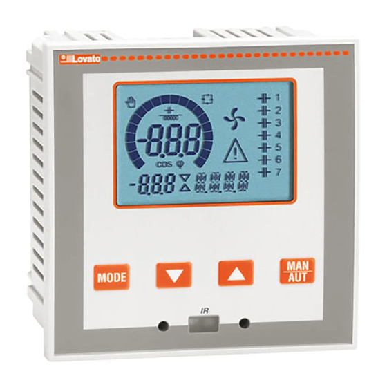
Page 2: Descriere
Backlit LCD screen. Versiuni: Versions: DCRL3 cu 3 relee, extensibil până la 5 max. DCRL3 with 3 relays, expandable to 5 max. DCRL5 cu 5 relee, extensibil până la 7 max. DCRL5 with 5 relays, expandable to 7 max. -
Page 3: Moduri De Operare
Moduri de operare Operating modes Există trei moduri de operare posibile, listate mai jos: There are three possible operating modes, listed below: Modul TEST TEST Mode Dacă unitatea este nouă şi nu a fost niciodată programată, aceasta When the unit is brand new and has never been programmed, it intră... -
Page 4: Măsuri
Măsuri Measures DCRL oferă o gamă de măsurători prezentate pe afişajul alfanumeric, The DCRL provides a set of measurements displayed on the împreună cu valoarea cosphi actuală, care este întotdeauna indicată alphanumeric display, in conjunction with the current cosphi that is pe afişajul principal. -
Page 5: Blocare Tastatură
Blocare tastatură Keypad lock Poate fi activată o funcţie pentru a exclude toate modificările A function to exclude all modification to operating parameters can be parametrilor de operare; vizualizarea măsurătorii încă este furnizată, în enabled; measurement viewing is still provided in any case. orice caz. -
Page 6: Portul De Programare Ir
Portul de programare IR IR programming port Parametrii DCRL pot fi configuraţi prin portul optic frontal, utilizând The parameters of the DCRL can be configured through the front modulul dongle de programare CX01 cu cod IR-USB sau modulul optical port, using the IR-USB code CX01 programming dongle, or with dongle CX02 cu cod IR-WiFi. -
Page 7: Rapid Ct Setup
Următorul tabel prezintă sub-meniurile disponibile: The following table lists the available submenus: Descriere Description Acces la Meniul de bază Access to Base menu Acces la Meniul avansat Accesso to Advanced menu Acces la Meniul alarmelor Accesso to Alarm menu Acces la Meniul comenzilor Access to Command menu Acces la Meniul de personalizare... -
Page 8: Configurare Ct Rapidă
Configurare CT rapidă Rapid CT set-up Când valoarea CT nu este cunoscută şi este utilizată numai la When the CT value is not known and only used at the moment of the momentul instalării, parametrul P.01 pentru CT primar poate rămâne installation, the P.01 parameter for CT primary can remain set at OFF setat la OFF, în timp ce celelalte pot fi programate. - Page 9 P.20 Limba mesajelor de P.20 Alarm messages language alarmă P.01 - Valoarea transformatorului de curent primar. Exemplu: cu CT 800/5 setare P.01 - The value of the primary current transformer. Example: with CT 800/5 set 800. Dacă este setat la OFF, după pornire, dispozitivul vă va solicita să setaţi CT şi 800.
- Page 10 P.29 Valoare de referință cos OFF / P.29 Cogeneration cos OFF / 0.50 IND – 0.50 0.50 IND – 0.50 cogenerare setpoint P.30 Sensibilitate deconectare OFF / 1 – 600 P.30 Disconnection sensitivity OFF / 1 – 600 P.31 Deconectarea pasului trece OFF Dezactivat P.31 Step disconnection passing OFF Disabled...
- Page 11 P.28 - Selectarea modului de introducere a paşilor. P.28 - Selecting mode of steps insertion. Mod standard - Operare normală cu selectarea liberă a paşilor Standard mode - Normal operation with free selection of the steps Mod liniar - paşii sunt conectaţi progresiv de la stânga spre dreapta, Linear mode - the steps are connected in progression from left towards urmând numai numărul paşilor şi în conformitate cu logica LIFO (Last In, right only following the step number and according to the LIFO (Last In...
-
Page 12: Alarme
P.61 - Activează alarma A01 şi defineşte comportamentul controlerului când P.61 - Enable alarm A01 and defines the behavior of the controller when the alarm alarma este activă: is active: OFF - Alarmă dezactivată OFF - Alarm disabled ON - Alarmă activată, numai vizual ON - Alarm enabled, only visual ALA - Alarmă... -
Page 13: Proprietăţi Implicite Alarme
Proprietăţi implicite alarme Default alarm properties Descriere Description Sub-compensare ● ● 15 min Undercompensation ● ● 15 min Supra-compensare ● 120 s Overcompensation ● 120 s Curent prea mic ● ● Current too low ● ● Curent prea mare ● 120 s Current too high ●... -
Page 14: Meniul Comenzilor
Meniul comenzilor Commands menu Meniul comenzilor permite executarea unor operaţiuni ocazionale cum ar The commands menu allows executing some occasional operations like reading fi resetarea vârfurilor de citire, golirea contoarelor, resetarea alarmelor peaks resetting, counters clearing, alarms reset, etc. etc. -
Page 15: Instalare
Utilizarea modulului dongle CX02 CX02 Dongle usage Modulul dongle CX02 oferă capabilitate de punct de acces WiFi pentru The CX02 dongle offers WiFi Access point capability for connection to PC, Tablet conexiune la PC, tabletă sau smartphone-uri. În plus, acesta oferă şi or smartphones. - Page 16 Instalare Installation DCRL este conceput pentru instalare încastrată. Cu montarea corectă, DCRL is designed for flush-mount installation. With proper mounting, it acesta garantează protecţie frontală de gradul IP54. guarantees IP54 front protection. Din interiorul panoului, pentru fiecare patru cleme de fixare, poziţionaţi ...
-
Page 17: Dispunere Borne
Cablaj monofazic Single-phase wiring CONEXIUNE MONOFAZICĂ SINGLE-PHASE CONNECTION Configuraţie cablaj pentru aplicaţii monofazate Wiring configuration for single-phase applications Măsură tensiune 1 citire de tensiune fază L1-N Voltage measure 1 phase voltage reading L1-N Măsură curent Fază L1 Current measure L1 phase Deviere unghi fază... -
Page 18: Istoric De Revizii Ale Manualului
Poziţia bornelor Terminals position DCRL3 DCRL5 Aux supply Aux supply 100-440V~ 100-440V~ 50/60Hz 50/60Hz 3,5 W 3,5 W 9,5 VA 9,5 VA V Input V Input 100-600V~ 100-600V~ 50/60Hz 50/60Hz Dimensiunile mecanice şi decuparea în panoul frontal (mm) Mechanical dimensions and front panel cutout (mm) - Page 19 0,5% f.s. 1 unitate Line voltage 0.5% f.s. 1digit Ieşire releu: DCRL3 OUT 1 - 2/DCRL5 OUT 1 - 4 Relay output: DCRL3 OUT 1 - 2 / DCRL5 OUT 1 - 4 Tip contact Contact type DCRL3 2 x 1 NO + contact comun...
Need help?
Do you have a question about the DCRL3 and is the answer not in the manual?
Questions and answers