Table of Contents
Advertisement
Quick Links
UWAGA!
● Należy uważnie przeczytać instrukcję przed instalacją lub użytkowaniem.
● By uniknąć zniszczeń lub zagrożenia życia urządzenia powinny
być instalowane przez wykwalifikowany personel w zgodzie z obowiązującymi
standardami.
● Przed pracami serwisowymi, należy odłączyć wszystkie napięcia od wejść pomiarowych i zasilania
pomocniczego oraz zewrzeć zaciski przekładnika prądowego.
● Produkty zaprezentowane w poniższym dokumencie mogą zostać zmienione lub ulepszone bez konieczności
wcześniejszego informowania o tym.
● Dane techniczne oraz opisy oddają w jak najdokładniejszy sposób posiadaną przez nas wiedzę, jednak
nie bierzemy odpowiedzialności za ewentualne błędy, braki oraz sytuacje awaryjne.
● W układzie należy zamontować rozłącznik (wyłącznik), który musi znajdować się niedaleko urządzenia
i być łatwo dostępny dla operatora. Musi spełniać wymogi następujących norm: IEC/ EN 61010-1 § 6.12.2.1.
● Należy czyścić urządzenie delikatną suchą szmatką, nie należy używać środków ściernych, płynnych
detergentów lub rozpuszczalników.
Spis treści
Wprowadzenie
Opis
Funkcje przycisków
Wskaźniki LED
Tryby pracy
Zasilanie
Menu główne
Hasło dostępu
Nawigacja po wyświetlanych stronach
Tabela wyświetlanych stron
Strona analizy harmonicznych
Strona przebiegów
Strony użytkownika
Wejścia, wyjścia, wewnętrzne zmienne, liczniki
Progi limitów
Zmienne kontrolowane zdalnie
Alarmy użytkownika
Logika PLC
Automatyczny test
CANbus
Port podczerwieni IR do programowania
Ustawianie parametrów przez PC
Ustawianie parametrów przez panel przedni
Tabela parametrów
Alarmy
Właściwości alarmów
Tabela alarmów
Opis alarmów
Tabela funkcji wejść
Tabela funkcji wyjść
Menu komend
Instalacja
Schematy podłączenia
Opis zacisków
Wymiary mechaniczne
Otwór montażowy
Dane techniczne
Historia wersji oprogramowania
Doc: I335PLGB0312_RGK700_RGK700SA
RGK700
RGK700SA
Sterownik agregatów
prądotwórczych
INSTRUKCJA OBSŁUGI
Strona
2
2
3
3
4
4
5
5
6
6
9
9
9
10
10
11
11
11
12
12
14
14
15
16
28
29
29
31
33
34
35
36
37
39
39
40
41
42
PL
RGK700
RGK700SA
Generating set
control unit
INSTRUCTIONS MANUAL
WARNING!
Carefully read the manual before the installation or use.
This equipment is to be installed by qualified personnel, complying to current
standards, to avoid damages or safety hazards.
● Before any maintenance operation on the device, remove all the voltages from measuring and supply
inputs and short-circuit the CT input terminals.
● Products illustrated herein are subject to alteration and changes without prior notice.
● Technical data and descriptions in the documentation are accurate, to the best of our knowledge, but no
liabilities for errors, omissions or contingencies arising there from are accepted.
● A circuit breaker must be included in the electrical installation of the building. It must be installed close by
the equipment and within easy reach of the operator.
It must be marked as the disconnecting device of the equipment:
IEC /EN 61010-1 § 6.12.2.1.
● Clean the instrument with a soft dry cloth; do not use abrasives, liquid detergents or solvents.
Index
Introduction
Description
Keyboard functions
Front LED indication
Operating modes
Power-up
Main menu
Password access
Display page navigation
Table of display pages
Harmonic analysis page
Waveform pages
User pages
Inputs, outputs, internal variables, counters
Limit thresholds
Remote-controlled variables
User alarms
PLC Logic
Automatic test
CAN bus
IR programming port
Parameter setting through PC
Setting of parameters (setup) from front panel
Parameter table
Alarms
Alarm properties
Alarm table
Alarm description
Input function table
Output function table
Command menu
Installation
Wiring diagrams
Terminal arrangement
Mechanical dimensions
Panel protection
Technical carachteristics
Manual revision history
24/03/2011
Page
2
2
3
3
4
4
5
5
6
6
9
9
9
10
10
11
11
11
12
12
14
14
15
16
28
29
29
31
33
34
35
36
37
39
39
40
41
42
s. 1 / 44
Advertisement
Table of Contents

Related Manuals for Lovato RGK700


Summary of Contents for Lovato RGK700
- Page 1 RGK700 RGK700 RGK700SA RGK700SA Sterownik agregatów Generating set prądotwórczych control unit INSTRUKCJA OBSŁUGI INSTRUCTIONS MANUAL UWAGA! WARNING! Carefully read the manual before the installation or use. ● Należy uważnie przeczytać instrukcję przed instalacją lub użytkowaniem. This equipment is to be installed by qualified personnel, complying to current ●...
-
Page 2: Wprowadzenie
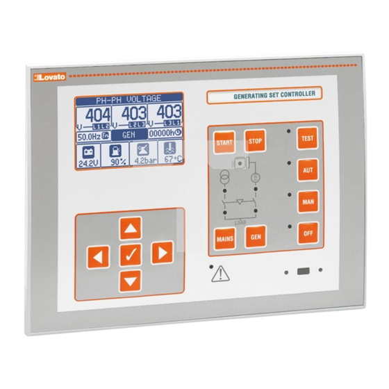
Built with dedicated components and extremely compact, łączy w sobie nowoczesne wykonanie panelu przedniego oraz wyświetlacz the RGK700 combines the modern design of the front panel with LCD zapewniający czytelne oczyty i intuicyjny interfejs użytkownika. practical installation and LCD screen that provides a clear and intuitive user interface. -
Page 3: Wskaźniki Led
Engine running LED (green) – Indicates the engine is running. The pracuje. RGK700 wykrywa status pracującego silnika na podstawie kilku RGK700 detects the state of the engine running on the basis of several sygnałów (napięcie/częstotliwość agregatu, D+, AC, W, czujnik). Dioda signals (generator voltage/frequency, D+, AC, W, Pick-up, etc.). -
Page 4: Tryby Pracy
There is normally no load procedurą rozruchu automatycznego. Sterownik nie dokonuje przełączenia switching. If there is a mains outage while the RGK700 is in TEST mode, obciążenia. W przypadku, gdy RGK700 jest w trybie TEST a wystąpią... -
Page 5: Zasilanie
błędy sieci to obciążenie jest przełączane do agregatu. Jeśli napięcie sieci load with remain switched to the generator until the operating mode is powróci w granice limitów to obciążenie pozostaje podłączone do agregatu changed. do czasu zmiany trybu pracy. Zasilanie Power-up ... -
Page 6: Nawigacja Po Wyświetlanych Stronach
Na niektórych stronach RGK700 istnieje możliwość przełączania, przy On some pages of the RGK700, the display can be switched from the użyciu przycisku ◄, pomiędzy wizualizacją pomiarów sieci i wizualizacją mains measurements to the generator measurements and vice versa pomiarów agregatu i na odwrót. -
Page 7: Tabela Wyświetlanych Stron
Key ◄ między między switches switches wskazaniami siecią a between between całkowitymi Total/Partial agregatem Mains and ◄ indications Generator częściowymi (RGK700) (RGK700) ► Podsumowanie Summary of electrical parametrów measurements Wskaźnik Mains/Gen. Phase Wskaźnik elektrycznych Ind. indication siec /agregat Wartości Measurements Wskaźnik... - Page 8 Autonomia paliwa Fuel autonomy Present fuel Autonomia Aktualne Residual rate from przy zużycie autonomy aktualnym paliwa with present zużyciu z CAN fuel rate z CAN from CAN Maximum Autonomia Maksymalne Residual declared przy zużycie autonomy engine fuel maksymalnym paliwa with rate zużyciu maximum...
-
Page 9: Strona Analizy Harmonicznych
Harmonic analysis page Sterownik RGK700 posiada funkcję analizy harmonicznych do 31 In the RGK700 it is possible to enable the calculation of the FFT w kolejności dla poniższych pomiarów: harmonic analysis up to the 31st order of the following measurements: Napięcia międzyfazowe... -
Page 10: Strony Użytkownika
Każda z tych stron może wyświetlać trzy pomiary, dowolnie wybrane Each of these pages can view 3 measurements, freely chosen among the z dostępnych w sterowniku RGK700. available readings of the RGK700. Tytuł strony może być zaprogramowany przez użytkownika. -
Page 11: Progi Limitów
Poniższa tabela pokazuje wszystkie wej/wyj i zmienne wewnętrzne The following table groups all the I/O and the internal variables managed dostępne w RGK700. by the RGK700. KOD. -
Page 12: Zmienne Kontrolowane Zdalnie
Istnieje możliwość wprowadzenia do logiki wszystkich zmiennych You can enter all the variables managed by the RGK700 in the program zarządzanych przez RGK700, takich jak wejścia (INPx), progi limitów logic, such as inputs (INPx), limit thresholds (LIMx), remote variables (LIMx), zmienne zdalne (REMx), statusy sterownika (RALx), itp. -
Page 13: Automatyczny Test
(PLCx) which can then be used to control the być następnie używane do kontroli wyjść RGK700 lub jako wsparcie outputs of the RGK700, or as backup memories to build a more complex do budowania bardziej skomplikowanych działań logicznych lub jako logic, or also to control user-defined alarms (UAx). - Page 14 In the case of a fault, this is indicated on the jest wystąpienie wielu kodów. W przypadku wystąpienia anomalii display of the RGK700 with both a code and with a description in the to wyświetlana jest ona na ekranie RGK700 z kodem i opisem related language, in the last of the sub-pages dedicated to the CAN.
-
Page 15: Port Podczerwieni Ir Do Programowania
IR programming port Parametry RGK700 można ustawiać przez optyczny port podczerwieni The parameters of the RGK700 can be configured through the front umiejscowiony na panelu przednim przy użyciu klucza USB-IR o kodzie optical port, using the IR-USB CX01 programming dongle, or with the IR- CX01 lub klucza WiFi o kodzie CX02. -
Page 16: Ustawianie Parametrów Przez Panel Przedni
Ustawianie parametrów przez panel przedni Parameter setting (setup) from front panel By otworzyć menu ustawień parametrów (setup): To open the parameters programming menu (setup): Należy przełączyć jednostkę w tryb OFF. turn the unit in OFF mode Przy normalnym wyświetlaniu pomiarów, należy wcisnąć przycisk in normal measurements view, press ... -
Page 17: Tabela Parametrów
N.B.: a backup copy of the setup data (settings that can be modified using 2 minuty, sterownik wyjdzie z menu ustawień automatycznie i powróci the keyboard) can be saved in the eeprom memory of the RGK700. This do normalnej pracy bez zapisania zmian wprowadzonych w ustawieniach data can be restored when necessary in the work memory. -
Page 18: Alarmy
P01.08 – Opóźnienie powrótu do wyświetlania strony domyślnej, od kiedy żaden z przycisków P01.08 – Default page display restore delay when no key pressed. If set to OFF the display nie został wcisnięty. Jeśli ustawiony na OFF na ekranie będze wyświetlana cały czas will always show the last page selected manually. - Page 19 P05.02 – Wybór progu zadziałania dla alarmu napięcia maksymalnego. P05.02 - Battery MAX. voltage alarm intervention threshold. P05.03 – Wybór progu zadziałania dla alarmu napięcia minimalnego. P05.03 - Battery MIN. voltage alarm intervention threshold. P05.04 – Opóźnienie zadziałania dla alarmów napięcia MIN i MAX. P05.04 - Battery MIN.
- Page 20 skompensować długość przewodu. Ta wartość może być również ustawiona bez without opening setup by using the quick function in the commands menu which lets wchodzenia do ustawień przy użyciu funkcji w menu komend, która pozwala na you view the measurements while calibrating. wyświetlenie pomiarów podczas ich kalibracji.
- Page 21 i dla alarmu. Zobacz odpowiednie alarmy. P10.09 - The fuel filling pump starts when the fuel drops below this level. P10.09 – Pompa napełniająca zaczyna pracować, gdy poziom paliwa spadnie poniżej P10.10 - The fuel filling pump stops when the fuel reaches or is higher than this level. tej wartości.
- Page 22 do agregatu. Próg temperatury = cykl wychładania uruchamiany jest tylko wtedy the generator and when the engine actually stops. gdy temperatura silnika przekroczy próg ustawiony w kolejnych parametrach. P11.19 – Temperature below which cooling is stopped. P11.18 – Maksymalny czas trwania cyklu wychładzania. Na przykład: czas pomiędzy P11.20 - Programmed output energizing time with stop magnets function.
- Page 23 P13.12 – Min. frequency intervention delay. P13.13 – OFF = kontrola sieci wyłączona INT = sieć kontrolowana przez sterownik RGK800. P13.13 – OFF = Mains control disabled. INT = Mains controlled by RGK700. EXT = kontrola sieci wykonywana przez urządzenie zewnętrzne. Wykorzystuje EXT = Mains controlled by external device.
- Page 24 P14.12 – Min. frequency intervention delay. P14.13 – OFF = kontrola agregatu wyłączona INT = agregat kontrolowany przez sterownik P14.13 – OFF = Generator control disabled. INT = Generator controlled by RGK700. EXT = RGK800. EXT = kontrola agregatu wykonywana przez urządzenie zewnętrzne.
-
Page 25: Tabela Funkcji Wejść
Note: This menu is divided into 6 sections that refer to 6 possible digital inputs możliwych wejść cyfrowych INP1…INP6, które mogą być zarządzane przez INP1…INP6, which can be managed by the RGK700. RGK700 P18.n.1 – Selects the functions of the selected input (see programmable inputs functions P18.n.1 –... - Page 26 P21.01 - Selects the type of engine ECU. If the ECU you wish to use can't be found in the list Generic J1939. W tym przypadku sterownik RGK700 będzie analizował wiadomości of possible choices, select Generic J1939. In this case, the RGK700 only analyses wysłane według standardów SAE J1939.
- Page 27 Zobacz poprzedni parametr. P23.07 - Type of connection between RGK700 and RGKRR relay remote unit. OFF = P23.07 – Typ podłączenia między RGK700 a RGKRR. OFF = komunikacja wyłączona. OUT= Communication disabled. OUT= Communication through programmable output set Komunikacja przez programowalne wyjście ustawione na funkcję...
-
Page 28: Menu Komend
For example, if this parameter is programmed for O+M, the zapobiegnie zamknięciu i w konsekwencji wygeneruje alarm A41 Anomalie stycznika Operating mode output will be enabled when the RGK700 is in OFF or MAN mode. sieci, silnik zostanie uruchomiony a obciążenie przełączone do agregatu. - Page 29 RGK700. kWh M = energia czynna sieci. kWh G = energia managed by the RGK700. kWh M = Mains active energy. kWh G = Generator active czynna agregatu. Kvarh M = energia bierna sieci. Kvarh G = energia bierna energy.
- Page 30 Jeśli nie można skasować alarmu oznacza to, iż należy usunąć be solved. przyczynę alarmu. In the case of one or more alarms, the behaviour of the RGK700 depends W przypadku pojawienia się kilku alarmów, RGK700 zareaguje według on the properties settings of the active alarms.
- Page 31 Tabela alarmów Alarm table OPIS DOMYSLNE WŁAŚCIWOŚCI ALAR. DESCRIPTION DEFAULT ALARM PROPERTIES Ostrzeżenie, temperatura silnika Engine temperature warning ● ● ● ● ● ● ● ● (czujnik analogowy) (analog sensor) Wysoka temperatura silnika High engine temperature (analog ● ● ● ●...
- Page 32 Anomalia stycznika sieci Mains contactor anomaly ● ● ● ● ● ● ● ● ● ● ● ● Wymagany serwis 1 Maintenance request 1 ● ● ● ● ● ● ● ● ● ● Wymagany serwis 2 Maintenance request 2 ●...
- Page 33 Błąd cyfrowego czujnika Przy zatrzymanym silniku dłużej niż minutę, Digital pressure sensor Engine stopped for over one minute, but oil ciśnienia czujnik ciśnienia oleju nie jest zamknięty, co fault sensor failed to close on no pressure signal. powoduje założenie, iż brak jest ciśnienia. Presumed break in connection.
- Page 34 Maintenance request 3 Wymagany serwis 3 System error RGK700 internal error. SeeSystem errors Błąd systemu Błąd wewnętrzny RGK700. Zobacz rozdział Błędy chapter for possible solutions. systemu w celu uzyskania możliwego rozwiązania. Tank too empty The relevant programmable input signals tank Zbiornik zbyt pusty Odpowiednie programowalne wejście sygnalizuje...
- Page 35 Woda w paliwie Alarm generowany, gdy sygnał zestyku wskazuje Water in fuel Alarm generated when the contact signals wodę w paliwie. Generowany przez wejście 'water in fuel'. Generated by digital input or cyfrowe lub wiadomość diagnostyczną CAN. CAN diagnostics message. Fuel filling pump failure Alarm generated when the fuel level in the Błąd pompy napełniającej...
- Page 36 Zbiornik pusty Zbiornik jest zbyt pusty. Otwarty zestyk generuje alarm A46. Tank empty Tank too empty. Generates the alarm A46 with an open Pompa napełniająca jest zatrzymywana. Może pracować contact. The filling pump is stopped. niezależnie, jako start-stop. Can function independently of start-stop. Początek napełniania Czujnik niskiego poziomu paliwa w zbiorniku.
- Page 37 Pobudzane, gdy trwa cykl wychładzania. Generator ready Indicates the RGK700 is in automatic mode and there are Agregat gotowy Wskazuje, że RGK700 jest w trybie AUT i nie ma żadnych no active alarms. aktywnych alarmów. Preheating valve Controls the fuel preheating valve See description of Zawór podgrzewania...
- Page 38 Instalacja Installation RGK700 jest dedykowany do montażu tablicowego. Przy właściwym RGK700 is designed for flush-mount installation. With proper mounting, it montażu zapewnia, od strony panelu przedniego, stopień ochrony IP65. guarantees IP65 front protection. Należy umieścić urządzenie w otworze montażowym; należy upewnić...
- Page 39 Należy wykonać tę samą operację dla czterech klipsów montażowych. Repeat the same operation for the four clips. Należy dokręcać wkręty z maksymalną siłą momentu obrotowego 0,5Nm Tighten the fixing screw with a maximum torque of 0,5Nm. ...
- Page 40 The CANbus connection has two 120-Ohm termination resistors at both na obu końcach szyny. By podłączyć rezystor wbdowany w sterownik ends of the bus. To connect the resistor incorporated in the RGK700 RGK700 należy połączyć zaciski TR i CAN-L. board, jumper TR and CAN-L.
-
Page 41: Wymiary Mechaniczne
Rozkład zacisków Terminals position SIEC PRĄD WYJ 9 WYJ 10 RS232 BATERIA 51 52 Wymiary mechaniczne (mm) Mechanical dimensions (mm) Doc: I335PLGB0312_RGK700_RGK700SA 24/03/2011 s. 41 / 44... -
Page 42: Otwór Montażowy
Otwór montażowy (mm) Front panel protection (mm) Doc: I335PLGB0312_RGK700_RGK700SA 24/03/2011 s. 42 / 44... -
Page 43: Dane Techniczne
Dane techniczne Technical characteristics Zasilanie pomocnicze Supply Napięcie akumulatora 12 lub 24VDC (dowolne) Battery rated voltage 12 or 24VDC indifferently Maksymalny pobór prądu 400mA przy 12VDC i 200mA przy Maximum current consumption 400mA at 12VDC e 200mA at 24VDC 24VDC Moc maksymalna: pobór / rozproszenie 4,8W Maximum power consumption/dissipation... -
Page 44: Canbu
Wyjście przekaźnikowe OUT 8 (beznapięciowe) Relay output OUT 8 (voltage free) Typ zestyku 1 przełączny (C/O) Contact type 1 changeover Wg UL B300 UL Rating B300 30V= 1A (pomocniczo) 30V= 1A Pilot Duty Napięcie pracy 250V~ Rated voltage 250V~ Prąd znamionowy przy 250VAC 8A w AC1 (1,5A w AC15) Rated current at 250VAC 8A AC1 (1,5A AC15)
Need help?
Do you have a question about the RGK700 and is the answer not in the manual?
Questions and answers