Table of Contents
Advertisement
Quick Links
ATTENTION !
● Lire attentivement le manuel avant toute utilisation et installation.
● Ces appareils doivent être installés par un personnel qualifié,
conformément aux normes en vigueur en matière d'installations, afin
d'éviter de causer des dommages à des personnes ou choses.
● Avant toute intervention sur l'instrument, mettre les entrées de mesure et d'alimentation hors
tension et court-circuiter les transformateurs de courant.
● Le constructeur n'assume aucune responsabilité quant à la sécurité électrique en cas
d'utilisation impropre du dispositif.
● Les produits décrits dans ce document sont susceptibles d'évoluer ou de subir des
modifications à n'importe quel moment. Les descriptions et caractéristiques techniques du
catalogue ne peuvent donc avoir aucune valeur contractuelle.
● Un interrupteur ou disjoncteur doit être inclus dans l'installation électrique du bâtiment. Celui-ci
doit se trouver tout près de l'appareil et l'opérateur doit pouvoir y accéder facilement. Il doit être
marqué comme le dispositif d'interruption de l'appareil : IEC/ EN 61010-1 § 6.11.2.1.
● Nettoyer l'instrument avec un chiffon doux, ne pas utiliser de produits abrasifs, détergents
liquides ou solvants.
Table des matières
Introduction
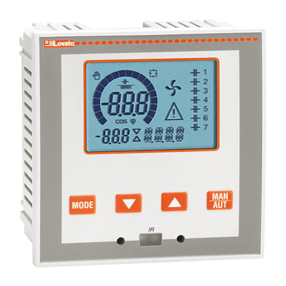
Le régulateur automatique de facteur de puissance DCRL a été conçu en
intégrant des fonctions avancées nécessaires aux applications de mise en
phase. Réalisé avec un boîtier dédié, aux dimensions très compactes, le
DCRL combine le design moderne de la partie frontale au montage
pratique et à la possibilité d'expansion sur la partie arrière, où un module
de la série EXP peut être inséré. L'écran LCD offre une interface claire et
intuitive à l'utilisateur.
Doc: MHIT100B1012_FR-GB.doc
FR
DCRL3 - DCRL5
Régulateur automatique
de facteur de puissance
MANUEL OPÉRATIONNEL
Page
1
2
2
2
3
4
5
5
6
6
6
6
7
8
12
12
13
14
15
16
16
18
18
18
19
GB
DCRL3 - DCRL5
Automatic Power Factor
Controller
INSTRUCTIONS MANUAL
WARNING!
x Carefully read the manual before the installation or use.
x This equipment is to be installed by qualified personnel, complying to
current standards, to avoid damages or safety hazards.
● Before any maintenance operation on the device, remove all the voltages from measuring
and supply inputs and short-circuit the CT input terminals.
● Products illustrated herein are subject to alteration and changes without prior notice.
● Technical data and descriptions in the documentation are accurate, to the best of our
knowledge, but no liabilities for errors, omissions or contingencies arising there from are
accepted.
● A circuit breaker must be included in the electrical installation of the building. It must be
installed close by the equipment and within easy reach of the operator.
It must be marked as the disconnecting device of the equipment:
IEC /EN 61010-1 § 6.11.2.1.
● Clean the instrument with a soft dry cloth; do not use abrasives, liquid detergents or
solvents
.
Index
Introduction
Description
Installation
Introduction
The DCRL automatic power factor control unit has been designed to offer
state-of-the-art functions for power factor compensation applications.
Built with dedicated components and extremely compact, the DCRL
combines the modern design of the front panel with practical installation
and the possibility of expansion from the rear, where one EXP series
module can be slotted. The LCD screen provides a clear and intuitive
user interface.
04/03/2014
Page
1
2
2
2
3
4
5
5
6
6
6
6
7
8
12
12
13
14
15
16
16
18
18
18
19
p. 1 / 19
Advertisement
Table of Contents

Subscribe to Our Youtube Channel
Related Manuals for Lovato DCRL3


Summary of Contents for Lovato DCRL3
-
Page 1: Table Of Contents
DCRL3 – DCRL5 DCRL3 – DCRL5 Régulateur automatique Automatic Power Factor de facteur de puissance Controller MANUEL OPÉRATIONNEL INSTRUCTIONS MANUAL ATTENTION ! WARNING! x Carefully read the manual before the installation or use. ● Lire attentivement le manuel avant toute utilisation et installation. -
Page 2: Description
Backlit LCD screen. x Versions : x Versions: DCRL3 avec 3 échelons, extensible jusqu'à 5 max. DCRL3 with 3 relays, expandable to 5 max. DCRL5 avec 5 échelons, extensible jusqu'à 7 max. DCRL5 with 5 relays, expandable to 7 max. -
Page 3: Modes De Fonctionnement
Modes de fonctionnement Operating modes Trois modes de fonctionnement sont possibles, voir ci-après : There are three possible operating modes, listed below: Mode TEST TEST Mode x Quand l'appareil sort de l'usine et n'a jamais été programmé, il entre x When the unit is brand new and has never been programmed, it automatiquement en mode TEST qui permet à... -
Page 4: Mesures
Mesures Measures x La DCRL fournit une série de mesures affichées sur l'écran x The DCRL provides a set of measurements displayed on the alphanumérique, associées au cos phi actuel qui reste toujours affiché alphanumeric display, in conjunction with the current cosphi that is sur l'écran principal. -
Page 5: Verrouillage Du Clavier
nCes valeurs ne sont affichées que si la fonction Ajustement puissance étape est n These measures are shown only if the Step trimming function is enabled autorisée (P.25=ON) et si le mot de passe avancé est autorisé et saisi. (P.25=ON) and the advanced password is enabled and entered. Verrouillage du clavier Keypad lock x Il est possible d'activer une fonction qui empêche de modifier les... -
Page 6: Port De Programmation Ir
Port de programmation IR IR programming port x La configuration des paramètres de la DCRL peut être effectuée via le x The parameters of the DCRL can be configured through the front port optique frontal, au moyen de la clé de programmation IR-USB optical port, using the IR-USB code CX01 programming dongle, or with code CX01 ou la clé... -
Page 7: Réglage Rapide Ta
x Les sous-menus disponibles sont énumérés dans le tableau suivant : The following table lists the available submenus: Code Description Description Accès au menu Base Access to Base menu Accès au menu Avancé Accesso to Advanced menu Accès au menu Alarmes Accesso to Alarm menu Accès au menu Commandes Access to Command menu... -
Page 8: Tableau Des Paramètres
Tableau des paramètres Parameter table x Tous les paramètres de programmation disponibles sont indiqués ci- x Below are listed all the programming parameters in tabular form. For each après sous forme de tableau. Pour chaque paramètre sont indiqués la parameter are indicated the possible setting range and factory default, as plage de réglage possible et le réglage d'usine par défaut, en plus de well as a brief explanation of the function of the parameter. - Page 9 P.01 – Valeur du primaire des transformateurs de courant. Exemple : avec TA P.01 - The value of the primary current transformer. Example: with CT 800/5 set 800/5 régler 800. Si réglé sur OFF, à la mise sous tension l'appareil demandera de 800.
- Page 10 P.32 Seuil alarme surcharge OFF / 100...150 P.32 Capacitor current overload OFF / 100...150 de courant alarm threshold condensateurs P.33 Capacitor overload OFF / 100.. 200 P.33 Seuil surcharge pour OFF / 100.. 200 immediate disconnection déconnexion immédiate threshold étape P.34 VT primary OFF / 50-50000 P.34...
- Page 11 P.28 – Sélection du mode d'insertion d'une étape. P.28 - Selecting mode of steps insertion. Standard – Fonctionnement normal avec sélection libre des étapes Standard mode - Normal operation with free selection of the steps Linéaire - les échelons sont uniquement insérés progressivement de la Linear mode - the steps are connected in progression from left towards gauche vers la droite en suivant le numéro de l'étape, pour être ensuite right only following the step number and according to the LIFO (Last In...
-
Page 12: Alarmes
P.97 Autorisation alarme A13 P.97 A13 Alarm enable DISC DISC P.98 Retard alarme A13 0-240 P.98 A13 alarm delay 0-240 P.99 Udm retard A13 P.99 A13 delay uom P.61 – Active l'alarme A01 et définit le comportement de l'unité électronique quand P.61 - Enable alarm A01 and defines the behavior of the controller when the alarm l'alarme est active : is active:... -
Page 13: Propriétés Par Défaut Des Alarmes
Micro interruption Si une micro interruption s'est No-Voltage release A no-voltage release has occoured on produite dans les entrées the line voltage inputs, lasting more voltamétriques pendant plus de 8 than 8ms. Voltage THD too high The THD of the plant voltage is higher THD tension trop Le THD de la tension de l'installation than the threshold set with P.43. -
Page 14: Menu Des Commandes
Menu des commandes Commands menu x Le menu des commandes permet d'effectuer des opérations x The commands menu allows executing some occasional operations like reading occasionnelles comme la mise à zéro de mesures, compteurs, alarmes, peaks resetting, counters clearing, alarms reset, etc. x If the Advanced level password has been entered, then the commands menu etc. -
Page 15: Utilisation Du Dongle Cx02
Utilisation du dongle CX02 CX02 Dongle usage x La clé (dongle) CX02, en plus de sa fonction de connexion WiFi à x The CX02 dongle offers WiFi Access point capability for connection to PC, Tablet l'ordinateur, tablette ou Smartphone, permet aussi de pouvoir mémoriser or smartphones. -
Page 16: Installation
Installation Installation x La DCRL est destinée à un montage encastré. Un montage correct x DCRL is designed for flush-mount installation. With proper mounting, it garantit la protection frontale IP54. guarantees IP54 front protection. x En procédant de l'intérieur du tableau, pour chacun des quatre clips de x From inside the panel, for each four of the fixing clips, position the clip in one of fixation, placer le clip dans l'un des deux guides latéraux en appuyant the two sliding guide, then press on the clip corner until the second guide snaps... - Page 17 Insertion connexion monophasée Single-phase wiring INSERTION CONNEXION MONOPHASÉE SINGLE-PHASE CONNECTION Configuration pour applications monophasées Wiring configuration for single-phase applications Mesure de tension 1 mesure de tension de phase L1-N Voltage measure 1 phase voltage reading L1-N Mesure de courant Phase L1 Current measure L1 phase Entre V (L1-N) et I (L1) Ö...
-
Page 18: Disposition Des Bornes
Disposition des bornes Terminals position DCRL3 DCRL5 Aux supply Aux supply 100-440V~ 100-440V~ 50/60Hz 50/60Hz 3,5 W 3,5 W 9,5 VA 9,5 VA V Input V Input 100-600V~ 100-600V~ 50/60Hz 50/60Hz Dimensions mécaniques et découpe du panneau (mm) Mechanical dimensions and front panel cutout (mm) Caractéristiques techniques... -
Page 19: Historique Des Révisions Du Manuel
Tension de ligne Line voltage Sorties de relais : DCRL3 OUT 1 - 2 / DCRL5 OUT 1 - 4 Relay output: DCRL3 OUT 1 - 2 / DCRL5 OUT 1 - 4 Type de contact Contact type...
Need help?
Do you have a question about the DCRL3 and is the answer not in the manual?
Questions and answers