Table of Contents
Advertisement
Quick Links
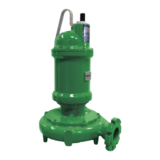
INSTALLATION and OPERATION MANUAL
Solids Handling Submersible Pump
#4 Frame
This product may be covered by one or more of the following patents and other patent(s) pending: US Patent 8,128,360
IMPORTANT!
Read all instructions in this manual before operating pump.
As a result of Crane Pumps & Systems, Inc., constant product improvement program,
product changes may occur. As such Crane Pumps & Systems reserves the right to
change product without prior written notification.
A Crane Co. Company
420 Third Street
Piqua, Ohio 45356
Phone: (937) 778-8947
Fax: (937) 773-7157
www.cranepumps.com
Series: 7365N
3VC
Vortex Pumps
20 - 50HP, 3450RPM
3VRA
Vortex Pumps
20 - 40HP, 3450RPM
4MM
Monovane Pumps
20 - 40HP, 1750RPM
4MB
Monovane Pumps
20 - 50HP, 1750RPM
4MH
Monovane Pumps
30 - 60HP, 1750RPM
4MHA
Monovane Pumps
20 - 25HP, 1150RPM
4DH
Dual Vane Pumps
20 - 60HP, 1750RPM
4VL
Vortex Pumps
20 - 40HP, 3450RPM
4VH
Vortex Pumps
20 - 50HP, 3450RPM
83 West Drive, Bramton
Ontario, Canada L6T 2J6
Phone: (905) 457-6223
Fax: (905) 457-2650
4VHA
Vortex Pumps
25 - 50HP, 3450RPM
6ML
Monovane Pumps
20 - 25HP, 1750RPM
6MM
Monovane Pumps
30 - 50HP, 1750RPM
6MH
Monovane Pumps
50 - 60HP, 1750RPM
20 - 25HP, 1150RPM
6DL
Dual Vane Pumps
20 - 30HP, 1750RPM
6D
Dual Vane Pumps
25 - 60HP, 1750RPM
20 - 40HP, 1150RPM
6V
Vortex Pumps
20 - 60HP, 1750RPM
20 - 30HP, 1150RPM
6VT
Vortex Pumps
20 - 30HP, 870RPM
Form No. 142695-Rev. P
8D
Dual Vane Pumps
25 - 60HP, 1750RPM
20 - 25HP, 1150RPM
10HP, 870RPM
8V
Vortex Pumps
25 - 60HP, 870RPM
8T
Tri Vane Pumps
60HP, 1750RPM
25 - 40HP, 1150RPM
10 - 30HP, 870RPM
10DL
Dual Vane Pumps
40HP, 1150RPM
15 - 30HP, 870RPM
10DH
Dual Vane Pumps
25 - 40HP, 1150RPM
10 - 25HP, 870RPM
10T
Tri Vane Pumps
60HP, 1750RPM
Advertisement
Table of Contents

Related Manuals for CRANE PUMPS & SYSTEMS 7365N Series


Summary of Contents for CRANE PUMPS & SYSTEMS 7365N Series
- Page 1 INSTALLATION and OPERATION MANUAL Solids Handling Submersible Pump Series: 7365N #4 Frame 4VHA Vortex Pumps Vortex Pumps Dual Vane Pumps 20 - 50HP, 3450RPM 25 - 50HP, 3450RPM 25 - 60HP, 1750RPM 20 - 25HP, 1150RPM 3VRA 10HP, 870RPM Vortex Pumps Monovane Pumps 20 - 40HP, 3450RPM 20 - 25HP, 1750RPM...
-
Page 2: Table Of Contents
TABLE OF CONTENTS SAFETY FIRST ..........................3 GENERAL INFORMATION ....................... 4 INSTALLATION .......................... 4 - 20 ELECTRICAL DATA ........................6 - 19 START-UP OPERATION ......................20 - 21 PREVENTATIVE MAINTENANCE ....................21 SERVICE and REPAIR ......................21 - 22 REPLACEMENT PARTS........................23 TROUBLE SHOOTING ........................ -
Page 3: Safety First
SAFETY FIRST! Please Read This Before Installing Or Operating Pump. This information is provided for SAFETY and to PREVENT Do not block or restrict discharge hose, as discharge EQUIPMENT PROBLEMS. To help recognize this information, hose may whip under pressure. observe the following symbols: IMPORTANT! Warns about hazards that can result WARNING! - DO NOT wear loose clothing that may... -
Page 4: General Information
SECTION A: GENERAL INFORMATION B-1.1) Submergence: It is recommended that the pump be operated at the minimum continuous duty submerged condition (See Fig. 1). A-1) To the Purchaser: The time required to draw the well down from top of motor Congratulations! You are the owner of one of the finest pumps to the minimum submergence level should not be greater on the market today. - Page 5 B-3) Liquid Level Controls: B-4.1) Electrical Connections: It is recommended to use a liquid level control system When the electrical connections are made, the lead wires that allows the on and off point to be separated by at least from the power cable should be stripped so that the ground twelve inches.
- Page 20 THREE PHASE 460-575 VOLT AC MOISTURE AND TEMPERATURE SENSORS MOISTURE AND TEMPERATURE SENSORS Power Cable Motor Lead ID Control Cable Control Cable Lead ID Lead ID Green (Ground) Green Brown P1 (Temperature Sensor) Black Yellow P2 (Temperature Sensor) Orange W1 (Moisture Sensor) White Blue W2 (Moisture Sensor)
- Page 21 WIRING DIAGRAM FIGURE 4 B-4.3) Overload Protection: Current sensing overloads must be provided in the pump A manual momentary start switch is required to prevent control panel and should be properly sized for the full load the automatic restarting of the motor when the thermostat current of the pump.
-
Page 22: Start-Up Operation
SECTION: C START-UP OPERATION TABLE 1 TEMPERATURE SENSOR ELECTRICAL RATINGS C-1) Check Voltage and Phase: Volts Continuous Inrush Before operating pump, compare the voltage and phase Amperes Amperes information stamped on the pump’s identification plate to the 110-120 3.00 30.0 available power. -
Page 23: Preventative Maintenance
C-3.2) Insulation Test: 2. Check oil for contamination using an oil tester with a range to 30 Kilovolts breakdown. Before the pump is put into service, an insulation (megger) 3. If oil is found to be clean and uncontaminated (measure test should be performed on the motor. - Page 24 E-2.2) Reassembly: Stationary Member (4A) Pol- To install impeller (6), apply a thin film of oil to motor shaft ished Face Out and slide impeller straight onto shaft, keeping keyways lined up. Drive key (7) into keyway. Thread cap screw (8) and washer (8A) into shaft and torque to 45 ft.
-
Page 25: Replacement Parts
SECTION: F REPLACEMENT PARTS F-1 ORDERING REPLACEMENT PARTS: When ordering replacement parts, ALWAYS furnish the following information: 1. Pump serial number and date code. (Paragraph F-4) 2. Pump model number. (Paragraph F-3) 3. Pump part number. (Paragraph F-2) 4. Part description. 5. -
Page 26: Trouble Shooting
TROUBLE SHOOTING CAUTION ! Always disconnect the pump from the electrical power source before handling. If the system fails to operate properly, carefully read instructions and perform maintenance recommendations. If operating problems persist, the following chart may be of assistance in identifying and correcting them: MATCH “CAUSE”... -
Page 27: Recommended Minimum Suction Clearance (Fig. 9)
DIM. ‘A’ MODEL INCHES NUMBER (MM) ACCESS COVER 4.50 (SUPPLIED BY OTHERS) (114) 3.50 (89) GUIDE RAIL CAP SUPPLIED WITH BAF MODELS 3VRA 4.25 (121) INTERMEDIATE SUPPORT ASSY 5.00 (OPTIONAL) REFER (127) TO SECTION C-3 2" PIPE GUIDE RAILS (SUPPLIED BY OTHERS) 5.20 (132) 4VHA... -
Page 28: Cross Sections (Fig. 10 & 11)(Before March-2016)
CROSS SECTIONS (Before March-2016) SH Vortex SH Enclosed FIGURE 10 FIGURE 11... -
Page 29: Exploded Views (Fig. 12) (Before March-2016)
EXPLODED VIEWS (Before March-2016) FIGURE 12... -
Page 30: Parts List
PARTS LIST (Before March-2016) ITEM PART NO. DESCRIPTION MATERIAL 127223 Screw, SHCS, M12 x 1.75 x 25, SS 18-8 SS 127248 Pin, Spring, .125 Dia. x .50” LG, SS 420 SS 129900 Seal, Mech-type 21, 1.875”, C/CE/B 129900SD Seal, Mech-type 21, 1.875”, SC/SC/B See Table Impeller, Vortex Ductile Iron... - Page 31 SH Pump 'Fixed' Cord Assemblies (Before March-2016) Length Part No. Cord Size Cord O.D. (feet) 130906XF 8/4 - 18/4 1.12in ± .02in (28.4mm ± .5mm) 130906XJ 8/4 - 18/4 1.12in ± .02in (28.4mm ± .5mm) 130906XL 8/4 - 18/4 1.12in ± .02in (28.4mm ± .5mm) 130907XF 6/4 - 18/4 1.14in ±...
-
Page 32: Cross Sections (Fig. 13 & 14)(After March-2016)
CROSS SECTIONS (After March-2016) SH Vortex SH Enclosed FIGURE 13 FIGURE 14... -
Page 33: Exploded Views (Fig. 15) (After March-2016)
EXPLODED VIEWS (After March-2016) FIGURE 15... -
Page 34: Parts List
PARTS LIST (After March-2016) ITEM PART NO. DESCRIPTION MATERIAL 127223 Screw, SHCS, M12 x 1.75 x 25 300 SS 127248 Pin, Spring, .125 Dia. x .50” LG, SS 420 SS 129900 Seal, Mech-type 21, 1.875” C/CE/B 129900SD Seal, Mech-type 21, 1.875” SC/SC/B See Table Impeller... - Page 35 SH Pump 'Plug and Play' (Removeable) Cord Assemblies (After March-2016) Length Part No. Cord Size Cord O.D. (feet) 138317XC 8/4 - 18/4 1.12in ± .02in (28.4mm ± .5mm) 138317XF 8/4 - 18/4 1.12in ± .02in (28.4mm ± .5mm) 138317XJ 8/4 - 18/4 1.12in ±...
- Page 36 Notes...
-
Page 37: Warranty
IMPORTANT! WARRANTY REGISTRATION IMPORTANT! Your product is covered by a warranty: WARRANTY REGISTRATION www.cranepumps.com/downloadables/CATALOGS_OIPMs/Warranty/24MonthWarranty.pdf To complete the Start-Up/ Warranty Registration Form go to: Your product is covered by the enclosed Warranty. https://www.cranepumps.com/ProductRegistration If you have a claim under the provisions of the warranty, contact your local If you have a claim under the provision of the warranty, contact your local Crane Pumps &...
Need help?
Do you have a question about the 7365N Series and is the answer not in the manual?
Questions and answers