Table of Contents
Advertisement
Quick Links
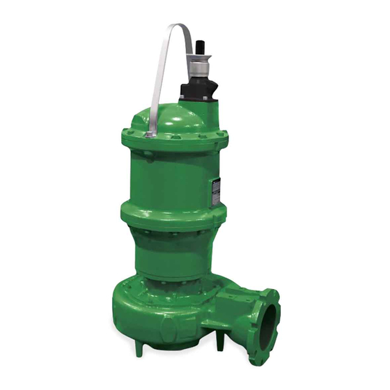
INSTALLATION and OPERATION MANUAL
Solids Handling Submersible Pump
#4 Frame
This product may be covered by one or more of the following patents and other patent(s) pending: US Patent 8,128,360
These pumps are classified as a Class I Division 1 Groups C&D Explosion-Proof by CSA to NEC and CEC specifications. Opening
the motor, including maintenance of the upper mechanical seal, must be performed by CP&S to maintain the certification. Internal
maintenance performed by non-certified personnel will void the explosion-proof rating
IMPORTANT!
Read all instructions in this manual before operating pump.
As a result of Crane Pumps & Systems, Inc., constant product improvement program,
product changes may occur. As such Crane Pumps & Systems reserves the right to
change product without prior written notification.
A Crane Co. Company
420 Third Street
Piqua, Ohio 45356
Phone: (937) 778-8947
Fax: (937) 773-7157
www.cranepumps.com
Manual Index
Series: 7365
3VRA
6ML
Vortex Pumps
Monovane Pumps
20 - 40HP, 3450RPM
20 - 25HP, 1750RPM
6MM
4MM
Monovane Pumps
Monovane Pumps
30 - 50HP, 1750RPM
20 - 40HP, 1750RPM
6MH
4MB
Monovane Pumps
Monovane Pumps
50 - 60HP, 1750RPM
20 - 50HP, 1750RPM
20 - 25HP, 1150RPM
4MH
6DL
Monovane Pumps
Dual Vane Pumps
30 - 60HP, 1750RPM
20 - 30HP, 1750RPM
4MHA
6D
Monovane Pumps
Dual Vane Pumps
20 - 25HP, 1150RPM
25 - 60HP, 1750RPM
4DH
20 - 40HP, 1150RPM
Dual Vane Pumps
6V
20 - 60HP, 1750RPM
Vortex Pumps
4VL
20 - 60HP, 1750RPM
Vortex Pumps
20 - 30HP, 1150RPM
20 - 40HP, 3450RPM
6VT
4VH
Vortex Pumps
Vortex Pumps
20 - 30HP, 870RPM
20 - 50HP, 3450RPM
8D
4VHA
Dual Vane Pumps
Vortex Pumps
25 - 60HP, 1750RPM
25 - 50HP, 3450RPM
20 - 25HP, 1150RPM
10HP, 870RPM
83 West Drive, Brampton
Ontario, Canada L6T 2J6
Phone: (905) 457-6223
Fax: (905) 457-2650
8V
Vortex Pumps
25 - 60HP, 870RPM
8T
Tri Vane Pumps
60HP, 1750RPM
25 - 40HP, 1150RPM
10 - 30HP, 870RPM
10DL
Dual Vane Pumps
40HP, 1150RPM
15 - 30HP, 870RPM
10DH
Dual Vane Pumps
25 - 40HP, 1150RPM
10 - 25HP, 870RPM
10T
Tri Vane Pumps
60HP, 1750RPM
25 - 40HP, 1150RPM
10 - 30HP, 870RPM
P.O. Box 174515
Jebel Ali, Dubai UAE
Phone: (971) 4-886-4949
Fax: (971) 4-886-4950
Form No. 133603-Rev. N
Advertisement
Table of Contents

Related Manuals for CRANE PUMPS & SYSTEMS DEMING 7365 Series


Summary of Contents for CRANE PUMPS & SYSTEMS DEMING 7365 Series
- Page 1 Manual Index INSTALLATION and OPERATION MANUAL Solids Handling Submersible Pump Series: 7365 #4 Frame 3VRA Vortex Pumps Monovane Pumps Vortex Pumps 20 - 40HP, 3450RPM 20 - 25HP, 1750RPM 25 - 60HP, 870RPM Monovane Pumps Tri Vane Pumps Monovane Pumps 30 - 50HP, 1750RPM 60HP, 1750RPM 20 - 40HP, 1750RPM...
-
Page 2: Table Of Contents
TABLE OF CONTENTS SAFETY FIRST ..........................3 GENERAL INFORMATION ....................... 4 INSTALLATION .......................... 4 - 20 ELECTRICAL DATA ........................6 - 20 START-UP OPERATION ........................21 PREVENTATIVE MAINTENANCE ....................22 SERVICE and REPAIR ......................22 - 23 REPLACEMENT PARTS........................24 TROUBLE SHOOTING ........................ -
Page 3: Safety First
SAFETY FIRST! Please Read This Before Installing Or Operating Pump. This information is provided for SAFETY and to PREVENT WARNING! - DO NOT wear loose clothing that may EQUIPMENT PROBLEMS. To help recognize this information, become entangled in the impeller or other moving parts. observe the following symbols: WARNING! - Keep clear of suction and discharge IMPORTANT! Warns about hazards that can result... -
Page 4: General Information
SECTION A: GENERAL INFORMATION B-1.1) Submergence: It is recommended that the pump be operated at the minimum continuous duty submerged condition (See Fig. 1). The A-1) To the Purchaser: time required to draw the well down from top of motor to Congratulations! You are the owner of one of the finest pumps the minimum submergence level should not be greater than on the market today. - Page 5 B-3) Liquid Level Controls: will ensure that if the cable is inadvertently pulled out of the It is recommended to use a liquid level control system connection point, the ground wire will be the last lead to break that allows the on and off point to be separated by at least the circuit.
- Page 19 THREE PHASE 460-575 VOLT AC THREE PHASE 460-575 VOLT AC MOISTURE AND TEMPERATURE SENSORS MOISTURE AND TEMPERATURE SENSORS Power Cable Power Cable Motor Lead ID Motor Lead ID Control Cable Control Cable Lead ID Lead ID Green (Ground) Green Brown P1 (Temperature Sensor) Black Yellow...
- Page 20 TYPICAL THERMAL PROTECTION WIRING DIAGRAM FIGURE 4 B-4.3) Overload Protection: B-4.4) Moisture Sensors: Current sensing overloads must be provided in the pump A normally open (N/O) detector is installed in the pump seal control panel and should be properly sized for the full load chamber, which will detect any moisture present, and a current of the pump.
-
Page 21: Start-Up Operation
FIGURE 5 It is advisable that all three phase control panels be purchased sensing probes in the motor is intact. This procedure should be from the factory. performed periodically to confirm integrity of the circuit. SECTION C: START-UP OPERATION C-3) Start-Up Report: Included at the end of this manual is one start-up report sheet, C-1) Check Voltage and Phase: this sheet is to be completed as applicable. -
Page 22: Preventative Maintenance
SECTION D: PREVENTATIVE MAINTENANCE IMPORTANT! - Do not overfill oil. Overfilling of seal chamber with oil can create excessive and dangerous As the motor and seal chamber are oil-filled, no lubrication or hydraulic pressure which can destroy the other maintenance is required, and generally Barnes Pumps pump and create a hazard. Overfilling oil will give very reliable service and can be expected to operate voids warranty. - Page 23 E-3) Outer Shaft Seal Service: Make sure the stationary member is in straight and that the rubber ring is not out of it’s groove. Lightly oil (DO NOT CAUTION ! - Handle seal parts with extreme care. DO use grease) shaft and inner surface of bellows on rotating NOT scratch or mar lapped surfaces.
-
Page 24: Replacement Parts
SECTION F: REPLACEMENT PARTS F-1) Ordering Replacement Parts: When ordering replacement parts, ALWAYS furnish the follow- ing information: 1. Pump serial number and date code. (Paragraph F-4) 2. Pump model number. (Paragraph F-3) 3. Pump part number. (Paragraph F-2) 4. Part description. 5. -
Page 25: Trouble Shooting
TROUBLE SHOOTING CAUTION ! Always disconnect the pump from the electrical power source before handling. If the system fails to operate properly, carefully read instructions and perform maintenance recommendations. If operating problems persist, the following chart may be of assistance in identifying and correcting them: MATCH “CAUSE”... -
Page 26: Recommended Minimum Suction Clearance (Fig. 9)
DIM. ‘A’ MODEL INCHES NUMBER (MM) ACCESS COVER (SUPPLIED BY OTHERS) 3.00 (76.2) GUIDE RAIL CAP SUPPLIED 3VRA WITH BAF MODELS 3.50 (88.9) INTERMEDIATE SUPPORT ASSY 3.75 (OPTIONAL) REFER (95.3) TO SECTION C-3 2" PIPE GUIDE RAILS (SUPPLIED BY OTHERS) 4.00 (101.6) 4VHA... -
Page 27: Cross Sections (Fig. 10 & 11)(Before March-2016)
CROSS SECTION (Before March-2016) IMPORTANT! - Service is limited to the following components becuase of the explosion proof rating: impeller, lower mechanical seal, volute and power cord. Service to any other components WILL VOID the warranty and explosion proof certification. Any further work required contact Crane Pumps & Systems. Vortex Enclosed FIGURE 10 FIGURE 11 Items Not Shown: 41, 42... -
Page 28: Exploded View (Fig. 12 & 13)(Before March-2016)
Exploded Views (Before March-2016) CORD ENTRY BOLTS TORQUE TO: 35 FT/LBS. MUST BE METAL TO METAL. CORD ENTRY BOLTS TORQUE TO: 35 FT/LBS. MUST BE METAL TO METAL. 3X - 6X TORQUE TO: 35 ± 1.4 FT/LBS. APPLY GREEN LOCTITE RC 603 8 8A TORQUE TO: APPLY GREEN... -
Page 29: Parts Lists (Before March-2016)
PARTS LIST (Before March-2016) ITEM PART NO. DESCRIPTION MATERIAL See Table Driver Assembly 127223 ♦ π ˃ Screw, SHCS, M12 x 1.75 x 25, SS 18-8 SS See Table ƒ Impeller, Vortex Ductile Iron Q21-20-J8 ♦ Key, ¼ x ¼ x 1½”, 303 SS 303 SS 136284 ♦... -
Page 30: Cross Sections (Fig. 14 & 15)(After March-2016)
CROSS SECTION (After March-2016) IMPORTANT! - Service is limited to the following components becuase of the explosion proof rating: impeller, lower mechanical seal, volute and power cord. Service to any other components WILL VOID the warranty and explosion proof certification. Any further work required contact Crane Pumps & Systems. Vortex Enclosed FIGURE 14 FIGURE 15 Items Not Shown: 61, 62... -
Page 31: Exploded View (Fig. 16 & 17)(After March-2016)
EXPLODED VIEWS (After March-2016) Vortex Enclosed FIGURE 16 FIGURE 17 Items Not Shown: 61, 62... -
Page 32: Parts Lists (After March-2016)
PARTS LIST (After March-2016) ITEM PART NO. DESCRIPTION MATERIAL See Table Driver Assemblies 127223 ♦ ˃ Screw, SHCS, M12 x 1.75 x 25 300 SS See Table ƒ Impeller Ductile Iron Q21-20-J8 ♦ Key, ¼ x ¼ x 1½”, 303 SS 303 SS 136284 ♦... - Page 33 Notes...
- Page 34 Notes...
- Page 35 Limited 24 Month Warranty Crane Pumps & Systems warrants that products of our manufacture will be free of defects in material and workmanship under normal use and service for twenty-four (24) months after manufacture date, when installed and maintained in accordance with our instructions.This warranty gives you specifi c legal rights, and there may also be other rights which vary from state to state.
-
Page 36: Warranty
IMPORTANT! WARRANTY INFORMATION Warranty will be voided if the product is serviced by any Unauthorized Service Center. IMPORTANT! WARRANTY REGISTRATION Your product is covered by the enclosed Warranty. To complete the Warranty Registration Form go to: http://www.cranepumps.com/ProductRegistration/ If you have a claim under the provision of the warranty, contact your local Crane Pumps &... -
Page 37: Start-Up Report
A Crane Co. Company START-UP REPORT General Information Pump Owner’s Name: __________________________________________________________ Address: ____________________________________________________________________ Location of Installation: _________________________________________________________ Contact Person: __________________________________Phone: _______________________ Purchased From: _____________________________________________________________ Nameplate Data Pump Model #: ___________________ Serial #: _____________________________________ Part #: __________________________ Impeller Diameter: ____________________________ Voltage: _________ Phase: _____ Ø... - Page 38 Submersible Pumps Resistance of cable and pump motor (measured at pump control): Red-Black:_______Ohms(Ω) Red-White:_______Ohms(Ω) White-Black:_______Ohms(Ω) Resistance of Ground Circuit between Control Panel and outside of pump: __________Ohms(Ω) MEG Ohms check of insulation: Red to Ground: _________ White to Ground: __________ Black to Ground: ____________ Operational Checks Is there noise or vibration present? YES___ NO___ Source of noise/vibration: ___________...
Need help?
Do you have a question about the DEMING 7365 Series and is the answer not in the manual?
Questions and answers