Table of Contents
Advertisement
Quick Links
GETTING STARTED GUIDE
NI RF Signal Generators
Contents
This guide explains how to install, configure, test, and begin
using NI RF signal generators. For more information, such as
NI RF signal generator features and programming, refer to the
NI RF Signal Generators Help, accessible at Start»All Programs»
National Instruments»NI-RFSG»Documentation.
Refer to the specifications document that ships with your device for
detailed specifications.
For the most current versions of documentation, visit
For the most current example programs, visit
For the latest version of NI-RFSG, visit
Conventions ............................................................................................ 2
1. Verifying System Requirements ......................................................... 4
2. Unpacking ........................................................................................... 4
3. Verifying Kit Contents........................................................................ 5
4. Installing the Software ........................................................................ 7
Installing Application Development Software ................................ 7
Installing the NI-RFSG Instrument Driver ...................................... 7
Installing Toolkits or Add-On Software .......................................... 7
5. Installing the Hardware ....................................................................... 8
PXI Modules .................................................................................... 8
NI 5670/5671 ............................................................................ 8
Installing PXI Modules............................................................. 8
PXI Express Modules ...................................................................... 10
NI 5672 ..................................................................................... 11
Cooling............................................................................................. 13
6. Interconnecting the NI 5670/5671/5672 Modules .............................. 14
7. Configuring NI RF Signal Generators in MAX.................................. 16
Configuring the NI 5670/5671/5672 in MAX ................................. 16
Rename Both Modules ............................................................. 17
Associate the Upconverter with the AWG Module.................. 18
ni.com/manuals
ni.com/instruments
.
ni.com/rf
.
.
Advertisement
Table of Contents

Related Manuals for National Instruments NI 5650


Summary of Contents for National Instruments NI 5650
-
Page 1: Table Of Contents
NI RF signal generators. For more information, such as NI RF signal generator features and programming, refer to the NI RF Signal Generators Help, accessible at Start»All Programs» National Instruments»NI-RFSG»Documentation. Refer to the specifications document that ships with your device for detailed specifications. -
Page 2: Conventions
Generator Test Panel ..............18 Configuring the NI 5650/5651/5652 in MAX........19 Rename the NI 5650/5651/5652 ..........20 Generate a Signal Using the NI 5650/5651/5652 RF Signal Generator Test Panel ..............20 8. Setting up Synchronization for NI-DAQmx Devices in MAX ...21 9. Programming the RF Signal Generator ..........21 NI-RFSG Instrument Driver.............22... - Page 3 Italic text also denotes text that is a placeholder for a word or value that you must supply. module Refers to the NI 5650/5651/5652 hardware or to one of the two hardware components of the NI 5670/5671/5672 RF signal generator: the AWG PXI/PXIe module or the upconverter module.
-
Page 4: Verifying System Requirements
NI-RFSG Instrument Driver Readme, which is available on the NI-RFSG CD. After you install NI-RFSG, you can access the NI-RFSG Instrument Driver Readme at Start»All Programs»National Instruments»NI-RFSG» Documentation. 2. Unpacking NI RF signal generator hardware modules ship in antistatic packages to prevent damage from electrostatic discharge (ESD). -
Page 5: Verifying Kit Contents
– Maintain Forced-Air Cooling Note to Users ❑ Either an NI 5670/5671/5672 or NI 5650/5651/5652 device. The components required for installing each device are described in Tables 1 and 2, respectively. All the components listed should be included in the kit unless otherwise noted. - Page 6 (optional, not included) 100 N-cm SMA torque wrench (not included) Part numbers on the NI PXI/PXIe-5421/5441/5442 modules vary according to memory size. Table 2. NI 5650/5651/5652 Required Parts Inventory and Replacement Part Numbers Hardware Component Replacement Part Number NI PXI-5650...
-
Page 7: Installing The Software
Toolkit add-on software in order to properly install the Modulation Toolkit examples for NI-RFSG. If the Modulation Toolkit is already installed, repeat or repair the Modulation Toolkit installation after installing NI-RFSG. © National Instruments Corporation NI RF Signal Generators Getting Started Guide... -
Page 8: Installing The Hardware
5. Installing the Hardware This section describes how to install hardware for PXI platforms. PXI Modules NI PXI modules are sensitive instruments that should be handled carefully. Do not expose the module to temperatures or humidity beyond the rated maximums. Keep the module free of dust by cleaning with compressed air only. - Page 9 Figure 1 shows the correct installation of a PXI module into a compatible chassis slot. 1 PXI Chassis 3 Ejector Handle in Down Position 2 NI PXI Module Figure 1. PXI Module Installation © National Instruments Corporation NI RF Signal Generators Getting Started Guide...
-
Page 10: Pxi Express Modules
After completing all the steps, continue with the procedure in section Interconnecting the NI 5670/5671/5672 Modules. Installing the NI 5650/5651/5652 Install the NI 5650/5651/5652 by completing steps 1 though 11 in the Installing PXI Modules section. After completing all the steps, continue with the procedure in the Configuring the NI 5650/5651/5652 in MAX section. - Page 11 SMA connectors must be connected and tightened before the SMB or AWG Caution connectors are mated in order to preserve cable life and reduce stress on the SMB connectors. © National Instruments Corporation NI RF Signal Generators Getting Started Guide...
- Page 12 Figure 3 and Figure 4 show the two possible slot configurations for the NI 5672 module in an 8-slot PXI Express chassis. NI PXIe-1062Q 1 System Controller Expansion Slots 5 PXI Express System Timing Slot 2 PXI Express System Controller Slot 6 NI PXI-5610 Module 3 PXI Peripheral Slots 7 NI PXIe-5442 Module...
-
Page 13: Cooling
When installing the hardware, refer to the guidelines in the Maintain Forced-Air Cooling Note to Users included with the NI RF signal generator to ensure that the device can cool itself effectively. © National Instruments Corporation NI RF Signal Generators Getting Started Guide... -
Page 14: Interconnecting The Ni 5670/5671/5672 Modules
♦ NI 5650/5651/5652 Under conditions of proper air flow and 25 °C (63 °F) ambient temperatures, the NI 5650/5651/5652 operates at internal temperatures of approximately 38 °C (100 °F). Hot Surface If the NI RF signal generator has been in use, it may exceed safe handling temperatures and cause burns. - Page 15 Incorrect torque at SMA connections can degrade signal fidelity, PLL performance, and insertion loss. Use an SMA torque wrench to ensure all SMA connections are properly torqued to 100 N-cm. © National Instruments Corporation NI RF Signal Generators Getting Started Guide...
-
Page 16: Configuring Ni Rf Signal Generators In Max
7. Configuring NI RF Signal Generators in MAX Use Measurement & Automation Explorer (MAX) to configure your National Instruments hardware. MAX informs other programs about which devices reside in the system and how they are configured. MAX is automatically installed with NI-RFSG. -
Page 17: Rename Both Modules
MXI documentation to ensure that the MXI interface is properly set up. Software optimization might be necessary. For MXI-3 optimization, select Start»All Programs»National Instruments MXI-3»MXI-3 Optimization. MXI-4 optimization is performed automatically by the MXI-4 hardware. -
Page 18: Associate The Upconverter With The Awg Module
Click OK. 10. Verify that the new names for both modules are displayed. Associate the Upconverter with the AWG Module You must create a MAX association between the NI 5610 upconverter module and the NI 5421/5441/5442 AWG module to control both hardware modules as a single NI RF signal generator. -
Page 19: Configuring The Ni 5650/5651/5652 In Max
MXI-4 optimization is performed automatically by the MXI-4 hardware. Perform a device self-test to verify installation by right-clicking the NI 5650/5651/5652 device and selecting Self-Test. A dialog box appears and indicates whether the device passed the test. When the self-test finishes, a message indicates either successful verification or an error. -
Page 20: Rename The Ni 5650/5651/5652
Rename the NI 5650/5651/5652 MAX allows you to rename the NI 5650/5651/5652 hardware module. The MAX name is used in software to operate the NI 5650/5651/5652 hardware resources. You do not have to change the module name from the default but doing so can make programming easier. -
Page 21: Setting Up Synchronization For Ni-Daqmx Devices In Max
Click Close to return to MAX. Exit MAX. You have completed setup, configuration, and testing of the NI 5650/5651/5652 RF Signal Generator. 8. Setting up Synchronization for NI-DAQmx Devices in MAX If you plan to share triggers or clocks to synchronize NI-DAQmx devices, you must identify or configure certain components in MAX. -
Page 22: Ni-Rfsg Instrument Driver
LabVIEW and/or LabWindows/CVI Application Development Environment NI-RFSG Instrument Driver NI 5670/5671/5672 NI 5650/5651/5652 RF Signal Generator Hardware Figure 7. RF Signal Generator Hardware-Software Architecture Refer to the NI RF Signal Generators Help for more information about NI RF signal Note generator hardware/software architecture. -
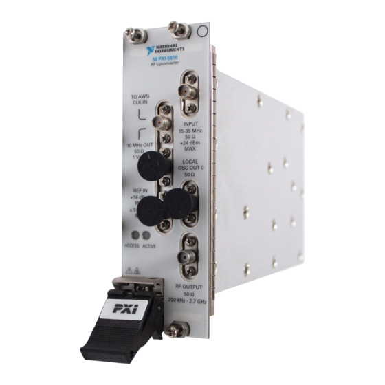
Page 23: Appendix A: Hardware Front Panel Connectors And Indicators
NI 5610 RF Upconverter Module The NI 5610 RF upconverter module front panel contains six connectors and two multicolor LEDs, as shown in Figure 8. Figure 8. NI 5610 Upconverter Module Front Panel © National Instruments Corporation NI RF Signal Generators Getting Started Guide... - Page 24 Table 3. NI 5610 RF Upconverter Module Front Panel Connectors Connector Purpose TO AWG CLK IN Output terminals for replications of the upconverter 10 MHz frequency reference signal, which is useful for driving other devices. Each 10 MHz OUT replication is 180° out-of-phase with the other. The output signal at these connectors is always on and cannot be disabled.
-
Page 25: Ni 5421/5441 Awg Module
Connect to the IF INPUT connector on the NI 5610 front panel. CLK IN Output terminal for the AWG module reference clock signal. Connect to the REF OUT connector on the NI 5610 module front panel. © National Instruments Corporation NI RF Signal Generators Getting Started Guide... - Page 26 Table 5. NI 5421/5441 AWG Module Front Panel Connectors (Continued) Connector Purpose PFI 0 Bidirectional SMB connectors. As an input, the PFI terminals can accept a trigger from an external source to start or step through signal generation. PFI 1 DIGITAL DATA &...
-
Page 27: Ni 5442 Awg Module
Connect to the REF OUT connector on the NI 5610 module front panel. PFI 0 Bidirectional SMB connectors. As an input, the PFI terminals can accept a trigger from an external source to start or step through signal generation. PFI 1 © National Instruments Corporation NI RF Signal Generators Getting Started Guide... - Page 28 Table 8. NI 5442 AWG Module Front Panel LEDs Indications ACCESS Indicates the basic hardware status of the NI 5442 AWG module. This LED functions identically to the ACCESS LED on the NI 5610 upconverter module front panel. OFF—The module is not yet functional or has detected a problem with a power rail.
-
Page 29: Ni 5650/5651/5652 Rf Signal Generator Module
IN/OUT IN 5 Vp-p MAX OUT 1 Vp-p Figure 11. NI 5650/5651/5652 RF Signal Generator Module Front Panel Table 9. NI 5650/5651/5652 RF Signal Generator Module Front Panel Connectors Connector Purpose RF OUT Output terminal for the RF signal at the requested frequency and power level. -
Page 30: Appendix B: Building A Basic Ni-Rfsg Application
Table 10. NI 5650/5651/5652 RF Signal Generator Module Front Panel LEDs Indications ACCESS Indicates the basic hardware status of the NI 5650/5651/5652 module. OFF—The module is not yet functional or has detected a problem with a PXI power rail. AMBER—The module is being accessed. - Page 31 Figure 14. Frequency and Power Level Terminals on the niRFSG Configure RF VI 10. Right-click each terminal and select Create»Control from the shortcut menu to create frequency and power controls as shown in Figure 15. © National Instruments Corporation NI RF Signal Generators Getting Started Guide...
- Page 32 100M 13. In the VI front panel resource name control, enter the NI 5610 upconverter device name or the NI 5650/5651/5652 device name that you specified in MAX (the NI 5610 upconverter module must be associated with an AWG module. Refer to the...
- Page 33 The portion of the block diagram resulting from steps 18 through 21 is shown in Figure 17. Figure 17. While Loop with STOP Button Complete steps 22 and 23 to add an error indicator to the VI front panel. © National Instruments Corporation NI RF Signal Generators Getting Started Guide...
- Page 34 22. Create an error indicator by right-clicking the error out terminal of the niRFSG Close VI and selecting Create»Indicator. The error out terminal is highlighted in Figure 18. Figure 18. Error Out Terminal on niRFSG Close VI 23. Verify that the VI block diagram now looks like the example in Figure 19.
-
Page 35: Appendix C: Troubleshooting
Rename Both Modules section for more information) or the NI 5650/5651/5652 name specified in MAX. 25. Click the Run icon on the VI taskbar to initiate sine wave generation. 26. Click the VI front panel STOP button to stop sine wave generation. -
Page 36: Hardware Module Does Not Appear In Max
Device Manager. Complete the appropriate step for the setup: • If using a PXI controller, verify that a National Instruments entry appears in the system device list. Reinstall NI-RFSG and the NI RF signal generator hardware modules if error conditions are present in the list. -
Page 37: Module Fails The Self-Test
Refer to the Configuring the NI 5670/5671/5672 in MAX Configuring the NI 5650/5651/5652 in MAX section for information on performing device resets in MAX. Performance Issues Using A MXI Connection When using a MXI-3 connection to control the PXI chassis, you must run the MXI Optimization Application prior to using the NI RF signal generator. -
Page 38: Where To Go For Support
MXI documentation included in your MXI kit, or visit NI Technical Support at ni.com/support Where to Go for Support The National Instruments Web site is your complete resource for technical support. At you have access to everything from ni.com/support troubleshooting and application development self-help resources to email and phone assistance from NI Application Engineers. - Page 39 Sweden 46 (0) 8 587 895 00, Switzerland 41 56 2005151, Taiwan 886 02 2377 2222, Thailand 662 278 6777, Turkey 90 212 279 3031, United Kingdom 44 (0) 1635 523545 © National Instruments Corporation NI RF Signal Generators Getting Started Guide...
- Page 40 Instruments trademarks. Other product and company names mentioned herein are trademarks or trade names of their respective companies. For patents covering National Instruments products, refer to the appropriate location: Help»Patents in your software, the patents.txt file on your CD, or ni.com/patents.
Need help?
Do you have a question about the NI 5650 and is the answer not in the manual?
Questions and answers