Table of Contents
Advertisement
Quick Links
GETTING STARTED GUIDE
NI PXIe-5672
2.7 GHz RF Vector Signal Generator
Note
Before you begin, install and configure your chassis and controller.
This document explains how to install, configure, and test the NI PXIe-5672 (NI 5672). The
NI 5672 is a 2.7 GHz RF vector signal generator (VSG) with quadrature digital upconversion.
The NI 5672 ships with the NI-RFSG instrument driver, which you use to program the device.
The NI 5672 comprises the following devices:
•
NI PXI-5610 (NI 5610) RF upconverter module
•
NI PXIe-5442 (NI 5442) arbitrary waveform generator (AWG) module
To access NI 5672 documentation, navigate to Start»All Programs»National Instruments»
NI-RFSG»Documentation.
The specifications document for your device is installed with the driver software. Refer to
ni.com/manuals
for the most recent specifications for your device.
Caution
manner not described in this document.
Hot Surface
temperatures and cause burns. Allow the NI 5672 to cool before removing it from
the chassis.
Contents
Electromagnetic Compatibility Guidelines............................................................................... 2
Verifying the System Requirements..........................................................................................2
Unpacking the Kit..................................................................................................................... 2
Verifying the Kit Contents................................................................................................ 4
Preparing the Environment....................................................................................................... 5
Installing the Software.............................................................................................................. 6
Installing the NI 5672............................................................................................................... 6
Chassis Slot Configurations.............................................................................................. 8
Interconnecting the NI 5672 Modules............................................................................ 10
Configuring the NI 5672 in MAX...........................................................................................16
The protection provided by this product may be impaired if it is used in a
If the NI 5672 has been in use, it may exceed safe handling
Advertisement
Table of Contents

Related Manuals for National Instruments PXIe-5672


Summary of Contents for National Instruments PXIe-5672
-
Page 1: Table Of Contents
Before you begin, install and configure your chassis and controller. This document explains how to install, configure, and test the NI PXIe-5672 (NI 5672). The NI 5672 is a 2.7 GHz RF vector signal generator (VSG) with quadrature digital upconversion. -
Page 2: Electromagnetic Compatibility Guidelines
Furthermore, any modifications to the product not expressly approved by National Instruments could void your authority to operate it under your local regulatory rules. - Page 3 Notify NI if the device appears damaged in any way. Do not install a damaged device. Unpack any other items and documentation from the kit. Store the device in the antistatic package when the device is not in use. NI PXIe-5672 Getting Started Guide | © National Instruments | 3...
-
Page 4: Verifying The Kit Contents
3. Two Semi-Flexible SMA (m)-to-SMB Cables 8. Read Me First: Safety and Electromagnetic 4. Two Cable Wrenches, Part Number 746016-01 Compatibility 5. Screwdriver, Part Number 772006-01 9. Maintain Forced-Air Cooling Note to Users 4 | ni.com | NI PXIe-5672 Getting Started Guide... -
Page 5: Preparing The Environment
Clean the hardware with a soft, nonmetallic brush. Make sure that the hardware is completely dry and free from contaminants before returning it to service. Note Refer to the NI PXIe-5672 Specifications at ni.com/manuals for complete specifications. NI PXIe-5672 Getting Started Guide | © National Instruments | 5... -
Page 6: Installing The Software
Remove the black plastic connectors from all the captive screws on the module front panel. Identify a supported slot in the chassis. The following figure shows the symbols that indicate the slot types. 6 | ni.com | NI PXIe-5672 Getting Started Guide... - Page 7 11. Cover all empty slots using filler panels or slot blockers to maximize cooling air flow. NI PXIe-5672 Getting Started Guide | © National Instruments | 7...
-
Page 8: Chassis Slot Configurations
2. PXI Express System Controller Slot 6. NI PXI-5610 Module 3. PXI Peripheral Slots (PXI only) 7. NI PXIe-5442 Module 4. PXI Express Hybrid Peripheral Slots 8. PXI/PXI Express Filler Panels 8 | ni.com | NI PXIe-5672 Getting Started Guide... - Page 9 4. PXI Express Hybrid Peripheral Slots 8. PXI/PXI Express Filler Panels Note The NI 5610 module blocks the PXI Express System Timing slot in the configuration shown in the preceding figure. NI PXIe-5672 Getting Started Guide | © National Instruments | 9...
-
Page 10: Interconnecting The Ni 5672 Modules
NI 5610 front panel to the CLK IN connector on the NI 5442 front panel. Hand-tighten all SMA cable ends on the SMA connectors. The cable connectors should tighten without much torque or effort. 10 | ni.com | NI PXIe-5672 Getting Started Guide... - Page 11 • If you are using an active device, such as a preamplifier or switch routed to the NI 5672, ensure no signal transients are sourced to the NI 5672. NI PXIe-5672 Getting Started Guide | © National Instruments | 11...
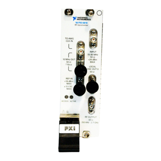
- Page 12 Figure 7. NI 5610 RF Upconverter Module Front Panel Table 1. Device Front Panel Icon Definition Refer to the user documentation for required maintenance measures to ensure user safety and/or preserve the specified EMC performance. 12 | ni.com | NI PXIe-5672 Getting Started Guide...
- Page 13 Routes the IF signal from the NI 5442 AWG module for frequency translation. LOCAL OSC OUT 0 Routes the auxiliary local oscillator signal. RF OUTPUT Routes the upconverted signal at the requested RF frequency. NI PXIe-5672 Getting Started Guide | © National Instruments | 13...
- Page 14 RED—The module has detected an error state; this state may indicate an overload (reverse power protection circuit is open), a PLL lock failure, or a thermal shutdown condition. 14 | ni.com | NI PXIe-5672 Getting Started Guide...
- Page 15 Figure 8. NI 5442 AWG Module Front Panel Table 4. Device Front Panel Icon Definition Refer to the user documentation for required maintenance measures to ensure user safety and/or preserve the specified EMC performance. NI PXIe-5672 Getting Started Guide | © National Instruments | 15...
-
Page 16: Configuring The Ni 5672 In Max
Configuring the NI 5672 in MAX Use Measurement & Automation Explorer (MAX) to configure your National Instruments hardware. MAX informs other programs about which devices reside in the system and how they are configured. MAX is automatically installed with NI-RFSG. - Page 17 The MAX self-test performs a basic verification of hardware resources. Related Information Interconnecting the NI 5672 Modules on page 10 Refer to the NI RF Signal Generators Help for information about renaming devices. NI PXIe-5672 Getting Started Guide | © National Instruments | 17...
-
Page 18: Programming The Ni 5672
ADEs that organizes examples into categories and allows you to easily browse and search installed examples. You can see descriptions and compatible hardware models for each example or see all the examples compatible with one particular hardware model. 18 | ni.com | NI PXIe-5672 Getting Started Guide... -
Page 19: Generating A Signal Using The Ni-Rfsg Soft Front Panel
You can use the Search button on the Functions palette to find the NI- RFSG palette. Add the core NI-RFSG VIs from the NI-RFSG palette to the block diagram, and wire the VIs together as shown in the following figure. NI PXIe-5672 Getting Started Guide | © National Instruments | 19... - Page 20 Structures palette. Enclose the niRFSG Check Generation Status VI in the While Loop, as shown in the following figure. Figure 11. The niRFSG Check Generation Status VI Enclosed in the While Loop 20 | ni.com | NI PXIe-5672 Getting Started Guide...
- Page 21 Create an error indicator by right-clicking the error out output of the niRFSG Close VI and selecting Create»Indicator. Verify that the VI block diagram and VI front panel now look similar to the following figures. NI PXIe-5672 Getting Started Guide | © National Instruments | 21...
- Page 22 Click the Run button on the toolbar to initiate sine wave generation. Click the VI front panel STOP button to stop sine wave generation. You have successfully generated a continuous sine wave signal using the NI-RFSG instrument driver and the NI 5672. 22 | ni.com | NI PXIe-5672 Getting Started Guide...
-
Page 23: Troubleshooting
Right-click the Start screen, and select All apps»Control Panel» Hardware and Sound»Device Manager. Windows 7 Select Start»Control Panel»Device Manager. Windows Vista Select Start»Control Panel»System and Maintenance»Device Manager. Windows XP Select Start»Control Panel»System»Hardware»Device Manager. NI PXIe-5672 Getting Started Guide | © National Instruments | 23... -
Page 24: What Should I Do If The Module Fails The Self-Test
If you are using a PXI controller, verify that a National Instruments entry appears in the system device list. Reinstall NI-RFSG and the device if error conditions appear in the list. If you are using an MXI controller, right-click PCI-to-PCI Bridge, and select Properties from the shortcut menu to verify that the bridge is enabled. -
Page 25: Where To Go Next
RF fundamentals, device features, and programming with NI-RFSG. Worldwide Support and Services The National Instruments website is your complete resource for technical support. At ni.com/ support, you have access to everything from troubleshooting and application development self-help resources to email and phone assistance from NI Application Engineers. - Page 26 Other product and company names mentioned herein are trademarks or trade names of their respective companies. For patents covering National Instruments products/technology, refer to the appropriate location: Help»Patents in your software, the file on your media, or the National Instruments Patent Notice at .
Need help?
Do you have a question about the PXIe-5672 and is the answer not in the manual?
Questions and answers