Table of Contents
Advertisement
Quick Links
Advertisement
Table of Contents

Related Manuals for National Instruments NI 5741


Summary of Contents for National Instruments NI 5741
- Page 1 NI-5741...
-
Page 2: Table Of Contents
NI 5741 16-Channel Signal Generator Before you begin, install and configure your chassis and controller. Note The NI 5741 is a 16-channel, 1 MS/s analog output adapter module designed to work in ™ conjunction with your NI FlexRIO FPGA module. -
Page 3: Electromagnetic Compatibility Guidelines
Furthermore, any modifications to the product not expressly approved by National Instruments could void your authority to operate it under your local regulatory rules. -
Page 4: Flexrio Documentation Locations
CLIP details for module your adapter module. Specifications Available from the Start menu and Contains specifications for document for your at ni.com/manuals. your adapter module. adapter module NI 5741 Getting Started Guide | © National Instruments | 3... -
Page 5: Verifying The System Requirements
Verifying the System Requirements To use the NI 5741, your system must meet certain requirements. For more information about minimum system requirements, recommended system, and supported application development environments (ADEs), refer to the readme, which is available on the software media or online at ni.com/updates. -
Page 6: Preparing The Environment
Unpack any other items and documentation from the kit. Store the device in the antistatic package when the device is not in use. Preparing the Environment Ensure that the environment you are using the NI 5741 in meets the following specifications................Operating temperature 0 °C to 55 °C... -
Page 7: Installing The Ni Flexrio Devices
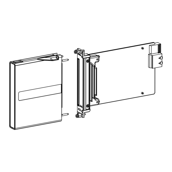
Gently insert the guide pins and the high-density card edge of the NI FlexRIO adapter module into the corresponding connectors of the NI FlexRIO FPGA module, as shown in the figure below. 6 | ni.com | NI 5741 Getting Started Guide... -
Page 8: Connecting Cables
I/O connector. NI recommends using the SCB-19 connector block to access the DIO and PFI signals. • Use the NI SHC68-C68-D4 VHDCI cable (NI part number: 196275-01) to connect to the AO 0-15 connector. NI 5741 Getting Started Guide | © National Instruments | 7... -
Page 9: Removing The Adapter Module
Store the module in the original antistatic packaging when not in use to avoid damage. Installing Accessories The NI SMB-2152 is a breakout box accessory for debugging your NI 5741. The NI part number for the NI SMB-2152 is 189408F-08L. -
Page 10: Appendix A: Ni 5741 Features
Appendix A: NI 5741 Features Front Panel and Connector Pinouts The following figure shows the front panel connector and signal descriptions for the NI 5741. Figure 4. NI 5741 Front Panel Connectors 0-15 PFI 0 1 MS/s 16-Bit Analog Output... - Page 11 Connections that exceed any of the maximum ratings of any connector on Caution the NI 5741 can damage the device and the chassis. NI is not liable for any damage resulting from such connections. Figure 5. NI 5741 Analog Output Connector Pinout...
-
Page 12: Block Diagrams
Caution the AUX I/O port is not an HDMI interface. Do not connect the AUX I/O port on the NI 5741 to the HDMI port of another device. NI is not liable for any damage resulting from such signal connections. -
Page 13: Appendix B: Interfacing With The Ni 5741
LabVIEW project. CLIP and LabVIEW FPGA The interface between the NI 5741 CLIP and LabVIEW FPGA in the following figures. If you are using an NI FlexRIO FPGA module with a Virtex-5 FPGA, refer to the following figure, which shows the relationship between the CLIP and an FPGA VI configured for use with a Virtex-5 FPGA target. - Page 14 If you are using an NI FlexRIO FPGA module with a Kintex-7 FPGA, refer to the following figure, which shows the relationship between the CLIP and an FPGA VI configured for use with a Kintex-7 FPGA target. NI 5741 Getting Started Guide | © National Instruments | 13...
- Page 15 DRAM NI 5741 CLIP The NI 5741 CLIP provides access to sixteen 16-bit analog output channels, eight bidirectional DIO channels, four bidirectional PFI channels, and one bidirectional trigger line. The following figure shows the relationship between the NI 5741 and LabVIEW FPGA.
-
Page 16: Clocking
Clocking The NI 5741 clock source controls the sample rate and other timing functions on the device. The following table contains information about the possible NI 5741 clock sources. Table 3. NI 5741 CLIP Clock Sources Clock Frequency DAC Clock... -
Page 17: Worldwide Support And Services
National Instruments trademarks. Other product and company names mentioned herein are trademarks or trade names of their respective companies. For patents covering National Instruments products/technology, refer to the appropriate location: Help»Patents in your software, the patents.txt ni.com/patents file on your media, or the National Instruments Patent Notice at .
Need help?
Do you have a question about the NI 5741 and is the answer not in the manual?
Questions and answers