
Related Manuals for Moxa Technologies C320


Summary of Contents for Moxa Technologies C320
- Page 1 C320 Turbo/PCI User’s Manual Fourth Edition, July 2008 www.moxa.com/product © 2008 Moxa Inc., all rights reserved. Reproduction without permission is prohibited.
- Page 2 C320 Turbo/PCI User’s Manual The software described in this manual is furnished under a license agreement and may be used only in accordance with the terms of that agreement. Copyright Notice Copyright © 2008 Moxa Inc. All rights reserved. Reproduction without permission is prohibited.
- Page 3 About This Manual This manual is composed of six Chapters and one Appendix. This manual is written for installer, system administrator and software programmer. If you are a first-time installer and system administrator, we recommend you to go through the whole manual except Chapter 4.
-
Page 4: Table Of Contents
Table of Contents Introduction Introduction ....................1-1 Introduction Introduction Overview ........................ 1-1 Features......................... 1-4 Check List ......................1-5 Installation Guide ....................1-6 Hardware Installation................2-1 Hardware Installation Hardware Installation Hardware Installation Installing the Intellio C320Turbo/PCI Control Board ..........2-1 Installing the External Modules ................2-2 Installing the CPU and UART Modules (Desktop)...............2-2 Installing the Basic and Extensive Modules (Rackmount)...........2-5 Operating LED Indicators.................. - Page 5 Serial Programming Tools..............4-1 Serial Programming Tools Serial Programming Tools Serial Programming Tools Windows NT and Windows 95/98 ................4-1 Installation..........................4-1 PComm Programming Library.....................4-2 Utilities ..........................4-2 UNIX ........................4-5 Programming the MOXA Ports....................4-5 Extended UNIX Ioctl() Commands ..................4-5 Utilities ..........................4-11 Connection Option and Cable Wiring Connection Option and Cable Wiring ............
-
Page 6: Introduction
1 1 1 1 1 1 1 1 Introduction This manual covers both the hardware and software installation and configuration of C320Turbo/PCI, which is the member of the Intellio Family. In addition, the professional serial comm tools, PComm under Windows NT and Windows 95/98 and extended UNIX system calls, and utilities are introduced. - Page 7 Low Host Processor Overhead The Intellio C320Turbo/PCI is equipped with two high performance processors (TMS320) on both the Control Board and the CPU/Basic Module and 512KB on- board memory to relieve the host’s CPU workload of all data and I/O handling tasks. The memory buffer holds transmitted and received data to prevent data loss.
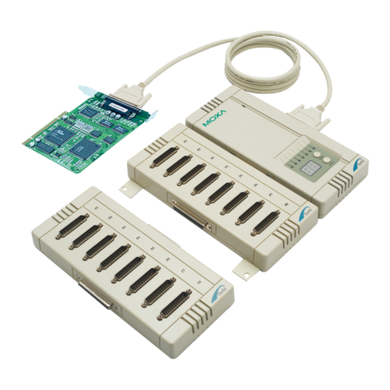
- Page 8 Introduction U A R T U A R T C P U M o d u le M o d u le M o du le E x ten siv e M o du le D B 2 5 to D B 2 5 C a ble C 3 2 0 Turbo/P C I B a sic M o d u le Surge/Isolation Protection...
-
Page 9: Features
Point-of-Sale (POS) System Features The following is a summary of all the outstanding features of Intellio C320 Turbo/PCI: High speed serial communication-Up to 460.8 Kbps Low host CPU's overhead-Dual RISC processor architecture Reliability-On-chip hardware flow control guarantees no data loss Modular expandability-Easy to add ports for a single PC slot... -
Page 10: Check List
Introduction Rack mountable-Industrial standard 19” rack Supports most popular OS-Windows NT, Windows 95/98, UNIX, Linux Friendly user interface for configuration and utilities Powerful but easy serial programming library and illustrative examples Check List Upon unpacking Intellio C320Turbo/PCI package, you should find the following items: One Intellio C320Turbo/PCI Control Board One CPU Module or Basic Module... -
Page 11: Installation Guide
Installation Guide This section gives a brief summary of how to install the Intellio C320Turbo/PCI under each supported operating system. Installation is simple and involves the following stages: Check the PCI BIOS settings Install the Intellio C320Turbo/PCI board See chapter 2 and the connection option (cable/module) Install the software from the diskette See respective O.S. -
Page 12: Hardware Installation
2 2 2 2 2 2 2 2 Hardware Installation Hardware Installation Hardware Installation Hardware Installation The installation of Intellio C320Turbo/PCI consists of hardware installation and software installation. For software installation, please refer to the respective section of operating systems in the next chapter. Hardware installation is stated in this chapter. -
Page 13: Installing The External Modules
Step 6: Replace the system cover. Note ! Each board must occupy one unique IRQ and one unique memory address, which are assigned by PCI BIOS automatically. However, you may select the free IRQ number manually via PC’s BIOS setup for PCI slot, but this method is not available for memory. - Page 14 B: Plug the DB25 male end of the shipped 2-meter 25-signal-pin cable into the connector on the rear panel of the Intellio C320Turbo/PCI Control Board. Refer to the chapter 5 for the cable pinout details. 25-signal-pin Cable C320 Turbo/PCI UART Module UART Module CPU Module C: Plug the other DB25 female end into the CPU Module’s DB25...
- Page 15 (the link cable comes with long range extension kit or the one fabricated according to the pinouts in the chapter 5) into the connector on the rear panel of the Intellio C320Turbo /PCI Control Board. 10-signal-pin Cable C320 Turbo/PCI Power Adapter UART Module CPU Module UART Module C: Plug the other DB25 female end into the CPU Module’s DB25...
- Page 16 Hardware Installation Step 8: Connect the first UART Module to the CPU Module. Connect the second UART Module to the first one if necessary and so on. Metal Plate Screws To Control Board CPU Module UART Module UART Module For better fixation of modules, Fixing Kit is available and see the bottom view of modules below to install.
- Page 17 In most cases, you need not a power adapter. Extensive Module 25-singal-pin Cable C320 Turbo/PCI Basic Module A: Set the Basic Module power switch to the OFF position. This is absolutely necessary when installing or removing the cable, the Basic Module or the Extensive Module(s).
- Page 18 Hardware Installation Power Adapter Extensive Module 10-singal-pin C able C 320 Turbo/PC I Basic Module Plug the other DB25 female end into the Basic Module’s DB25 connector. Warning! Do not use a 25-signal-pin cable to connect the Intellio C320Turbo/PCI Control Board to the Basic Module when using the power adapter as this will cause power crash.
- Page 19 To mount the module(s) on the industrial standard 19” rack, Rack Mount Kit, including two L-type plates and eight screws, should be applied. Multiport C ontroller B A S IC M OD U L E Power TxD RxD DTR DSR RTS CTS DCD Module Channel L-type Plate...
- Page 20 Hardware Installation If the first test passed, the CPU/Basic Module will then display “Ld” waiting for loading firmware from the Intellio C320Turbo/PCI Control Board. After loading the firmware, the CPU Module will scan for the number of UART Modules or the number of ports available.
Need help?
Do you have a question about the C320 and is the answer not in the manual?
Questions and answers