Table of Contents
Advertisement
Advertisement
Table of Contents
Troubleshooting

Related Manuals for Full Spectrum Laser Pro Series


Summary of Contents for Full Spectrum Laser Pro Series
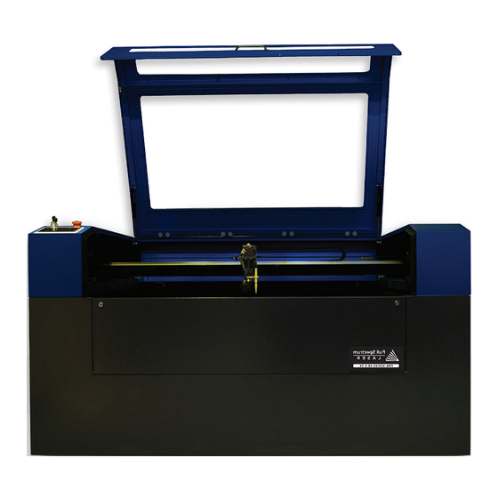
- Page 1 User Manual Pro-Series 36 x 24 & Pro-Series 48x 36...
-
Page 3: Table Of Contents
Table of Contents Section I. Safety First . . . . . . . . . . . . . . . . . . . . . . . . . . . . . . . . . . . . . . . . . . . . 5 General Safety . - Page 4 COMPLIANCE STATEMENT The Full Spectrum Laser Pro-Series Laser System is a class 3R laser product, as defined in International Standard IEC 60825-1. The Full Spectrum Laser Prop-Series Laser System complies with 21 CFR 1040.10 and 1040.11, the Federal Performance Standards for Light-Emitting Products, except for deviations pursuant to Laser Notice No.
-
Page 5: Section I. Safety First
SECTION I. SAFETY FIRST Familiarize yourself with these icons. They indicate areas that require special attention. Pro Tips: Shock Icon: Fragile Icon: Watch for this icon to receive Warns of potential Warns of fragile parts or valuable advice in getting the electrical hazards. -
Page 6: General Safety
General Safety Read and be familiar with all safety protocols and procedures before operating any machinery. It is the responsibility of the operator to ensure all safety precautions are correctly followed and the machine is properly assembled and in working order. ALWAYS inspect the laser cutter for damage or breakage before each use. -
Page 7: Laser Safety
Laser Safety The output of the CO2 engraving laser is fully contained in a Class 1 enclosure during normal operation. The laser cabinet has a safety interlock switch that deactivates the laser if the door is opened during operation. No special precautions are necessary to operate the high power laser safely, however, the output beam of the alignment laser (visible red diode laser) is accessible to the operator during normal operation, giving the total system an overall rating of Class 3R. - Page 8 Class I. It is the operator’s responsibility to ensure that the installation and operation of the Full Spectrum Laser System is performed in accordance with all applicable laws. Copies of ANSI Standard Z136.12000 are available from: LASER INSTITUTE OF AMERICA 12424 RESEARCH PARKWAY, SUITE 125 ORLANDO, FL 32826 (407) 3801553.
-
Page 9: Fire Safety
5lb or larger fire extinguisher on hand. Full Spectrum Laser recommends a Halotron 1 fire extinguisher or a multipurpose dry chemical fire extinguisher. Halotron 1 extinguishers are more expensive than a dry chemical, but offer certain advantages should you ever need to use an extinguisher. - Page 10 Fire Safety (cont .) Woodshop Dust Fire Safety Considerations* Before processing materials the user must verify whether harmful materials can be generated and whether the filter equipment of the exhaust system is suitable for the harmful materials. We emphasize that it is the responsibility of the user, to consider the national and regional threshold values for dust, fogs and gases when selecting the filters and the exhaust system.
-
Page 11: Electrical Safety
Your laser shipped with silicone terminal covers that prevent access to bare wiring—notify Full Spectrum Laser support and immediately cease operations if these covers ever slip and expose bare wire. -
Page 12: Section Ii. Uncrating Your Pro-Series
SECTION II. UNCRATING Pro-Series Toolbox Parts Your laser ships with a toolbox containing parts and accessories: Figure 2.1 Figure 2.2 1. Ignition Keys 2. Door Panel Keys 3. Hex Wrench Set 4. Screw Driver 5. Spare Limit Switch 6. Lens & Mirror Removal Tool 7. -
Page 13: Parts & Accessories
Pro-Series Parts & Accessories Your laser shipped with the following included parts and accessories: Water Tubes Ethernet Cable Exhaust Fan (Toolbox) 6” Exhaust Tube Band 4. 110v Main Machine Honeycomb Cutting Power Cord Clamps (3) (Toolbox) Table Air Compressor Air Compressor Technical Support is available from 8am to 5pm (PST) M - F at support@fslaser.com. -
Page 14: Upgrades & Recommended Accessories
Optional Upgrades & Recommended Accessories 1. Water Chiller 2. Large Fume 3. Medium Fume Extractor Extractor 4. Small Fume 5. 1.5” Focus Lens 6. 2.0” Focus Lens Extractor 7. 2.5” Focus Lens 8. 5” Focus Lens Technical Support is available from 8am to 5pm (PST) M - F at support@fslaser.com. -
Page 15: Uncrating Your Pro-Series
Uncrating Your Pro-Series Laser Cutter When your Pro-Series 48x36 (or 36x24) Laser Cutter arrives, it will require careful uncrating and examination of parts. Follow these instructions for best results. ATTENTION! Be sure to keep the box crate and the packing material used during shipping in case you need to return the machine for warranty service. -
Page 16: Section Iii. Installation & Assembly
SECTION III. INSTALLATION & ASSEMBLY With your laser cutter uncrated and placed in its permanent work space we can now assemble the operating systems. This is a simple process that should take less than an hour to complete. The following stages will be described in detail. Assembly Stages: 1. -
Page 17: Remove Zip Ties
Assembly Stage 1: Remove Zip Ties To secure the machine during shipping, zip ties are used to hold secure the drive belts. These must be removed before operating your laser cutter for the first time. 1. Locate Zip Ties: The motion system is restrained by three (3) zip ties: one on the X-Axis drive belt, and one on each Y-Axis drive. -
Page 18: Connect The Exhaust
Assembly Stage 2: Connect the Exhaust It is mandatory that an exhaust blower is connected and operating whenever you run a job on your laser. A properly installed exhaust blower removes smoke and fumes from the case and exhausts them to the outside of the building. 1. - Page 19 This is a great option for workshops that do not have the option to ventilate outside. Both the extractors and the filters are available on the Full Spectrum Laser website at https://www.fslaser.com/Products/LaserAccessories. For the 36x24 and the 48x36 machines we recommend the Large Fume Extractor: https://www.fslaser.com/Product/LargePurifier.
-
Page 20: Install Laser Tube
Assembly Stage 3: Install Laser Tube Please carefully read all instructions before beginning the laser tube installment procedure as there are several critical steps which must be properly followed. Remember to never operate your laser without properly installed air and water systems running. 1. - Page 21 2. Position the Laser Tube: Take special care how you position the laser tube in the mounts. Incorrect positioning can cause the laser to misfire and damage your machine or create an extreme shock hazard. Facing the back of your machine, the end of the laser tube with the plastic cap should be pointing to your LEFT (away from the optics).
- Page 22 3. Attach the HV Wire. Carefully remove the plastic insulation end-cap (A) and set it aside where you can find it again. Again, when facing the machine from the back, the end cap should be on the LEFT of the properly positioned laser tube. You will be reinserting it into the same position once the red HV wire is connected.
- Page 23 AVOID SHOCK! When powered, the red HV wire conducts 25,000V and must be installed carefully not to arc. Closely inspect the red wire to ensure there are no kinks in the red laser wire and there are no breaks in the insulation. Avoid sharp bends and never put any loops in the red laser wire.
- Page 24 5. Ground the Connector. Carefully attach the black ground wire (found on the RIGHT side of machine, when facing it from the back) with a Phillips screwdriver to the aperture (D) as shown below. Figure 3.12 FRAGILE! Once again, be aware of the fragile glass “pinch-point”...
- Page 25 Figure 3.13 ATTENTION! Full Spectrum Laser is NOT responsible for damages to your machine or laser tube due to improper user installation (see your warranty for full details). If you have any doubt as to the installation process presented in this document, contact our customer service team at support@fslaser.com to confirm your laser...
-
Page 26: Connect The Water Chiller
Assembly Stage 4: Connect the Water Chiller Your laser uses a water-cooled continuous beam CO2 laser tube. The tube requires a flow of room temperature (or cooler) water to regulate the temperature of the resonance chamber. You purchased either the passive water chiller (which cycles water at room temperature) or the active water chiller (which cools the water to a constant temperature). - Page 27 2. Connect Alarm Signal: The alarm signal will alert the user if the water chiller is disconnected, malfunctioning, or requires water. Connect the 3-prog end of the signal cord to the water chiller, and the 4-prog end into your Pro-Series. 3.
-
Page 28: Assemble The Air Compressor
Assembly Stage 5: Assemble the Air Compressor Air is used as a pressurized gas to assist in cutting and engraving operations. This pressurized air is critical to safe and efficient cutting operations as it not only helps cut through material more quickly, but also helps prevent the formation of flames. - Page 29 3. Attach Air Hose to Laser Cutter: Insert other end of the silicone air inlet hose onto the “air inlet” slot in the back of laser cutter. WATER IN AIR IN WATER OUT SIGNAL Figure 3.18 Technical Support is available from 8am to 5pm (PST) M - F at support@fslaser.com.
-
Page 30: Connect Electrical Power
Assembly Stage 6: Connect Electrical Power The Full Spectrum Laser Pro-Series and available accessories are configured to accept 110VAC at 60Hz by default. 220VAC can be specified and these units connect directly to 220V 50/60 Hz. If you are unsure which voltage was specified, contact support@fslaser.com. -
Page 31: Connecting Ethernet Cable
Assembly Stage 7: Connecting Ethernet Cable RetinaEngrave is a combination of a print driver and control software that communicates with, downloads jobs to, and controls the laser system. There is no download required for RetinaEngrave. With a local connection (achievable with Wi-Fi or the included Ethernet cable) your machine will link with the software’s IP address. -
Page 32: Connect To Retinaengrave
Assembly Stage 8: Connect to Software System Requirements: - Windows Vista and higher - Minimum 2GB Ram - Dual Core Processor 1. Go to Download Page: Turn on your computer or laptop, now connected to your laser cutter via the Ethernet cable, or a router. In your favorite browser (Google Chrome is recommended) go to http://fslaser.com/RetinaEngrave. -
Page 33: Section Iv. Tests & Adjustments
SECTION IV. TESTS & ADJUSTMENTS It is important that your laser is tested and adjusted (if needed) for proper use before you start your first job. The following will be on our list of tests and adjustments: Return/Test Fire 1. Alignment Test 2. -
Page 34: Alignment Test
1 . Alignment Test For this machine, the laser tube was carefully aligned in our facilities in Nevada. When you first turn on your machine, the mirror alignment should be perfect. It is possible, however, that sometimes mirrors may come out alignment during shipping. For all other Pro-Series machines, the operator will need to follow the laser tube installation process. - Page 35 5. Test Fire the Laser: Press the Fire Laser Icon Button on the touch panel. ATTENTION! Find and push this icon on your Pro Series touch panel to test fire the laser. 6. Repeat Test Fire in Other Three Corners:...
-
Page 36: Alignment Procedure
2 . Mirror Alignment Procedure The mirror alignment procedure goal is to first align the visible red beam with the invisible CO2 laser beam then use the red beam as the primary indicator for alignment. The idea is that when the laser is not aligned, you will have two black dots from the test fires in the top and bottom positions. - Page 37 STAGE 1: PREP Prepare your tools and workspace. 1. Safety First: Be aware of all safety procedures and precautions before continuing. 2. Power On Laser Cutter: The machine must be powered on to continue this procedure. Turn on the machine by hitting the power switch. Allow the machine time to boot up the touch panel operating system.
- Page 38 STAGE 2: ALIGN LASER OUTPUT TO MIRROR#1 Conceptually, you will be aligning the invisible cutting beam with the visible red beam diode and making sure they hit each mirror precisely. Once again, remember to check your mirror alignment BEFORE starting this procedure as it is likely unnecessary if the laser tube was pre-installed in your Pro Series.
- Page 39 STAGE 3: ALIGN MIRROR #1 TO MIRROR #2 Because the 2nd mirror moves along with the x-gantry alignment must be checked between mirrors #1 and #2. 1. Open Safety Lid: You will need to access the interior of the machine. 2.
- Page 40 7. Reposition the X-Gantry to “Close” Position: Now that we have a burn mark on our thermal paper from a “far” firing of the laser, we want to fire the laser from the closest position. Move the x-gantry to the upper most position in the machine and test fire again. Figure 4.9 8.
- Page 41 STAGE 4: ALIGN MIRROR #2 TO MIRROR #3 The 3rd mirror is mounted on the laser head assembly and slides along the x-gantry rail. 1. Open Safety Lid: You will need to access the interior of the machine. 2. Place Thermal Paper: Take a small piece of thermal paper (approx.
- Page 42 7. Adjust Red Beam: Using your 2.5mm hex wrench, make micro adjustments to the three adjustment screws of the red beam diode, and position the red dot exactly over the burn mark. 8. Reposition the Laser Head to “Close” Position: Now that we have a burn mark on our thermal paper from a “far”...
- Page 43 STAGE 5: FOCUS LENS ALIGNMENT The focal lens is located at the bottom of the laser head assembly. For proper alignment, the laser beam should always be hitting the center of the focal lens, regardless of the position of the cutting head in the machine.
- Page 44 4. Close Safety Lid: Safety measures should make it impossible to fire the laser with the safety lid open. Regardless, never intentionally fire the laser with safety lid open. 5. Test Fire the Laser: Press the Fire Laser Icon button on the touch panel. You will see a burn mark on the thermal paper.
-
Page 45: Focusing
3 . FOCUSING Focusing the Pro-Series laser cutter is quick and easy. Your laser included an acrylic ruler sized for the included 2.5” focal lens. 1. Place Ruler: Place the included acrylic ruler on the top of gold bracket as shown in the diagram. 2. -
Page 46: Section V. User Interface
SECTION V. USER INTERFACES Pro-Series Laser Cutter Touchscreen Interface The LCD touch panel allows you to control the basic functions of your Pro-Series laser cutter without needing to connect to a computer. This is very convenient during alignment and testing procedures. Figure 5.1 Selection Field Mode Field... -
Page 47: Button Functions
Button Functions Panel function buttons are described below. Typically the icons on the top line are active during Fast XY Jog (Mode 0). The icons on the bottom are typically active during Alignment (Mode 2). Figure 5.2 H. RETURN/TEST FIRE E. -
Page 48: Modes
SUPPORT MODE (MODE 7). This mode allows a Full Spectrum Laser technical expert access your interface remotely to troubleshoot and fix problems. You will have to manually approve a remote access. -
Page 49: Jog Buttons
Jog Buttons Four green arrow keys pointing UP (L), DOWN (N), LEFT (K), and RIGHT (M). In Fast or Slow XY (Modes 0 and 1), the buttons move the laser head left/right and front/back. In File Select (Mode 3) the up and down buttons scroll through the loaded jobs. -
Page 50: Section Vi. Software
SECTION VI. SOFTWARE Validating Control Card RetinaEngrave 3D control cards are preinstalled in all Pro-Series Laser models. If you are a new customer, your laser’s control card is shipped with an 80-hour temporary usage authorization. The 80 hours are only counted while the laser is ON. During the temporary usage period you must connect your laser to your PC while it is connected to the internet and validate your card. - Page 51 Connect your computer to the internet and log in to your email account you registered your purchase with (or the email you used to validate your control card). 7. Send Profile to Full Spectrum Laser: Attach the laser profile file to a new email and send to activation@fullspectrumlaser.com.
-
Page 52: Retinaengrave Software
RetinaEngrave Software All Pro-Series systems are compatible with RetinaEngrave software. This software can import design files, adjust settings, and a host of other functions. You will need to download the software using the instructions in Section III: Installation & Assembly. To access the software, turn on your machine and allow the touch panel to boot. -
Page 53: Topline Menus
Top Line Menus (Left Side) File The File menu allows the user to open up files to engrave. RetinaEngrave supports drag and drop of .xps files for vector cutting and standard image file types (.bmp, .jpg, .png, .tiff) for rasterengraving. Other file types must be printed to the Full Spectrum Engineering Driver or saved as .xps documents. -
Page 54: Tabs
Tabs Tabs submenus: Show 3D Engrave Tab Show Control Panel Help The help menu offers options to inform you about the version of RetinaEngrave you are using, an Activation menu (future functionality), and Troubleshooting and Update fields which will open the FSL website in your default browser. -
Page 55: Line Two Menus
Line Two Menus (Left) Open File [CTRL+O] Open compatible file types (.xps, .bmp, .set, .bin). Save Project [CTRL+S] Save your current project and settings as a .set file. Clear Workspace Clear the workspace of the current job. This feature only exists in prior versions of the software. Zoom In [+], Zoom Out (-) 1:1 Zoom The zoom buttons control the workspace view of the Engrave and Cut tabs. - Page 56 Laser Head Position The default job origin is located at the upper left of your design (0,0 in the workspace) and referenced from the current location of the laser head in the work envelope. The Laser Head Positioning button opens a dialog box that allows you to change the default job origin between the center of the job or the upper left (2 radio buttons in top menu division).
-
Page 57: Control Panel
Mode Select Mode This drop down menu allows you to select between several modes: Raster and Vector modes open their respective tabs, “Raster then Vector” mode will first run the job in the raster tab (black pixels) and then run the job in the vector tab. The Simulate Vector modes create a red dot overlay in the workspace that follows the path of your vector lines at some multiple of the currently selected speed (for example,100% speed at 0.5x runs at equivalent of 50% speed). - Page 58 Vector Layers The Vector Layers section controls the layer order, speed, power and number of repeats for each layer. As discussed in the General Usage subsection, vector layers are based on one of 7 colors. The Contained Objects First check box determines the order of cutting within a particular layer. CUSTOMIZING THE INTERFACE The user interface for RetinaEngrave is built around several tabs relating to functionality (Raster Engrave, Vector Cut, etc).
-
Page 59: Section Vii. Operations
SECTION VII. OPERATIONS Engraving Your Hobby Laser System has several advanced functions that make it easy to bring your designs from your computer into the real world. Engraving is the process by which complex designs are etched into a work piece or a work piece is marked using an additive coating such as Thermark™. Engraving can range from a simple surface mark all the way through deep material removal. - Page 60 Rotate Image 90 Degrees Each button press will rotate the image 90 degree clockwise. Mirror Image Vertically Mirrors the current image about a vertical centerline. Mirror Image Horizontally Mirrors the current image about a vertical centerline. Invert Image Reverses the black and white pixels of the image. Useful for engraving on coated materials. Scale Scales the image larger or smaller.
-
Page 61: Raster Properties
Raster Properties (Control Panel) Raster Power This field and slider allow you to set the firing current as a percentage of the maximum as set in the configuration file. Laser tubes have a minimum activation current; setting this value too low (below 10%) could result in the laser not firing as this is under the minimum activation current. - Page 62 DPI SELECTION Full Spectrum Laser recommends default settings of 500x500dpi for most applications; text as small as 4pt can be engraved at 500 dpi with excellent readability. Typically, 1000 dpi is only used special cases. The dpi setting also affects the delivered power density, as higher dpi settings correspond to a higher number of pulses per square inch.
- Page 63 Getting Better Raster Results A laser has two states: on and off. Every black pixel or “laser dot” is the result of the laser turning on and firing at a particular location. This location is controlled by the input image, which can be thought of as a “map”...
-
Page 64: Vector Cut
Full Spectrum Laser carries out unit testing using CorelDraw X7 and recommends that Hobby Laser owners use this program. If you use different design software and run into a problem with the print interface, we recommend printing to the XPS Document Image Writer or saving as a PDF. - Page 65 Rotate Vector 90 Degrees Each button press will rotate the design 90 degree clockwise. Mirror Vector Vertically Mirrors the current vector drawing about a vertical centerline. Mirror Vector Horizontally Mirrors the current design about a horizontal centerline. Resize Vector According To Input Values This button will bring up a dialog box allowing you to change the size of the vector image in the workspace by setting specific X and Y dimensions.
-
Page 66: Vector Import
Vector Current Total power is determined by a combination of delivered current and voltage to the laser tube. The current is directly regulated while voltage is controlled by PWM (Pulse Width Modulation). PWM is a technique whereby an average voltage is delivered in a series of pulses per unit time. In Vector mode you can control both the PWM frequency (power) as well as the delivered current (Vector Current %). -
Page 67: Design Tab
Designating Layers Designating a color to objects/ layers you want to vector cut enables you to take advantage of RetinaEngrave’s ability to specify cutting order, cut speed, laser power and number of repeats for each layer. RetinaEngrave supports up to seven standard color layers for maximum program compatibility: Black, Blue, Red, Magenta, Green, Cyan, and Yellow from the RGB color palette. -
Page 68: Design View
Design View Top Line Buttons (Left Side Open Open a new project. Opening a new project removes any unsaved data in the document design window. Save Save your current project. New Projects Button Opens a new project. Edit Shape Select shapes or points and edit their information (color, thickness, fill, etc). New Line Add a new point to point line. - Page 69 Design View Top Line Buttons (Left Side) Toggle Grid Changes the visibility of the drawing grid in the design area. Toggle Points Changes the grid format from lines to points. Toggle Snap to Grid Enable or disable snap functionality with drawing points. Grid Options This popup menu controls grid display and parameters.
-
Page 70: Drawing & Shop Properties
Render Output drawing to Vector/Raster tabs. Design Selection Menus This dropdown list allows you to select which drawing to make active via a left double click. You can also select the tab of the drawing you would like to work on in the design area. Drawing Properties Drawing Size Set the total work area drawing size units in inches. - Page 71 Stroke Control the stroke thickness (pixels), endpoint shape, joint behavior and miter behavior. Brush Control the color and fill style of the brush. Allows you to create and specify gradients. Fill Brush Specify the properties of a closed shape. Workspace Tools Use the drag handles located on the edges of your design to resize the image.
-
Page 72: Section Viii. Maintenance & Troubleshooting
Belt Installation The belts on your laser system are a consumable item and will eventually stretch beyond a usable length or break. Contact Full Spectrum Laser support to order replacement belts, as needed. REQUIRED TOOLS: 2.5mm hex key (included with accessories) 1. -
Page 73: General Maintenance
General Maintenance Before Every Job: Always be sure your water, air, exhaust, and power systems are properly assembled and operating normally. Be sure that the machine and workspace are clutter-free. Be aware of any material warnings and that you are working in a well-ventilated workspace. Check that your fire extinguisher is up to regulation and is easily accessible. -
Page 74: Troubleshooting
Troubleshooting As with any machinery, individual user results may vary. In this section we will discuss the most common issues users report and the simple solutions to fix them and get back to work. If you cannot find the solution to your problem in this section, please don’t hesitate to contact customer support for personalized discussion of your issue. - Page 75 PROBLEM: Laser head crashes during a job. POSSIBLE CAUSE 1. This issue is only apparent on jobs that take up the full work area or are run close to the edge. SOLUTIONS 1. In either Raster or Vector mode, the laser must first be Homed for the soft limits to work properly. 2.
- Page 76 PROBLEM: PC does not connect to Laser. POSSIBLE CAUSE 1. Internet connection is not properly configured. 2. Third-party anti-virus or firewalls blocking RE from establishing connection. SOLUTIONS 1. Verify that your internet connection is properly configured for DHCP. You must reset the laser after connecting the Ethernet cable.
-
Page 77: Appendixes
Appendix A: Rotary Attachment Installation The rotary attachment requires disconnection of the Y-Axis motor from the motor driver. The attachment effectively replaces the Y-Axis by rotating the object as the laser fires. ROTARY ATTACHMENT INSTALLATION The rotary attachment is a friction-wheel type—objects rest on two driven and two idling wheels and are turned to engrave an image onto the surface of a cylindrical object. - Page 78 Using the Rotary Attachment The rotary attachment is designed to be used within the laser case. Please be aware that any system modifications must be performed by an authorized technician and in accordance with all applicable state and federal laws. ALIGNING YOUR ROTARY ATTACHMENT The best way to align your rotary attachment with the laser head is to build a jig that uses the frame as a reference.
- Page 79 Appendix B: Customer Support Full Spectrum Laser provides the best customer support in the industry. Contact us if you have any questions or issues with your Pro-Series Laser Cutter. We can also offer convenient purchasing of accessory upgrades and replacement of consumable items. Refer to this sheet for all your customer support and reordering needs.
- Page 80 Appendix C: Workflow Checklist 1. Safety First: Ensure workspace is free of fire, electrical and other safety hazards. Be aware of all safety issues when cutting materials with a laser. Always have a fire extinguisher on hand. 2. Power on the laser and all of its components. 3.
- Page 81 You can order new or replacement lenses at http://fslaser.com/Products/LaserAccessories. 2.5” Focus Lens Full Spectrum Laser’s Pro-Series comes standard with a 2.5” lens which is good for cutting up to ¼” of material and engraving detail to around 8pt fonts with a 90w tube. Other lenses are also available that offer different levels of precision, depending on the goals of the project.
- Page 82 Appendix E: Warranty Information Within the first 30 days, Full Spectrum Laser will replace or repair any defective parts free of charge and pay for ground shipping of parts if you paid FSL for shipping. Overnight shipping is available at extra charge.
- Page 83 Looking for a laser cutter that can cut & mark steel? The MC-Series Fiber Cutters by Full Spectrum Laser has the precision and power you are looking for. Rapidly cut many metals with a kerf less than 25um (0.001”): alloy/carbon/stainless steel, copper, aluminum, gold, silver, and titanium.
Need help?
Do you have a question about the Pro Series and is the answer not in the manual?
Questions and answers