Table of Contents
Advertisement
Quick Links
Advertisement
Table of Contents

Related Manuals for Dometic Go Power! Solar All Electric Kit GP-AE-4


Summary of Contents for Dometic Go Power! Solar All Electric Kit GP-AE-4
- Page 1 SCAN FOR THE LATEST MANUAL SOLAR ALL-ELECTRIC KITS User Manual GP-AE-4 GP-AE-6 © 2022 Go Power! Worldwide Technical Support and Product Information gopowersolar.com Go Power! | Dometic 201-710 Redbrick Street Victoria, BC, V8T 5J3 Tel: 1.866.247.6527 76844_MAN_SOLAR-AE_RevH...
-
Page 3: Table Of Contents
CONTENTS 2. GENERAL INFORMATION ............................. 5 2.1 WIRING DIAGRAMS ........................2.2 HOW DOES A GO POWER! SOLAR CHARGING KIT WORK? ............... 2.3 CAUTIONS ............................2.4 KIT PARTS ............................2.4.1 PARTS CHECKLIST ....................... 2.5 REQUIRED TOOLS .......................... 3. PLANNING LOCATIONS ............................11 3.1 SOLAR PANELS .......................... -
Page 5: General Information
2. GENERAL INFORMATION Congratulations on purchasing your Go Power! Solar All Electric Kit. You have chosen a clean, quiet and sustainable power source. Go Power! Solar Kits allow you to power appliances off-gird, without hooking up to shore power or a noisy generator. Go Power! solar kits will keep your batteries charged, ensuring you have power when you need it. - Page 6 GENERAL INFORMATION FIGURE 2-A: SOLAR AE-4 AND AE-6 EXAMPLE WIRING DIAGRAM Legend MC4 Connector Solar Connector (SC) SOLAR AE6 200W 200W 200W 200W 200W 200W SOLAR AE4 Only Solar Extension Cables 10 AWG Cable Entry Plates (CEP) 25' Solar Cables 10 AWG RVC- RVC-...
-
Page 7: Cautions
GENERAL INFORMATION 2.3 CAUTIONS Disconnect all power Electricity can be very dangerous. Installation should be performed only sources before attempting by a licensed electrician or qualified personnel. installation Photovoltaic panels generate DC electricity when exposed to sunlight or other light sources. Contact with the electrically active parts of the panel, such as terminals, can result in burns, sparks and lethal shock whether the panel is connected or disconnected. -
Page 8: Kit Parts
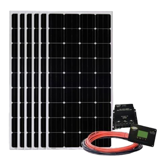
GENERAL INFORMATION 2.4 KIT PARTS CHECKLIST Please unpack and make sure all parts shown in the list below are included in the kit. If any parts are missing please Note contact Go Power!’s customer support team at customersupport@gopowersolar.com or 1-866-247-6527. 2.4.1 PARTS CHECKLIST ITEM # DESCRIPTION... - Page 9 GENERAL INFORMATION UNLESS OTHERWISE SPECIFIED PDM MA DO NOT SCALE DRAWING CHANGES S ELECTRONICAL INTERPRET DIMENSIONS AND TOLERANCES PER ASME Y14.100-2000 TOLERANCES APPLY AS SHOWN BELOW DECIMALS SURF FINISH ANGLES COPY Carmanah Technolo ± .1 ALL RIGHTS RE 6, 7 DOCUMENT MAY B ±...
-
Page 10: Required Tools
GENERAL INFORMATION 2.5 REQUIRED TOOLS a. Screwdriver (with #2 and #3 Phillips bits) h. 2x 7/16” Wrenches b. 1” Hole Saw Caulking Gun Pencil or Marker Sealant d. Pliers k. Digital Multimeter (troubleshooting only) e. Wire Strippers and Cutters Torque Driver (optional) Power Drill g. -
Page 11: Planning Locations
3. PLANNING LOCATIONS 3.1 PLACEMENT OF SOLAR PANELS 1. Remove all solar panels from their boxes. Set aside the boxes as they will be used in the instructions to follow. 2. Using the solar panel boxes as placeholders, plan the layout of the panels on your RV rooftop. Once you have positioned the boxes correctly, leave the boxes on the RV roof as place holders until the panels are installed. -
Page 12: Controller Remote
PLANNING LOCATIONS 3.4 GP-RVC-R CHARGE CONTROLLER REMOTE 1. Plan where the GP-RVC-R remote will be installed. If space will allow, install the GP-RVC-R in the location where you find other instruments and controls (often in the instrumentation panel). Make sure the GP-RVC-R location is also accessible for routing the cable to the GP-RVC-MPPT-30. The GP-RVC-R includes Note 25’... - Page 13 PLANNING LOCATIONS gopowersolar.com | [page 13]...
-
Page 14: Installation
4. INSTALLATION 4. INSTALLATION 4.1 MOUNTING FEET 1. Assemble 4 mounting feet onto each of the solar panels frame using the 1/4” bolts, nuts and washers. This assembly is easily completed on the ground before the panels are brought up to the RV roof (See Figure 4-A). REV ECO # DESCRIPTION DATE... -
Page 15: Cable Entry Plate
INSTALLATION 4.3 CABLE ENTRY PLATE(S) 1. Use the included tie-wraps to secure the cables together ap- proximately every 5’. • This helps reduce the amount of electrical noise Note radiated by the kit. • Ensure these paired cables run through the same FIGURE 4-B hole(s) as they are routed through the interior of the RV. -
Page 16: Charge Controller
SOLAR AE6 INSTALLATION 200W 200W 200W 200W 200W 200W SOLAR AE4 4.5 GP-RVC-MPPT-30 CHARGE CONTROLLER(S) Only You will need the GP-RVC-MPPT-30 User Manual Note included in the kit to complete installation Solar Extension Cables 1. The GP-RVC-MPPT-30 charge controller should be mounted 10 AWG within 9’... -
Page 17: Connections
5. CONNECTIONS 5.1 SOLAR PANELS 1. Before beginning you must securely cover the solar panels with a solid, non-transparent material. We recommend that you use the solar panel shipping boxes. 2. For the SOLAR-AE6 kit, connect 3 strings of 2 solar panels together in series. This means 2 solar panels are to be in series by connecting the positive of one panel to the negative of an adjacent panel. -
Page 18: Battery
CONNECTIONS 5.3 BATTERY WARNING Ensure that correct polarity is being observed when making connections to the batteries. Serious damage to equipment could result if these instructions are not followed exactly. 1. Connect the ring terminal of the negative (black) cable from the GP-RVC-MPPT-30 to the battery’s negative terminal. Connect the ring terminal of the fused positive (red) cable from the GP-RVC-MPPT-30 to the battery’s positive terminal. -
Page 19: Operating Instructions
6. OPERATING 1. The installation is complete. Remove the opaque material from the solar panels. 2. Switch the Circuit Breaker to the on position. 3. Follow the GP-RVC-MPPT-30 User Manual for setup and operating steps. 7. SPECIFICATIONS GP-PV-200M Solar Panel Specs Rated power (Pm) 200W Maximum power voltage (Vmp) -
Page 20: Warranty Return Procedure
8. WARRANTY RETURN PROCEDURE The Go Power! warranty is valid against defects in materials and workmanship for the specific product warranty period. It is not valid against defects resulting from, but not limited to: • Misuse and/or abuse, neglect or accident •... -
Page 21: Cable Entry Drill Template
FIGURE 9-A: CEP DRILL TEMPLATE gopowersolar.com | [page 21]... - Page 22 © 2022 Go Power! Worldwide Technical Support and Product Information gopowersolar.com Go Power! | Dometic 201-710 Redbrick Street Victoria, BC, V8T 5J3 Tel: 1.866.247.6527 76844_MAN_SOLAR-AE_RevH...
Need help?
Do you have a question about the Go Power! Solar All Electric Kit GP-AE-4 and is the answer not in the manual?
Questions and answers