Advertisement
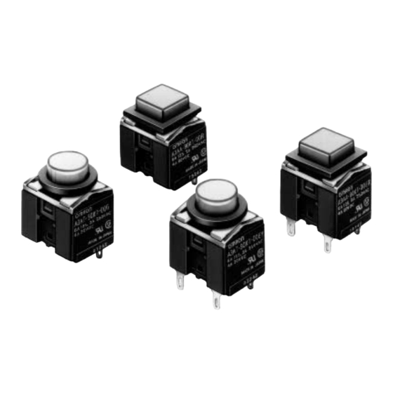
Lighted Pushbutton Switch
Compact Switch Allows Signal and
Power Switching with the Same Model
Compact, high-capacity push-button switch that
has contacts with a 3-mm gap and is ideal as a
power switch.
Capable of switching within the range of 1 mA,
5 VDC to 6 A, 125 VAC.
Requires only 14.5 mm behind the panel.
Options include the following:
•
Round or square
•
Momentary or alternate
•
Surface illumination or non-lighted
UL and CSA approved.
Ordering Information
Model Number Legend
(1) Shape
Symbol
Protection
A
Square
T
Round
(2) Terminal
Symbol
Type
0
Solder
1
PCB
(3) Switch
Symbol
A (See note)
B (See note)
K
L
210
Downloaded from
Elcodis.com
electronic components distributor
(1)
A 3 A A - 9 0 K 1 - 00E R
Operation
Contact type
Momentary
SPDT
3 A at 125 VAC,
2 A at 30 VDC
Alternate
6 A at 125 VAC,
Momentary
SPST-NO
2 A at 250 VAC,
Alternate
4 A at 30 VDC
(2)
(3)
(4)
(4) Illumination
Symbol
Operation
00
Non-lighted
00E
Surface illumination
A3A
(5)
(5) Color
Pushbutton (Non-lighted Models)
Symbol
Color
L
Light gray
R
Red (See note)
Y
Yellow (See note)
G
Green (See note)
A
Blue
B
Black
D
Dark gray
H
Gray
LED (Surface Illumination Models)
Symbol
Color
R
Red
Y
Yellow
G
Green
Note: Common to both lighted and non-
lighted models.
RC
Advertisement
Table of Contents

Subscribe to Our Youtube Channel
Related Manuals for Omron A3AA-90K1-00 Series


Summary of Contents for Omron A3AA-90K1-00 Series
- Page 1 Lighted Pushbutton Switch Compact Switch Allows Signal and Power Switching with the Same Model Compact, high-capacity push-button switch that has contacts with a 3-mm gap and is ideal as a power switch. Capable of switching within the range of 1 mA, 5 VDC to 6 A, 125 VAC.
-
Page 2: List Of Models
List of Models SPST-NO Appearance Terminal Action Illumination Model Color Square (Non-lighted) Solder Momentary Non-lighted A3AA-90K1-00j Surface illumination A3AA-90K1-00Ej A3AA-9jj1-00j A3AA 9jj1 00j R: red R: red A3AA-9jj1-00Ej Alternate Non-lighted A3AA-90L1-00j Y: yellow Y: yellow Surface illumination A3AA-90L1-00Ej G: green G: green Momentary Non-lighted... -
Page 3: Contact Ratings
Accessories (Order Separately) Flange Select according to panel color. Name Shape Classification Model Flange Square, 12.7 x 12.7 Flange alone Black A3A-241 Light gray A3A-242 Round, 12.7 dia. Black A3A-251 Light gray A3A-252 Leaf spring A3A-200 Square, 12.7 x 12.7 Flange and leaf spring Black A3A-211... -
Page 4: Operating Characteristics
Characteristics Operating frequency Mechanical: Momentary action: 120 operations/minute max. Alternate action: 60 operations/minute max. (See note 1.) Electrical: 20 operations/minute max. Insulation resistance 100 MΩ min. (at 500 VDC) Contact resistance 100 mΩ max. (initial value) Dielectric strength 600 VAC, 50/60 Hz for 1 min between terminals of same polarity 2,000 VAC, 50/60 Hz for 1 min between each terminal and ground 600 VAC, 50/60 Hz for 1 min between LED terminals (See note 2.) Vibration resistance... - Page 5 2. An A3A with solder terminals is provided with a black flange and leaf spring for the switching mechanism, however an A3A with PCB terminals is not provided with them. If a black flange and leaf spring are required for an A3A with PCB terminals, order them from your OMRON representative. Downloaded from Elcodis.com...
- Page 6 Dimensions Note: 1. All units are in millimeters unless otherwise indicated. 2. The illustrations below show switches with solder terminals, without a flange or leaf spring. Non-lighted Model Square Pushbutton SPDT SPST-NO Square push-button 8.9 × 8.9 Round Pushbutton Round push-button 15.2 Three, t0.4 terminals...
-
Page 7: Panel Cutouts
Panel Cutouts Square Pushbutton Panel Mounting Dimensions +0.2 11.5 Flange Panel (See note.) +0.2 11.5 Leaf spring 14.5 max. Round Pushbutton Note: 1. Recommended panel +0.2 11.5 dia. thickness: 1 to 1.6 mm 2. The diagram shows the lighted SPST-NO model. For Side-by-side Mounting Mounting Square pushbutton... - Page 8 Terminals Solder terminal PCB terminal SPST- Non-lighted Models Switch terminal: Non-lighted Models Lighted Models t0.4 Switch terminal: t0.4 Lighted Models Lamp terminal: t0.3 Switch terminal: t0.4 Switch terminal: t0.4 Lamp terminal: t0.3 Terminal Arrangement PCB Dimensions (Bottom View) (Bottom View) Holes for models with illuminating Terminal for models...
- Page 9 Installation Mounting and Replacing the Pushbutton Note: Be sure to fit the leaf spring exactly into the groove, and do not allow it to slip out of the groove. Mounting Direction for the Pushbutton and Switch Mount Flange on Panel •...
- Page 10 Precautions Operation LED Characteristics (V – I Characteristics) Ta: Ambient Temperature When operating an A3A, make sure that the A3A has a pushbutton. Do not operate the A3A with a screwdriver or tweezers without mounting a pushbutton to the A3A, otherwise the A3A may malfunc- Ta = 25°C tion.
Need help?
Do you have a question about the A3AA-90K1-00 Series and is the answer not in the manual?
Questions and answers