Table of Contents
Advertisement
Quick Links
Advertisement
Table of Contents

Related Manuals for Supermicro X12STH-F/LN4F


Summary of Contents for Supermicro X12STH-F/LN4F
- Page 1 X12STH-F/LN4F USER'S MANUAL Revision 1.0a...
- Page 2 State of California, USA. The State of California, County of Santa Clara shall be the exclusive venue for the resolution of any such disputes. Supermicro's total liability for all claims will not exceed the price paid for the hardware product.
- Page 3 Pentium processor in an H5 LGA1200 socket. Built with the Intel PCH C256 chipset, the X12STH-F/LN4F supports 128GB DDR4 ECC UDIMM memory with speeds of up to 3200MHz, SATA 3.0 ports, M.2, 1G Base-T ports, and a Trusted Platform Module (TPM) header. Please note that this motherboard is intended to be installed and serviced by professional technicians only.
- Page 4 Super X12STH-F/LN4F User's Manual Contacting Supermicro Headquarters Address: Super Micro Computer, Inc. 980 Rock Ave. San Jose, CA 95131 U.S.A. Tel: +1 (408) 503-8000 Fax: +1 (408) 503-8008 Email: marketing@supermicro.com (General Information) support@supermicro.com (Technical Support) Website: www.supermicro.com Europe Address: Super Micro Computer B.V.
-
Page 5: Table Of Contents
Preface Table of Contents Chapter 1 Introduction 1.1 Checklist ..........................8 Quick Reference .......................12 Quick Reference Table ......................13 Motherboard Features .......................15 1.2 Processor and Chipset Overview ..................18 1.3 Special Features ........................18 Recovery from AC Power Loss ..................18 1.4 System Health Monitoring ....................19 Onboard Voltage Monitors ....................19 Environmental Temperature Control .................19 System Resource Alert......................19... - Page 6 Super X12STH-F/LN4F User's Manual DIMM Removal .........................31 2.5 Rear I/O Ports ........................32 2.6 Front Control Panel ......................37 2.7 Connectors .........................42 Power Connections ......................42 Headers ..........................44 2.8 Jumper Settings .........................51 How Jumpers Work ......................51 2.9 LED Indicators ........................54 Chapter 3 Troubleshooting 3.1 Troubleshooting Procedures ....................56...
- Page 7 Preface 4.8 Save & Exit ........................106 Appendix A BIOS Codes Appendix B Software Appendix C Standardized Warning Statements Appendix D UEFI BIOS Recovery...
-
Page 8: Chapter 1 Introduction
Introduction Congratulations on purchasing your computer motherboard from an industry leader. Supermicro motherboards are designed to provide you with the highest standards in quality and performance. In additon to the motherboard, several important parts that are included in the retail box are listed below. - Page 9 Chapter 1: Introduction Figure 1-1. X12STH-F Motherboard Image Note: All graphics shown in this manual were based upon the latest PCB revision available at the time of publication of the manual. The motherboard you received may or may not look exactly the same as the graphics shown in this manual.
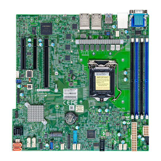
- Page 10 Super X12STH-F/LN4F User's Manual Figure 1-2. X12STH-LN4F Motherboard Image Note: All graphics shown in this manual were based upon the latest PCB revision available at the time of publication of the manual. The motherboard you received may or may not look exactly the same as the graphics shown in this manual.
- Page 11 Chapter 1: Introduction Figure 1-3. X12STH-F Motherboard Layout (not drawn to scale) USB6/7 (3.0) JLD1 COM1 USB0/1 LAN3/4 LAN1/2 BMC_LAN LEDM1 FAN4 JLD2 JIPMB1 22110 X12STH-F IPMI CODE USB2/3 REV:1.01 MAC CODE DESIGNED IN USA 2280 BAR CODE USB4/5 MH12 MEGERAC Intel LICENSE...
-
Page 12: Quick Reference
Super X12STH-F/LN4F User's Manual Quick Reference JLD2 USB0/1 LEDM1 LAN3/4 SLOT4 JLD1 BMC_LAN LAN1/2 COM1 SLOT5 USB6/7 (3.0) LED1 SLOT6 JUIDB1 USB6/7 (3.0) COM1 JLD1 USB0/1 LAN3/4 LAN1/2 BMC_LAN LEDM1 FAN4 FAN4 DIMMA1 DIMMA2 JLD2 DIMMB1 DIMMB2 JIPMB1 JIPMB1 JWD1... -
Page 13: Quick Reference Table
Chapter 1: Introduction Quick Reference Table Jumper Description Default Setting JBT1 CMOS Clear Open (Normal) JPG1 VGA Enable/Disable Pins 1-2 (Enabled) JPME2 ME Manufacturing Mode Pins 1-2 (Normal) JWD1 Watch Dog Timer Pins 1-2 (Reset) Description Status LED1 Unit Identifier (UID) LED Solid Blue: Unit Identified LED3 PCIe M.2 Activity LED... - Page 14 Super X12STH-F/LN4F User's Manual Connector Description M.2-P M.2 PCIe 3.0 x4 Slot (Supports M-Key 2280 and 22110) M.2 NVME MH1-7, MH12 Mounting Holes SLOT4 PCH PCIe 3.0 x4 (IN x8) Slot SLOT5 CPU PCIe 4.0 x4 (IN x8) Slot (SLOT5 will be disabled when a Pentium processor is installed) SLOT6 CPU PCIe 4.0 x16 Slot (SLOT6 will run at PCIe 3.0 x16 when a Pentium processor is installed)
-
Page 15: Motherboard Features
Note: Speed support is up to 2666MHz when a Pentium processor is installed. Speed support is up to 2933MHz for 2R2R configurations. DIMM Size • 8GB, 16GB, 32GB at 1.2V Note: For the latest CPU/memory updates, please refer to our website at http://www.supermicro.com/products/ motherboard. Chipset • Intel C256 Expansion Slots •... - Page 16 Super X12STH-F/LN4F User's Manual Motherboard Features Peripheral Devices • Two USB 2.0 ports on the rear I/O panel (USB0/1) • Two front accessible USB 2.0 headers with two USB connections (USB2/3, USB4/5) • Two USB 3.2 Gen 1x1 ports on the rear I/O panel (USB6/7) •...
- Page 17 DDR4 (2DPC) LGA1200 ECC UDIMM SMBUS PCIE Gen3 (Gen4 on RKL-E) x4 PEG60[0:3] SLOT5 x8 connector X12STH-F/LN4F Only DMI Gen3 x8 USB2.0 Back Panel P5 P7 JUSBRJ45 RMII / NCSI RGMII PCIE Gen3 x1 P[5] PCIE Gen3 x4 P[1:4]...
-
Page 18: Processor And Chipset Overview
X12STH-F/LN4F motherboard provides system performance, power efficiency, and feature sets to address the needs of next-generation computer users. The X12STH-F/LN4F dramatically increases system performance for a multitude of server applications. The Intel Xeon E-2300, 10th Generation Pentium processor and the C256 chipset support the following features: •... -
Page 19: System Health Monitoring
Plug and Play, and an operating system-independent interface for configuration control. ACPI leverages the Plug and Play BIOS data structures, while providing a processor architecture-independent implementation that is compatible with appropriate Windows operating systems. For detailed information regarding OS support, please refer to the Supermicro website. -
Page 20: Power Supply
It is recommended that you also install a power surge protector to help avoid problems caused by power surges. 1.7 Serial Port The X12STH-F/LN4F motherboard has one serial port port on the I/O back panel and one header. -
Page 21: Chapter 2 Installation
Chapter 2: Installation Chapter 2 Installation 2.1 Static-Sensitive Devices Electrostatic Discharge (ESD) can damage electronic com ponents. To avoid damaging your system board, it is important to handle it very carefully. The following measures are generally sufficient to protect your equipment from ESD. Precautions •... -
Page 22: Processor And Heatsink Installation
Thermal grease is pre-applied on a new heatsink. No additional thermal grease is needed. • Refer to the Supermicro website for updates on processor support. • All graphics in this manual are for illustrations only. Your components may look different. - Page 23 Chapter 2: Installation 2. Gently lift the load lever to open the load plate. Remove the plastic protective cover. Do not touch the CPU socket contacts. 3. Locate the triangle on the CPU and CPU socket, which indicates the location of Pin 1. Holding the CPU by the edges with your thumb and index finger, align the triangle on the CPU with the triangle on the socket.
-
Page 24: Installing An Active Cpu Heatsink With Fan
Super X12STH-F/LN4F User's Manual 5. Close the load plate, then gently push down the load lever into its locking position. CPU properly installed Load lever locked into place Note: You can only install the CPU in one direction. Make sure it is properly inserted into the socket before closing the load plate. - Page 25 Chapter 2: Installation 6. Align the four heatsink fasteners with the mounting holes on the motherboard. Gently push down the fasteners in a diagonal order (Example: #1 and #2, then #3 and #4) into the mounting holes until you hear a click, then lock the fasteners by turning each one 90°...
-
Page 26: Removing The Heatsink
Super X12STH-F/LN4F User's Manual Removing the Heatsink Note: We do not recommend that the CPU or heatsink be removed. However, if you do need to remove the heatsink, please follow the instructions below to remove the heatsink and prevent damage done to the CPU or other components. -
Page 27: Motherboard Installation
Chapter 2: Installation 2.3 Motherboard Installation All motherboards have standard mounting holes to fit different types of chassis. Make sure that the locations of all the mounting holes for both the motherboard and the chassis match. Although a chassis may have both plastic and metal mounting fasteners, metal ones are highly recommended because they ground the motherboard to the chassis. -
Page 28: Installing The Motherboard
Super X12STH-F/LN4F User's Manual Installing the Motherboard 1. Install the I/O shield into the back of the chassis, if applicable. 2. Locate the mounting holes on the motherboard. See the previous page for the location. 3. Locate the matching mounting holes on the chassis. Align the mounting holes on the motherboard against the mounting holes on the chassis. -
Page 29: Memory Support And Installation
Memory Support The X12STH-F/LN4F supports up to 128GB of DDR4 ECC UDIMM memory with speeds of up to 3200MHz in four memory slots. Speed support is up to 2666MHz when a Pentium processor is installed. Speed support is up to 2933MHz for 2R2R configurations. Refer to the table below for the recommended DIMM population order. -
Page 30: General Guidelines For Optimizing Memory Performance
Super X12STH-F/LN4F User's Manual General Guidelines for Optimizing Memory Performance • The blue slots must be populated first. • It's recommended to use DDR4 memory of the same type, size, and speed. • Mixed DIMM speeds can be installed. However, all DIMMs will run at the speed of the slowest DIMM. -
Page 31: Dimm Installation
Chapter 2: Installation DIMM Installation 1. Insert DIMM modules in the following USB6/7 (3.0) JLD1 COM1 USB0/1 LAN3/4 LAN1/2 order: DIMMB2, DIMMA2, then DIMMB1, BMC_LAN LEDM1 FAN4 DIMMA1. For the system to work properly, use memory modules of the same type JLD2 and speed. -
Page 32: Rear I/O Ports
Super X12STH-F/LN4F User's Manual 2.5 Rear I/O Ports See Figure 2-1 below for the locations and descriptions of the various I/O ports on the rear of the motherboard. USB6/7 (3.0) COM1 JLD1 USB0/1 LAN3/4 LAN1/2 BMC_LAN LEDM1 FAN4 JLD2 JIPMB1... - Page 33 Chapter 2: Installation LAN Ports The X12STH-F has two gigabit Ethernet ports (LAN1, LAN2) on the back I/O panel, while the X12STH-LN4F has four (LAN1 ~ LAN4). In addition to the LAN ports, a dedicated BMC LAN port is located above USB0/1. Please refer to the LED Indicator section for LAN LED information.
- Page 34 Super X12STH-F/LN4F User's Manual Universal Serial Bus (USB) Ports There are two USB 2.0 ports (USB0/1) on the I/O back panel and two USB 2.0 headers (USB2/3 and USB4/5) on the motherboard. The motherboard also has two USB 3.2 ports (USB6/7) on the I/O back panel and one front access USB 3.2 header (USB9/10).
- Page 35 Chapter 2: Installation COM Port There is one COM port on the I/O back panel and one COM header on the motherboard. Refer to the board layout below for the locations. COM Port (COM1) Pin Definitions Pin# Definition Pin# Definition Ground VGA Port A video (VGA) port is located on the I/O back panel.
- Page 36 Super X12STH-F/LN4F User's Manual Unit Identifier Switch (UID-SW): One button with two functions A Unit Identifier (UID) switch and two LED Indicators are located on the motherboard. The UID switch is located JUIDB1. The UID LED (LED1) is located next to the UID switch. When you press the switch, the LED will be turned on, which provides easy identification of a system unit that may be in need of service.
-
Page 37: Front Control Panel
JF1 contains header pins for various buttons and indicators that are normally located on a control panel at the front of the chassis. These connectors are designed specifically for use with Supermicro chassis. See the figure below for the descriptions of the front control panel buttons and LED indicators. - Page 38 Super X12STH-F/LN4F User's Manual Power Button The Power Button connection is located on pins 1 and 2 of JF1. Momentarily contacting both pins will power on/off the system. This button can also be configured to function as a suspend button (with a setting in the BIOS - see Chapter 4). To turn off the power when the system is in suspend mode, press the button for 4 seconds or longer.
- Page 39 Chapter 2: Installation Power Fail LED The Power Fail LED connection is located on pins 5 and 6 of JF1. Refer to the table below for pin definitions. Power Fail LED Pin Definitions (JF1) Pin# Definition 3.3V PWR Supply Fail Overheat (OH)/Fan Fail Connect an LED cable to pins 7 and 8 of the Front Control Panel to use the Overheat/Fan Fail LED connections.
- Page 40 Super X12STH-F/LN4F User's Manual NIC1/NIC2 (LAN1/LAN2) The NIC (Network Interface Controller) LED connection for LAN port 1 is located on pins 11 and 12 of JF1, and LAN port 2 is on pins 9 and 10. Attach the NIC LED cables here to display network activity.
- Page 41 Chapter 2: Installation Power LED The Power LED connection is located on pins 15 and 16 of JF1. Refer to the table below for pin definitions. Power LED Pin Definitions (JF1) Pins Definition 3.3V PWR LED NMI Button The non-maskable interrupt (NMI) button header is located on pins 19 and 20 of JF1. Refer to the table below for pin definitions.
-
Page 42: Connectors
Super X12STH-F/LN4F User's Manual 2.7 Connectors Power Connections ATX Power Supply Connector The 24-pin power supply connector (JPWR1) meets the ATX SSI EPS 24-pin specification. You must also connect the 8-pin (JPWR2) CPU power connector to the power supply. ATX Power 24-pin Connector... - Page 43 Chapter 2: Installation 8-Pin CPU Power Connector JPWR2 is an 8-pin 12V DC power input for the CPU that must be connected to the power supply. Refer to the table below for pin definitions. 8-pin Power Pin Definitions Pin# Definition 1 - 4 Ground 5 - 8...
-
Page 44: Headers
Super X12STH-F/LN4F User's Manual Headers Fan Headers There are six 4-pin fan headers (FAN1 - FAN4, FANA, FANB) on the motherboard. All these 4-pin fan headers are backwards compatible with the traditional 3-pin fans. However, fan speed control is available for 4-pin fans only by Thermal Management via the Hardware Monitoring through BMC. - Page 45 Port 80 connection. Use this header to enhance system performance and data security. Refer to the table below for pin definitions. Please go to the following link for more information on the TPM: http://www.supermicro.com/manuals/other/TPM.pdf. Trusted Platform Module/Port80 Header Pin Definitions...
- Page 46 Super X12STH-F/LN4F User's Manual Standby Power The Standby Power header is located at JSTBY1 on the motherboard. You must have a card with a Standby Power connector and a cable to use this feature. Refer to the table below for pin definitions.
- Page 47 Chapter 2: Installation 4-pin BMC External I C Header A system Management Bus header for IPMI 2.0 is located at JIPMB1. Connect the approriate cable here to use the IPMB I C connection on your system. Refer to the table below for pin definitions.
- Page 48 Super X12STH-F/LN4F User's Manual Power SMB (I²C) Header The Power System Management Bus (I²C) connector JPI²C1 monitors the power supply, fan, and system temperatures. Refer to the table below for pin definitions. Power SMB Header Pin Definitions Pin# Definition Clock...
- Page 49 Chapter 2: Installation SATA 3.0 Ports/Mini-SAS The X12STH-F/LN4F has eight SATA 3.0 ports JSATA (I-SATA0-3) and I-SATA4-7 supported by the Intel C256 chipset. These Intel PCH SATA 3.0 ports offer RAID 0, 1, 5, 10. I-SATA0-3 to JSATA Mini-SAS HD (with PCH RAID), I-SATA4-5 to SATA DOM (with PCH RAID), and I-SATA6-7 to SATA (no RAID).
- Page 50 Super X12STH-F/LN4F User's Manual M.2 Slot This motherboard has one M.2 slot. M.2 was formerly known as Next Generation Form Factor (NGFF) and serves to replace mini PCIe. M.2 allows for a variety of card sizes, increased functionality, and spatial efficiency. The M.2 slot on the motherboard supports PCIe 3.0 x4 SSD cards in the 2280 and 22110 form factors.
-
Page 51: Jumper Settings
Chapter 2: Installation 2.8 Jumper Settings How Jumpers Work To modify the operation of the motherboard, jumpers can be used to choose between optional settings. Jumpers create shorts between two pins to change the function of the connector. Pin 1 is identified with a square solder pad on the printed circuit board. See the diagram below for an example of jumping pins 1 and 2. - Page 52 Super X12STH-F/LN4F User's Manual Watch Dog Timer Watch Dog (JWD1) is a system monitor that can reboot the system when a software application hangs. Close pins 1-2 to reset the system if an application hangs. Close pins 2-3 to generate a non-maskable interrupt (NMI) signal for the application that hangs. Refer to the table below for jumper settings.
- Page 53 Chapter 2: Installation ME Manufacturing Mode Close pins 2-3 of jumper JPME2 to bypass SPI flash security and force the system to operate in the manufacturing mode, which allows you to flash the system firmware from a host server for system setting modifications. Refer to the table below for jumper settings. The default setting is Normal.
-
Page 54: Led Indicators
Super X12STH-F/LN4F User's Manual 2.9 LED Indicators BMC Heartbeat LED LEDM1 is the BMC Heartbeat LED. When the LED is blinking green, BMC is working. Refer to the table below for the LED status. BMC Heartbeat LED LED Color Definition... - Page 55 Chapter 2: Installation PCIe M.2 Activity LED LED3 is the M.2 activity LED on the motherboard. When this LED is blinking, there is M.2 activity. Refer to the table below for more information. PCIe M.2 Activity LED LED Color Definition Blinking Green M.2 Active LAN LEDs...
-
Page 56: Chapter 3 Troubleshooting
Super X12STH-F/LN4F User's Manual Chapter 3 Troubleshooting 3.1 Troubleshooting Procedures Use the following procedures to troubleshoot your system. If you have followed all of the procedures below and still need assistance, refer to the ‘Technical Support Procedures’ and/ or ‘Returning Merchandise for Service’ section(s) in this chapter. Always disconnect the AC power cord before adding, changing or installing any non hot-swap hardware components. -
Page 57: No Video
Chapter 3: Troubleshooting No Video 1. If the power is on, but you have no video, remove all add-on cards and cables. 2. Use the speaker to determine if any beep codes are present. Refer to Appendix A for details on beep codes. 3. -
Page 58: Losing The System's Setup Configuration
Super X12STH-F/LN4F User's Manual 3. Make sure that you are using the correct type of ECC DDR4 modules recommended by the manufacturer. 4. Check for bad DIMM modules or slots by swapping a single module among all memory slots and check the results. - Page 59 Chapter 3: Troubleshooting B. If the system becomes unstable before or during OS installation, check the following: 1. Source of installation: Make sure that the devices used for installation are working properly, including boot devices such as CD/DVD. 2. Cable connection: Check to make sure that all cables are connected and working properly.
-
Page 60: Technical Support Procedures
Before contacting Technical Support, please take the following steps. Also, please note that as a motherboard manufacturer, Supermicro also sells motherboards through its channels, so it is best to first check with your distributor or reseller for troubleshooting services. They should know of any possible problems with the specific system configuration that was sold to you. -
Page 61: Frequently Asked Questions
Note: The SPI BIOS chip used on this motherboard cannot be removed. Send your motherboard back to our RMA Department at Supermicro for repair. For BIOS Recovery instructions, please refer to the AMI BIOS Recovery Instructions posted at http://www. -
Page 62: Battery Removal And Installation
Super X12STH-F/LN4F User's Manual 3.4 Battery Removal and Installation Battery Removal To remove the onboard battery, follow the steps below: 1. Power off your system and unplug your power cable. 2. Locate the onboard battery as shown below. 3. Using a tool such as a pen or a small screwdriver, push the battery lock outwards to unlock it. -
Page 63: Returning Merchandise For Service
For faster service, you can also request a RMA authorization online (http://www.supermicro. com/RmaForm/). This warranty only covers normal consumer use and does not cover damages incurred in shipping or from failure due to the alternation, misuse, abuse or improper maintenance of products. -
Page 64: Chapter 4 Uefi Bios
Super X12STH-F/LN4F User's Manual Chapter 4 UEFI BIOS 4.1 Introduction This chapter describes the AMIBIOS™ Setup utility for the motherboard. The BIOS is stored on a chip and can be easily upgraded using a flash program. Note: Due to periodic changes to the BIOS, some settings may have been added or deleted and might not yet be recorded in this manual. -
Page 65: Main Setup
Note: The time is in the 24-hour format. For example, 5:30 P.M. appears as 17:30:00. The date's default value is the BIOS build date after RTC reset. Supermicro X12STH-LN4F BIOS Version This feature displays the version of the BIOS ROM used in the system. - Page 66 Super X12STH-F/LN4F User's Manual Memory Information Total Memory This feature displays the total size of memory available in the system.
-
Page 67: Advanced
Chapter 4: BIOS 4.3 Advanced Use this menu to configure the Advanced settings. Warning: Take caution when changing the Advanced settings. An incorrect value, a very high DRAM frequency, or an incorrect DRAM timing setting may make the system unstable. When this occurs, revert to default manufacturer settings. - Page 68 Super X12STH-F/LN4F User's Manual Bootup NumLock State Use this feature to set the Power-on state for the <Numlock> key. The options are On and Off. Wait For "F1" If Error Use this feature to force the system to wait until the "F1" key is pressed if an error occurs.
- Page 69 Chapter 4: BIOS CPU Configuration The following CPU information will display: • CPU Signature • Microcode Patch • CPU Speed • L1 Data Cache • L1 Instruction Cache • L2 Cache • L3 Cache • • SMX/TXT CPU Flex Ratio Override Use this feature to enable or disable CPU Flex Ratio Prgoramming.
- Page 70 Super X12STH-F/LN4F User's Manual PECI Use this feature to enable or disable Platform Environment Control Interface (PECI). The options are Disabled and Enabled. Use this feature to enable or disable AVX 2/3 instructions. This application is for Big Core only. The options are Enabled and Disabled.
- Page 71 Chapter 4: BIOS Intel ® SpeedStep™ Intel SpeedStep Technology allows the system to automatically adjust processor voltage and core frequency to reduce power consumption and heat dissipation. The options are Disabled and Enabled. Race to Halt (RTH) Use this feature to enable Race to Halt, which dynamically increases CPU frequency in order to enter the package C-State faster.
- Page 72 Super X12STH-F/LN4F User's Manual Power Limit 4 Override Select Enabled to support average power limit (PL4) override. The options are Disabled and Enabled. C-States Use this feature to enable the C-State of the CPU. The options are Disabled and Enabled.
- Page 73 Chapter 4: BIOS SGX settings Software Guard Extensions (SGX) Use this feature to enable or disable software guard extensions. The options are Disabled, Enabled, and Software Controlled. If the feature above is set to Software Controlled, the next four features are available for configuration: Select Owner EPOCH input type Use this feature to select the EPOCH mode.
- Page 74 Super X12STH-F/LN4F User's Manual • Memory Timing (tCL-tRCD-tRP-tRAS) • DIMMA1 • DIMMA2 • DIMMB1 • DIMMB2 DDR Speed Control Use this feature to set the DDR speed. The options are Auto and Manual. If the feature above is set to Manual, Maximum Memory Frequency and SA GV High...
- Page 75 Chapter 4: BIOS Pwr Down Idle Timer Use this feature to set the power down idle timer. The default value is 0. Memory Scrambler Use this feature to enable or disable memory scrambler support. The options are Disabled and Enabled. Force ColdReset Use this feature to enable or disable a cold boot during a MRC execution.
- Page 76 Super X12STH-F/LN4F User's Manual PEG Configuration CPU SLOT6 PCI-E 4.0 X16 CPU SLOT6 PCI-E 4.0 X16 Use this feature to enable or disable the PCI Express Graphics (PEG) device in the specified port. The options are Disabled and Enabled.
- Page 77 Chapter 4: BIOS PCIe Speed Use this feature to select PCIe support for the device installed. The options are Auto, Gen1, Gen2, Gen3, and Gen4. CPU SLOT5 PCI-E 4.0 X4 (IN X8) CPU SLOT5 PCI-E 4.0 X4 (IN X8) Use this feature to enable or disable the PCI Express Graphics (PEG) device in the specified port.
- Page 78 Super X12STH-F/LN4F User's Manual IGD VTD Enable Use this feature to enable or disable IGD VTD. The options are Enabled and Disabled. IOP VTD Enable Use this feature to enable or disable IOP VTD. The options are Enabled and Disabled.
- Page 79 Chapter 4: BIOS Port 61h Bit-4 Emulation Select Enabled to enable the emulation of Port 61h bit-4 toggling in System Management Mode (SMM). The options are Disabled and Enabled. PCIe PLL SSC Use this feature to enable or disable PCIe PLL SSC. The options are Enabled and Disabled. Super IO Configuration ...
- Page 80 Super X12STH-F/LN4F User's Manual Serial Port 2 Attribute Use this feature to select the serial port 2 mode. The options are SOL and COM. Serial Port Console Configuration COM1 Console Redirection Select Enabled to enable console redirection support for the serial port. The options are Disabled and Enabled.
- Page 81 Chapter 4: BIOS Flow Control Use this feature to set the flow control for Console Redirection to prevent data loss caused by buffer overflow. Send a "Stop" signal to stop sending data when the receiving buffer is full. Send a "Start" signal to start sending data when the receiving buffer is empty. The options are None and Hardware RTS/CTS.
- Page 82 Super X12STH-F/LN4F User's Manual Bits per second Use this feature to set the transmission speed for a serial port used in Console Redirection. Make sure that the same speed is used in the host computer and the client computer. A lower transmission speed may be required for long and busy lines.
- Page 83 Chapter 4: BIOS Legacy Console Redirection Settings Redirection COM Port Use this feature to select the COM port to display redirection of Legacy OS OPROM messages. The options are COM1 and SOL/COM2. Legacy OS Redirection Resolution Use this feature to select the number of rows and columns used in Console Redirection for legacy OS support.
- Page 84 Super X12STH-F/LN4F User's Manual Flow Control EMS Use this item to set the flow control for Console Redirection to prevent data loss caused by buffer overflow. Send a "Stop" signal to stop sending data when the receiving buffer is full. Send a "Start" signal to start sending data when the receiving buffer is empty. The options are None, Hardware RTS/CTS, and Software Xon/Xoff.
- Page 85 Chapter 4: BIOS SATA Port 0-7 SATA Device Type Use this feature to specify if the SATA port specified should be connected to a Solid State Drive or a Hard Disk Drive. The options are Hard Disk Drive and Solid State Drive. PCH-FW Configuration The following firmware information will display: •...
- Page 86 Super X12STH-F/LN4F User's Manual USB Configuration USB Configuration USB Module Version: USB Controllers: USB Devices: Legacy USB Support Select Enabled to support onboard legacy USB devices. Select Auto to disable legacy support if there are no legacy USB devices present. Select Disable to have all USB devices available for EFI applications only.
- Page 87 Chapter 4: BIOS PCIe/PCI/PnP Configuration Onboard Video Option ROM Use this feature to select which firmware function to be loaded for LAN1 used for system boot. The options are Disabled and Legacy (if the Boot Mode Select feature under the Boot tab is set to Legacy), Disabled and EFI (if the Boot Mode Select feature under the Boot tab is set to UEFI), and Disabled, Legacy, and EFI (if the Boot Mode Select feature under the Boot tab is set to Dual).
- Page 88 Super X12STH-F/LN4F User's Manual CPU SLOT6 PCI-E 4.0 X16 OPROM Use this feature to select which firmware type to be loaded for the add-on card in this slot. The options are Disabled and Legacy (if the Boot Mode Select feature under the Boot tab...
- Page 89 Chapter 4: BIOS PXE boot wait time Use this option to specify the wait time to press the ESC key to abort the PXE boot. Press "+" or "-" on your keyboard to change the value. The default setting is 0. Media detect count Use this option to specify the number of times media is checked.
- Page 90 Super X12STH-F/LN4F User's Manual Enter Configuration Menu Interface Name Interface Type MAC address Host address Route Table Gateway addresses DNS addresses Interface ID This feature displays the interface ID for the network device. DAD Transmit Count Use this feature to set the Duplicate Address Detection (DAD) value. The 0 value means no DAD is performed.
- Page 91 Chapter 4: BIOS • Available PCR banks SHA-1 PCR Bank Use this feature to disable or enable the SHA-1 Platform Configuration Register (PCR) bank for the installed TPM device. The options are Disabled and Enabled. SHA256 PCR Bank Use this feature to disable or enable the SHA256 Platform Configuration Register (PCR) bank for the installed TPM device.
- Page 92 Super X12STH-F/LN4F User's Manual HTTP Boot Configuration HTTP Boot Configuration HTTP Boot Policy Use this feature to select the boot policy. The options are Apply to all LANs, Apply to each LAN, and Boot Priority #1 instantly. HTTPS Boot Checks Hostname Enable this feature for HTTPS boot to check the hostname of the TLS certificates to see if it matches the hostname provided by the remote server.
- Page 93 Chapter 4: BIOS Commit Changes and Exit Use this feature to save all changes and exit TLS settings. Discard Changes and Exit Use this feature to discard all changes and exit TLS settings. Delete Certification Use this feature to delete certification. Driver Health ...
-
Page 94: Event Logs
Super X12STH-F/LN4F User's Manual 4.4 Event Logs Use this menu to configure Event Log settings. Change SMBIOS Event Log Settings Enabling/Disabling Options SMBIOS Event Log Change this feature to enable or disable all features of the SMBIOS Event Logging during system boot. - Page 95 Chapter 4: BIOS Log System Boot Event This option toggles the System Boot Event logging to enabled or disabled. The options are Disabled and Enabled. MECI The Multiple Event Count Increment (MECI) counter counts the number of occurrences that a duplicate event must happen before the MECI counter is incremented. This is a numeric value.
-
Page 96: Ipmi
Super X12STH-F/LN4F User's Manual 4.5 IPMI Use this menu to configure Intelligent Platform Management Interface (IPMI) settings. BMC Firmware Revision This item indicates the IPMI firmware revision used in your system. IPMI STATUS (Baseboard Management Controller) This item indicates the status of the IPMI firmware installed in your system. - Page 97 Chapter 4: BIOS When SEL is Full This feature allows you to decide what the BIOS should do when the system event log is full. Select Erase Immediately to erase all events in the log when the system event log is full. The options are Do Nothing and Erase Immediately.
- Page 98 Super X12STH-F/LN4F User's Manual Gateway IP Address This feature displays the Gateway IP address for this computer. The address can be manually entered. This should be in decimal and in dotted quad form (i.e., 172.31.0.1). VLAN This feature displays the virtual LAN settings. The options are Disable and Enable.
-
Page 99: Security
Chapter 4: BIOS 4.6 Security Use this menu to configure the following security settings for the system. Administrator Password Press Enter to create a new, or change an existing, Administrator password. Password Check Select Setup for the system to check for a password at Setup. Select Always for the system to check for a password at boot up or upon entering the BIOS Setup utility. - Page 100 Super X12STH-F/LN4F User's Manual Secure Boot Use this feature to enable secure boot. The options are Disabled and Enabled. Secure Boot Mode Use this item to configure Secure Boot variables without authentication. The options are Standard and Custom. CSM Support This feature is for manufacturing debugging purposes.
- Page 101 Chapter 4: BIOS Enroll Efi Image This feature allows the image to run in Secure Boot Mode. Enroll SHA256 Hash Certifi- cate of the image into the Authorized Signature Database. Device Guard Ready Remove 'UEFI CA' from DB This feature allows you to decide if all secure boot variables should be saved.
- Page 102 Super X12STH-F/LN4F User's Manual Forbidden Signatures Update Select Yes to load a factory default DBX or No to load from a file on an external media. Append Select Yes to add the DBX from the manufacturer's defaults list to the existing DBX.
-
Page 103: Boot
Chapter 4: BIOS 4.7 Boot Use this menu to configure Boot settings. Setup Prompt Timeout Use this feature to select the number of seconds to wait for the setup activation key. The default is 1. Boot Mode Select Use this item to select the type of device that the system is going to boot from. The options are Legacy, UEFI, and DUAL. - Page 104 Super X12STH-F/LN4F User's Manual • Boot Option #4 • Boot Option #5 • Boot Option #6 • Boot Option #7 • Boot Option #8 • Boot Option #9 Add New Boot Option This feature allows you to add a new EFI boot option to the boot order.
- Page 105 Chapter 4: BIOS UEFI Application Boot Priorities This feature sets the system boot order of detected devices. • Boot Option #1...
- Page 106 Super X12STH-F/LN4F User's Manual 4.8 Save & Exit Use this menu to save settings and exit from the BIOS. Save Options Discard Changes and Exit Select this option to quit the BIOS Setup without making any permanent changes to the system configuration, and reboot the computer.
- Page 107 Chapter 4: BIOS Default Options Restore Optimized Defaults To set this feature, select Restore Defaults from the Save & Exit menu and press <Enter>. These are factory settings designed for maximum system stability, but not for maximum performance. Save As User Defaults To set this feature, select Save as User Defaults from the Save &...
- Page 108 Super X12STH-F/LN4F User's Manual Appendix A BIOS Codes A.1 BIOS Error POST (Beep) Codes During the POST (Power-On Self-Test) routines, which are performed each time the system is powered on, errors may occur. Non-fatal errors are those which, in most cases, allow the system to continue the boot up process.
- Page 109 Appendix A: BIOS Codes A.2 Additional BIOS POST Codes The AMI BIOS supplies additional checkpoint codes, which are documented online at http:// www.supermicro.com/support/manuals/ ("AMI BIOS POST Codes User's Guide"). For information on AMI updates, please refer to http://www.ami.com/products/.
- Page 110 1. Create a method to access the MS Windows installation ISO file. That might be a DVD, perhaps using an external USB/SATA DVD drive or a USB flash drive. 2. Retrieve the proper RST/RSTe driver. Go to the Supermicro web page for your motherboard and click on "Download the Latest Drivers and Utilities", select the proper driver, and copy it to a USB flash drive.
- Page 111 Appendix B: Software 4. During Windows Setup, continue to the dialog where you select the drives on which to install Windows. If the disk you want to use is not listed, click on “Load driver” link at the bottom left corner. Figure B-2.
- Page 112 ISO file if preferred. Another option is to go to the Supermicro website and search for the motherboard. Find the product page for your motherboard and download the latest drivers and utilities.
- Page 113 B.3 SuperDoctor ® The Supermicro SuperDoctor 5 is a program that functions in a command-line or web-based interface for Windows and Linux operating systems. The program monitors such system health information as CPU temperature, system voltages, system power consumption, fan speed, and provides alerts via email or Simple Network Management Protocol (SNMP).
- Page 114 The following statements are industry standard warnings, provided to warn the user of situations which have the potential for bodily injury. Should you have questions or experience difficulty, contact Supermicro's Technical Support department for assistance. Only certified technicians should attempt to install or configure components.
- Page 115 Appendix C: Standardized Warning Statements Attention Danger d'explosion si la pile n'est pas remplacée correctement. Ne la remplacer que par une pile de type semblable ou équivalent, recommandée par le fabricant. Jeter les piles usagées conformément aux instructions du fabricant. ¡Advertencia! Existe peligro de explosión si la batería se reemplaza de manera incorrecta.
- Page 116 Super X12STH-F/LN4F User's Manual Product Disposal Warning! Ultimate disposal of this product should be handled according to all national laws and regulations. 製品の廃棄 この製品を廃棄処分する場合、 国の関係する全ての法律 ・ 条例に従い処理する必要があります。 警告 本产品的废弃处理应根据所有国家的法律和规章进行。 警告 本產品的廢棄處理應根據所有國家的法律和規章進行。 Warnung Die Entsorgung dieses Produkts sollte gemäß allen Bestimmungen und Gesetzen des Landes erfolgen.
- Page 117 Warning: Do not upgrade the BIOS unless your system has a BIOS-related issue. Flashing the wrong BIOS can cause irreparable damage to the system. In no event shall Supermicro be liable for direct, indirect, special, incidental, or consequential damages arising from a BIOS update.
- Page 118 Super X12STH-F/LN4F User's Manual D.3 Recovering the BIOS Block with a USB Device This feature allows the user to recover the main BIOS image using a USB-attached device without additional utilities used. A USB flash device such as a USB Flash Drive, or a USB CD/DVD ROM/RW device can be used for this purpose.
- Page 119 Appendix D: UEFI BIOS Recovery Note 2: Before recovering the main BIOS image, confirm that the "Super.ROM" bi- nary image file you download is the same version or a close version meant for your motherboard. 2. Insert the USB device that contains the new BIOS image ("Super.ROM") into your USB port and reset the system until the following screen appears: 3.
- Page 120 Super X12STH-F/LN4F User's Manual 4. When the screen as shown above displays, use the arrow keys to select the item "Proceed with flash update" and press the <Enter> key. You will see the BIOS recovery progress as shown in the screen below: Note: Do not interrupt the BIOS flashing process until it has completed.
- Page 121 Appendix D: UEFI BIOS Recovery 8. When the UEFI Shell prompt appears, type fs# to change the device directory path. Go to the directory that contains the BIOS package you extracted earlier from Step 6. Enter flash.nsh BIOSname.### at the prompt to start the BIOS update process. Note: Do not interrupt this process until the BIOS flashing is complete.
Need help?
Do you have a question about the X12STH-F/LN4F and is the answer not in the manual?
Questions and answers