Table of Contents
Advertisement
Quick Links
Advertisement
Table of Contents

Subscribe to Our Youtube Channel
Related Manuals for Supermicro X12SCQ


Summary of Contents for Supermicro X12SCQ
- Page 1 X12SCQ USER'S MANUAL Revision 1.0...
- Page 2 State of California, USA. The State of California, County of Santa Clara shall be the exclusive venue for the resolution of any such disputes. Supermicro's total liability for all claims will not exceed the price paid for the hardware product.
- Page 3 The Supermicro X12SCQ supports the Intel® 10th Gen Core i/Pentium/Celeron series processor up to 10 cores. Built with the Intel PCH Q470E chipset, the X12SCQ supports 128GB DDR4 Non-ECC UDIMM memory with speeds of up to 2933MHz, SATA 3.0 ports, an M.2 slot, 1G Base-T ports, and a Trusted Platform Module (TPM) header.
- Page 4 Super X12SCQ User's Manual Contacting Supermicro Headquarters Address: Super Micro Computer, Inc. 980 Rock Ave. San Jose, CA 95131 U.S.A. Tel: +1 (408) 503-8000 Fax: +1 (408) 503-8008 Email: marketing@supermicro.com (General Information) support@supermicro.com (Technical Support) Website: www.supermicro.com Europe Address: Super Micro Computer B.V.
-
Page 5: Table Of Contents
Preface Table of Contents Chapter 1 Introduction 1.1 Checklist ..........................8 Quick Reference .......................11 Quick Reference Table ......................12 Motherboard Features .......................14 1.2 Processor and Chipset Overview ..................17 1.3 Special Features ........................17 Recovery from AC Power Loss ..................17 1.4 System Health Monitoring ....................18 Onboard Voltage Monitors ....................18 Fan Status Monitor with Firmware Control ...............18 Environmental Temperature Control .................18... - Page 6 Super X12SCQ User's Manual DIMM Installation ......................30 DIMM Removal .........................30 2.5 Rear I/O Ports ........................31 2.6 Front Control Panel ......................37 2.7 Connectors .........................41 Power Connections ......................41 Headers ..........................43 2.8 Jumper Settings .........................52 How Jumpers Work ......................52 2.9 LED Indicators ........................56 Chapter 3 Troubleshooting 3.1 Troubleshooting Procedures ....................58...
- Page 7 Preface 4.7 Boot ..........................111 4.8 Save & Exit ........................113 Appendix A BIOS Codes Appendix B Software Appendix C Standardized Warning Statements Appendix D UEFI BIOS Recovery...
-
Page 8: Chapter 1 Introduction
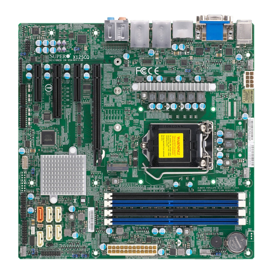
Introduction Congratulations on purchasing your computer motherboard from an industry leader. Supermicro motherboards are designed to provide you with the highest standards in quality and performance. In additon to the motherboard, several important parts that are included in the retail box are listed below. - Page 9 Chapter 1: Introduction Figure 1-1. X12SCQ Motherboard Image Note: All graphics shown in this manual were based upon the latest PCB revision available at the time of publication of the manual. The motherboard you received may or may not look exactly the same as the graphics shown in this manual.
- Page 10 Super X12SCQ User's Manual Figure 1-2. X12SCQ Motherboard Layout (not drawn to scale) DVI-D/VGA AUDIO FP HDMI/DP JPL2 HD AUDIO USB0/1 DESIGNED IN USA LAN2 KB/MOUSE LAN1 X12SCQ JPAC1 USB8/9(3.2) USB6/7(3.2) REV:1.00 JGP1 MH12 JPL1 MH11 Intel Q470E PCIe M.2-M1...
-
Page 11: Quick Reference
SLOT7 USB0/1 HDMI/DP SLOT6 KB/Mouse SLOT4 DVI-D/VGA AUDIO FP HDMI/DP AUDIO FP JPL2 HD AUDIO USB0/1 DESIGNED IN USA LAN2 LAN1 KB/MOUSE X12SCQ JPAC1 JPAC1 USB8/9(3.2) USB6/7(3.2) REV:1.00 JGP1 FAN4 MH12 JPL1 JGP1 JPW2 MH11 COM34 COM12 USB10/11 Intel JPME2... -
Page 12: Quick Reference Table
Super X12SCQ User's Manual Quick Reference Table Jumper Description Default Setting JAT1 ATX/AT Mode Pins 1-2 (ATX Mode) JBT1 CMOS Clear Open (Normal) JPAC1 Audio Enable/Disable Pins 1-2 (Enabled) JPL1, JPL2 LAN1/LAN2 Enable/Disable Pins 1-2 (Enabled) JPME2 Manufacturing Mode Pins 1-2 (Normal) - Page 13 Chapter 1: Introduction Connector Description SLOT5 CPU PCIe 3.0 x8 Slot (Lanes shared from SLOT7) SLOT6 PCH PCIe 3.0 x4 Slot SLOT7 CPU PCIe 3.0 x16 Slot Internal Speaker/Buzzer USB0/1 Back Panel Universal Serial Bus (USB) 2.0 Ports USB2/3, USB4/5 Front Accessible USB 2.0 Headers USB6/7, USB8/9 Back Panel USB 3.2 Ports...
-
Page 14: Motherboard Features
Super X12SCQ User's Manual Motherboard Features Motherboard Features • Supports an Intel 10th Gen Core i9/i7/i5/i3, Pentium, Celeron processor up to 10 cores in an LGA1200 socket Memory • Up to 128GB of Non-ECC UDIMM DDR4 memory with speeds of up to 2933MHz in four memory slots DIMM Size •... - Page 15 Chapter 1: Introduction Motherboard Features Peripheral Devices • Two USB 2.0 ports on the rear I/O panel (USB0/1) • Two USB 3.2 ports on the rear I/O panel (USB6/7, USB8/9) • Two front accessible USB 2.0 headers with two (2) USB connections (USB2/3, USB4/5) •...
- Page 16 Super X12SCQ User's Manual Figure 1-3. System Block Diagram PCIe x8 SLOT #5 PCIe Switch PCIe3.0_x16 SVID PVCC_CPU/GT PCIe x16 SLOT #7 IMVP8 8.0GT/s INTEL LGA1200 DDI1/Port B DVI-D DDR4 (CHA) Processor DIMMA1 (Black) DDI2/ Port C HDMI2.0 LSPCON DP1.2...
-
Page 17: Processor And Chipset Overview
1.2 Processor and Chipset Overview Built upon the functionality and capability of the Intel 10th Generation Core i/Pentium/Celeron series processor and the Intel Q470E chipset, the X12SCQ motherboard provides system performance, power efficiency, and feature sets to address the needs of next-generation computer users. -
Page 18: System Health Monitoring
Super X12SCQ User's Manual 1.4 System Health Monitoring Onboard Voltage Monitors The onboard voltage monitor will continuously scan crucial voltage levels. Once a voltage becomes unstable, a warning is given, or an error message is sent to the screen. The user can adjust the voltage thresholds to define the sensitivity of the voltage monitor. -
Page 19: Acpi Features
It is even more important for processors that have high CPU clock rates where noisy power transmission is present. The X12SCQ motherboard accommodates a 24-pin ATX power supply. Although most power supplies generally meet the specifications required by the CPU, some are inadequate. In addition, one 12V 8-pin power connection is also required to ensure adequate power supply to the system. -
Page 20: Chapter 2 Installation
Super X12SCQ User's Manual Chapter 2 Installation 2.1 Static-Sensitive Devices Electrostatic Discharge (ESD) can damage electronic com ponents. To avoid damaging your system board, it is important to handle it very carefully. The following measures are generally sufficient to protect your equipment from ESD. -
Page 21: Processor And Heatsink Installation
Thermal grease is pre-applied on a new heatsink. No additional thermal grease is needed. • Refer to the Supermicro website for updates on processor support. • All graphics in this manual are for illustrations only. Your components may look different. - Page 22 Super X12SCQ User's Manual 2. Gently lift the load lever to open the load plate. Remove the plastic protective cover. Do not touch the CPU socket contacts. 3. Locate the triangle on the CPU and CPU socket, which indicates the location of Pin 1.
-
Page 23: Installing An Active Cpu Heatsink With Fan
Chapter 2: Installation 5. Close the load plate, then gently push down the load lever into its locking position. CPU properly installed Load lever locked into place Note: You can only install the CPU in one direction. Make sure it is properly inserted into the socket before closing the load plate. - Page 24 Super X12SCQ User's Manual 6. Align the four heatsink fasteners with the mounting holes on the motherboard. Gently push down the fasteners in a diagonal order (Example: #1 and #2, then #3 and #4) into the mounting holes until you hear a click. Then lock the fasteners by turning each one 90°...
-
Page 25: Removing The Heatsink
Chapter 2: Installation Removing the Heatsink Note: We do not recommend that the CPU or heatsink be removed. However, if you do need to remove the heatsink, please follow the instructions below to remove the heatsink and prevent damage done to the CPU or other components. 1. -
Page 26: Motherboard Installation
Super X12SCQ User's Manual 2.3 Motherboard Installation All motherboards have standard mounting holes to fit different types of chassis. Make sure that the locations of all the mounting holes for both the motherboard and the chassis match. Although a chassis may have both plastic and metal mounting fasteners, metal ones are highly recommended because they ground the motherboard to the chassis. -
Page 27: Installing The Motherboard
Chapter 2: Installation Installing the Motherboard 1. Install the I/O shield into the back of the chassis, if applicable. 2. Locate the mounting holes on the motherboard. See the previous page for the location. 3. Locate the matching mounting holes on the chassis. Align the mounting holes on the motherboard against the mounting holes on the chassis. -
Page 28: Memory Support And Installation
Important: Exercise extreme care when installing or removing DIMM modules to pre- vent any possible damage. Memory Support The X12SCQ supports up to 128GB of Non-ECC UDIMM memory with speeds of up to 2933MHz in four memory slots. Refer to the table below for the recommended DIMM population order. -
Page 29: General Guidelines For Optimizing Memory Performance
However, to achieve the best memory performance, a balanced memory population is recommended. DVI-D/VGA AUDIO FP HDMI/DP JPL2 HD AUDIO USB0/1 DESIGNED IN USA LAN2 KB/MOUSE LAN1 X12SCQ JPAC1 USB8/9(3.2) USB6/7(3.2) REV:1.00 JGP1 MH12 JPL1 MH11 Intel Q470E PCIe M.2-M1... -
Page 30: Dimm Installation
Super X12SCQ User's Manual DIMM Installation 1. Insert DIMM modules in the following DVI-D/VGA AUDIO FP HDMI/DP JPL2 HD AUDIO DESIGNED IN USA USB0/1 KB/MOUSE LAN2 LAN1 X12SCQ order: DIMMA2, DIMMB2, then DIMMA1, JPAC1 USB8/9(3.2) USB6/7(3.2) REV:1.00 JGP1 MH12 JPL1 DIMMB1. -
Page 31: Rear I/O Ports
See Figure 2-1 below for the locations and descriptions of the various I/O ports on the rear of the motherboard. DVI-D/VGA AUDIO FP HDMI/DP JPL2 HD AUDIO USB0/1 DESIGNED IN USA LAN2 LAN1 KB/MOUSE X12SCQ JPAC1 USB8/9(3.2) USB6/7(3.2) REV:1.00 JGP1 MH12 JPL1 MH11 Intel Q470E PCIe M.2-M1... - Page 32 Super X12SCQ User's Manual HDMI Port One HDMI (High Definition Multimedia Interface) port is on the I/O back panel. This connector is used to display both high definition video and digital sound through an HDMI-capable display, using a single HDMI cable (not included).
- Page 33 Visual Interface) display. 1. DVI-D 2. VGA Port DVI-D/VGA AUDIO FP HDMI/DP JPL2 HD AUDIO USB0/1 DESIGNED IN USA LAN2 KB/MOUSE LAN1 X12SCQ JPAC1 USB8/9(3.2) USB6/7(3.2) REV:1.00 JGP1 MH12 JPL1 MH11 Intel Q470E PCIe M.2-M1 ALWAYS POPULATE BLUE SOCKET FIRST...
- Page 34 Super X12SCQ User's Manual LAN Ports Two Gigabit Ethernet ports (LAN1, LAN2) are located on the I/O back panel. All of these ports accept RJ45 cables. Please refer to the LED Indicator section for LAN LED information. LAN Port Pin Definition...
- Page 35 PCIe 1. USB0/1 JSD1 2. USB2/3 DVI-D/VGA AUDIO FP HDMI/DP JPL2 3. USB4/5 HD AUDIO USB0/1 DESIGNED IN USA LAN2 LAN1 KB/MOUSE X12SCQ JPAC1 USB8/9(3.2) USB6/7(3.2) REV:1.00 JGP1 4. USB6/7 MH12 JPL1 5. USB8/9 JLED MH11 6. USB10/11 DIMMA1 JBT1...
- Page 36 Super X12SCQ User's Manual High Definition Audio This motherboard features a 7.1+2 Channel High Definition Audio (HDA) codec that provides 10 DAC channels. The HD Audio connections simultaneously support multiple-streaming 7.1 sound playback with two channels of independent stereo output through the front panel stereo out for front, rear, center and subwoofer speakers.
-
Page 37: Front Control Panel
JF1 contains header pins for various buttons and indicators that are normally located on a control panel at the front of the chassis. These connectors are designed specifically for use with Supermicro chassis. See the figure below for the descriptions of the front control panel buttons and LED indicators. - Page 38 Super X12SCQ User's Manual Power Button The Power Button connection is located on pins 1 and 2 of JF1. Momentarily contacting both pins will power on/off the system. This button can also be configured to function as a suspend button (with a setting in the BIOS - see Chapter 4). To turn off the power when the system is in suspend mode, press the button for 4 seconds or longer.
- Page 39 Chapter 2: Installation Overheat (OH)/Fan Fail Connect an LED cable to pins 7 and 8 of the Front Control Panel to use the Overheat/Fan Fail LED connections. The LED on pin 8 provides warnings of overheating or fan failure. Refer to the tables below for pin definitions. OH/Fan Fail Indicator OH/Fan Fail LED Pin Definitions (JF1)
- Page 40 Super X12SCQ User's Manual HDD LED The HDD LED connection is located on pins 13 and 14 of JF1. Attach a cable to pin 14 to show hard drive activity status. Refer to the table below for pin definitions. HDD LED...
-
Page 41: Connectors
Ground +3.3V 1. 24-Pin ATX Power DVI-D/VGA AUDIO FP HDMI/DP JPL2 HD AUDIO USB0/1 DESIGNED IN USA KB/MOUSE LAN2 LAN1 X12SCQ JPAC1 USB8/9(3.2) USB6/7(3.2) REV:1.00 JGP1 MH12 JPL1 MH11 Intel Q470E PCIe M.2-M1 ALWAYS POPULATE BLUE SOCKET FIRST UNB NON-ECC DDR4 DIMM REQUIRED... - Page 42 Super X12SCQ User's Manual 8-Pin Power Connector JPWR1 is an 8-pin 12V DC power input for the CPU that must be connected to the power supply. Refer to the table below for pin definitions.. 8-pin Power Pin Definitions Pin# Definition...
-
Page 43: Headers
1. FAN1 2. FAN2 DVI-D/VGA AUDIO FP HDMI/DP 3. FAN3 JPL2 HD AUDIO USB0/1 DESIGNED IN USA LAN2 KB/MOUSE LAN1 X12SCQ JPAC1 USB8/9(3.2) USB6/7(3.2) REV:1.00 4. FAN4 JGP1 MH12 JPL1 MH11 Intel Q470E PCIe M.2-M1 ALWAYS POPULATE BLUE SOCKET FIRST... - Page 44 Super X12SCQ User's Manual TPM/Port 80 Header A Trusted Platform Module (TPM)/Port 80 header is located at JTPM1 to provide TPM support and Port 80 connection. Use this header to enhance system performance and data security. Refer to the table below for pin definitions. Please go to the following link for more information on the TPM: http://www.supermicro.com/manuals/other/TPM.pdf.
- Page 45 1. Standby Power Header 2. SATA Disk On Module DVI-D/VGA AUDIO FP HDMI/DP JPL2 HD AUDIO USB0/1 DESIGNED IN USA LAN2 KB/MOUSE LAN1 X12SCQ JPAC1 USB8/9(3.2) USB6/7(3.2) REV:1.00 JGP1 MH12 JPL1 MH11 Intel Q470E PCIe M.2-M1 ALWAYS POPULATE BLUE SOCKET FIRST...
- Page 46 Super X12SCQ User's Manual Speaker/Buzzer Pins 1-4 are for the speaker. Please note that the speaker connector pins (1-4) are used with an external speaker. If you wish to use the onboard speaker, you should close pins 3-4 with a cap. Refer to the tables below for pin definitions.
- Page 47 PWR LED on JF1 1. 3-Pin Power LED DVI-D/VGA AUDIO FP HDMI/DP JPL2 HD AUDIO USB0/1 DESIGNED IN USA LAN2 KB/MOUSE LAN1 X12SCQ JPAC1 USB8/9(3.2) USB6/7(3.2) REV:1.00 JGP1 MH12 JPL1 MH11 Intel Q470E PCIe M.2-M1 ALWAYS POPULATE BLUE SOCKET FIRST...
- Page 48 This motherboard has six I-SATA 3.0 ports (I-SATA0 - I-SATA5). I-SATA0 can be used with Supermicro SuperDOMs that are yellow SATA DOM connectors with power pins built in, and do not require external power cables. Supermicro SuperDOMs are backwards compatible with regular SATA HDDs or SATA DOMs that need external power cables.
- Page 49 Definition Ground 1. General Purpose Header DVI-D/VGA AUDIO FP HDMI/DP JPL2 HD AUDIO DESIGNED IN USA USB0/1 LAN2 LAN1 KB/MOUSE X12SCQ JPAC1 USB8/9(3.2) USB6/7(3.2) REV:1.00 JGP1 MH12 JPL1 MH11 Intel Q470E PCIe M.2-M1 ALWAYS POPULATE BLUE SOCKET FIRST UNB NON-ECC DDR4 DIMM REQUIRED...
- Page 50 Super X12SCQ User's Manual Front Accessible Audio Header A 10-pin audio header located AUDIO FP allows you to use the onboard sound for audio playback. Connect an audio cable to this header to use this feature. Refer to the table below for pin definitions.
- Page 51 JGP1 Chapter 2: Installation COM Headers The motherboard has two COM headers that provides four serial connections (COM12, COM34) and supports RS-232 function, utilizing Supermicro PN: CBL-CDAT-0604 (not included). COM Header (COM12, COM34) Pin Definitions Pin# Definition Pin# Definition DCD4...
-
Page 52: Jumper Settings
Super X12SCQ User's Manual 2.8 Jumper Settings How Jumpers Work To modify the operation of the motherboard, jumpers can be used to choose between optional settings. Jumpers create shorts between two pins to change the function of the connector. Pin 1 is identified with a square solder pad on the printed circuit board. See the diagram below for an example of jumping pins 1 and 2. - Page 53 Pins 2-3 1. WatchDog 2. Power Mode Select DVI-D/VGA AUDIO FP HDMI/DP JPL2 HD AUDIO USB0/1 DESIGNED IN USA LAN2 KB/MOUSE LAN1 X12SCQ JPAC1 USB8/9(3.2) USB6/7(3.2) REV:1.00 JGP1 MH12 JPL1 MH11 Intel Q470E PCIe M.2-M1 ALWAYS POPULATE BLUE SOCKET FIRST...
- Page 54 Super X12SCQ User's Manual ME Manufacturing Mode Close pins 2-3 of jumper JPME2 to bypass SPI flash security and force the system to operate in the manufacturing mode, which will allow the user to flash the system firmware from a host server for system setting modifications.
- Page 55 1. LAN1 Enable/Disable 2. LAN2 Enable/Disable DVI-D/VGA AUDIO FP 3. TPM Enable/Disable HDMI/DP JPL2 HD AUDIO DESIGNED IN USA USB0/1 LAN2 LAN1 KB/MOUSE X12SCQ JPAC1 USB8/9(3.2) USB6/7(3.2) REV:1.00 JGP1 MH12 JPL1 MH11 Intel Q470E PCIe M.2-M1 ALWAYS POPULATE BLUE SOCKET FIRST...
-
Page 56: Led Indicators
Super X12SCQ User's Manual 2.9 LED Indicators Onboard Power LED The Onboard Power LED is located at LEDPWR on the motherboard. When this LED is on, the system is on. Be sure to turn off the system and unplug the power cord before removing or installing components. - Page 57 1Gbps 10Mbps 1. LAN Port LED DVI-D/VGA AUDIO FP HDMI/DP JPL2 HD AUDIO USB0/1 DESIGNED IN USA LAN2 KB/MOUSE LAN1 X12SCQ JPAC1 USB8/9(3.2) USB6/7(3.2) REV:1.00 JGP1 MH12 JPL1 MH11 Intel Q470E PCIe M.2-M1 ALWAYS POPULATE BLUE SOCKET FIRST UNB NON-ECC DDR4 DIMM REQUIRED...
-
Page 58: Chapter 3 Troubleshooting
Super X12SCQ User's Manual Chapter 3 Troubleshooting 3.1 Troubleshooting Procedures Use the following procedures to troubleshoot your system. If you have followed all of the procedures below and still need assistance, refer to the ‘Technical Support Procedures’ and/ or ‘Returning Merchandise for Service’ section(s) in this chapter. Always disconnect the AC power cord before adding, changing or installing any non hot-swap hardware components. -
Page 59: No Video
Chapter 3: Troubleshooting No Video 1. If the power is on, but you have no video, remove all add-on cards and cables. 2. Use the speaker to determine if any beep codes are present. Refer to Appendix A for details on beep codes. 3. -
Page 60: Losing The System's Setup Configuration
Super X12SCQ User's Manual Losing the System's Setup Configuration 1. Make sure that you are using a high-quality power supply. A poor-quality power supply may cause the system to lose the CMOS setup information. Refer to Chapter 2 for details on recommended power supplies. - Page 61 Chapter 3: Troubleshooting 3. Using the minimum configuration for troubleshooting: Remove all unnecessary components (starting with add-on cards first), and use the minimum configuration (but with the CPU and a memory module installed) to identify the trouble areas. Refer to the steps listed in Section A above for proper troubleshooting procedures.
-
Page 62: Technical Support Procedures
Before contacting Technical Support, please take the following steps. Also, please note that as a motherboard manufacturer, Supermicro also sells motherboards through its channels, so it is best to first check with your distributor or reseller for troubleshooting services. They should know of any possible problems with the specific system configuration that was sold to you. -
Page 63: Frequently Asked Questions
Note: The SPI BIOS chip used on this motherboard cannot be removed. Send your motherboard back to our RMA Department at Supermicro for repair. For BIOS Recovery instructions, please refer to the AMI BIOS Recovery Instructions posted at http://www. -
Page 64: Battery Removal And Installation
Super X12SCQ User's Manual 3.4 Battery Removal and Installation Battery Removal To remove the onboard battery, follow the steps below: 1. Power off your system and unplug your power cable. 2. Locate the onboard battery as shown below. 3. Using a tool such as a pen or a small screwdriver, push the battery lock outwards to unlock it. -
Page 65: Returning Merchandise For Service
For faster service, you can also request a RMA authorization online (http://www.supermicro. com/RmaForm/). This warranty only covers normal consumer use and does not cover damages incurred in shipping or from failure due to the alternation, misuse, abuse or improper maintenance of products. -
Page 66: Chapter 4 Uefi Bios
Super X12SCQ User's Manual Chapter 4 UEFI BIOS 4.1 Introduction This chapter describes the AMIBIOS™ Setup utility for the motherboard. The BIOS is stored on a chip and can be easily upgraded using a flash program. Note: Due to periodic changes to the BIOS, some settings may have been added or deleted and might not yet be recorded in this manual. -
Page 67: Main Setup
Note: The time is in the 24-hour format. For example, 5:30 P.M. appears as 17:30:00. The date's default value is the BIOS build date after RTC reset. Supermicro X12SCQ BIOS Version This item displays the version of the BIOS ROM used in the system. - Page 68 Super X12SCQ User's Manual Memory Information Total Memory This item displays the total size of memory available in the system.
-
Page 69: Advanced
Chapter 4: BIOS 4.3 Advanced Use the arrow keys to select the Advanced menu and press <Enter> to access the menu items: Warning: Take caution when changing the Advanced settings. An incorrect value, a very high DRAM frequency, or an incorrect DRAM timing setting may make the system unstable. When this occurs, revert to default manufacturer settings. - Page 70 Super X12SCQ User's Manual High Precision Event Timer Select Enabled to activate the High Precision Event Timer (HPET) that produces periodic interrupts at a much higher frequency than a Real-time Clock (RTC) does in synchronizing multimedia streams, providing smooth playback and reducing the dependency on other timestamp calculation devices, such as an x86 RDTSC Instruction embedded in the CPU.
- Page 71 Chapter 4: BIOS Re-try Boot If this feature is enabled, the BIOS will automatically reboot the system from a specified boot device after its initial boot failure. The options are Disabled, Legacy Boot, and EFI Boot. Power Configuration Watch Dog Function If enabled, the Watch Dog Timer will allow the system to reset or generate NMI based on jumper settings when it is expired for more than five minutes.
- Page 72 Super X12SCQ User's Manual • CPU Speed • Processor Cores • Hyper Threading Technology • • SMX/TXT • 64-bit • EIST Technology • CPU C3 state • CPU C6 state • CPU C7 state • CPU C8 state • CPU C9 state •...
- Page 73 Chapter 4: BIOS Intel (VMX) Virtualization Technology Use this feature to enable the Vanderpool Technology. This technology allows the system to run several operating systems simultaneously. The options are Disabled and Enabled. Active Processor Cores This feature determines how many CPU cores will be activated for each CPU. When all is selected, all cores in the CPU will be activated.
- Page 74 Super X12SCQ User's Manual Power Limit 2 Use this item to configure the value for Power Limit 2. The value is in milli watts and the step size is 125mW. Use the number keys on your keyboard to enter the value. Enter 0 to use the manufacture default setting If the value is 0, the BIOS will set PL2 as 1.25* TDP.
- Page 75 Chapter 4: BIOS Chipset Configuration Warning: Setting the wrong values in the following features may cause the system to malfunc- tion. System Agent (SA) Configuration The following information will display: • SA PCIe Code Version • VT-d: Supported Memory Configuration ...
- Page 76 Super X12SCQ User's Manual Force ColdReset Use this feature to enable or disable a cold boot during a MRC execution. The options are Enabled and Disabled. Force Single Rank Select enabled to use only Rank 0 in each DIMM. The options are Disabled and Enabled.
- Page 77 Chapter 4: BIOS Aperture Size Use this feature to set the Aperture size, which is the size of system memory reserved by the BIOS for graphics device use. The options are 128MB, 256MB, 512MB, 1024MB, and 2048MB. DVMT Pre-Allocated Dynamic Video Memory Technology (DVMT) allows dynamic allocation of system memory to be used for video devices to ensure best use of available system memory based on the DVMT 5.0 platform.
- Page 78 Super X12SCQ User's Manual DMI Link ASPM Control Use this feature to set the ASPM (Active State Power Management) state on the SA (System Agent) side of the DMI Link. The options are Disable, L0s, L1, and L0sL1. DMI Extended Sync Control Use this feature to enable or disable the DMI extended synchronization.
- Page 79 Chapter 4: BIOS VT-d Select Enabled to activate Intel Virtualization Technology support for Direct I/O VT-d by reporting the I/O device assignments to VMM through the DMAR ACPI Tables. This feature offers fully-protected I/O resource-sharing across the Intel platforms, providing the user with greater reliability, security and availability in networking and data-sharing.
- Page 80 Super X12SCQ User's Manual L1 Substates Use this feature to set the PCI Express L1 Substates. The options are Disabled, L1.1, and L1.1 & L1.2. PCIe Speed Use this feature to select the PCI Express port speed. The options are Auto, Gen1, Gen2, and Gen3.
- Page 81 Chapter 4: BIOS Change Settings This feature specifies the base I/O port address and the Interrupt Request address of a serial port specified by the user. Select Auto to allow the BIOS to automatically assign the base I/O and IRQ address. The options are Auto, (IO=3F8h; IRQ=3;), (IO=3F8h; IRQ=3, 4, 5 ,6 ,7, 10, 11,12;), (IO=2F8h;...
- Page 82 Super X12SCQ User's Manual Serial Port 4 Configuration Serial Port Select Enabled to enable the selected onboard serial port. The options are Disabled and Enabled. Device Settings This feature displays the status of a serial port specified by the user.
- Page 83 Chapter 4: BIOS DNS addresses Interface ID This feature shows the interface ID for the specified network device. DAD Transmit Count This feature sends Neighbor Solicitation messages while performing a Duplicate Address Detection (DAD) to make sure there is no IP address duplication. A value of zero means a DAD has not been performed.
- Page 84 Super X12SCQ User's Manual CIRA Configuration CIRA Configuration Activate Remote Assistance Process Use this feature to activate Remote Assistance. Enabling this feature will also trigger the CIRCA boot. The options are Disabled and Enabled. *If the feature above is set to Enabled, the feature below will be available for...
- Page 85 Chapter 4: BIOS OEM Flags Settings MEBx Hotkey Pressed Use this feature to specify whether the MEBx hotkey should be enabled during the system boot. The options are Disabled and Enabled. MEBx Selection Screen Use this feature to select the type of MEBx selection screen. Press 1 to enter the ME Configuration screen and 2 to initiate a remote connection.
- Page 86 Super X12SCQ User's Manual PCI PERR/SERR Support Use this feature to enable or disable the runtime event for PCI errors. The options are Disabled and Enabled. Above 4G MMIO BIOS Assignment (Available if the system supports 64-bit PCI decoding) Select Enabled to decode a PCI device that supports 64-bit in the space above 4G Address.
- Page 87 Chapter 4: BIOS Onboard LAN1 Option ROM Use this feature to select which firmware function to be loaded for LAN Port1 used for system boot. The options are Disabled and EFI. Network Stack Select Enabled to enable PXE (Preboot Execution Environment) or UEFI (Unified Extensible Firmware Interface) for network stack support.
- Page 88 Super X12SCQ User's Manual RAID Device ID Use this feature to select the RAID device ID. The options are iRST Mode and Alternate. Storage Option ROM/UEFI Driver Select UEFI to load the EFI driver for system boot. Select Legacy to load a legacy driver for system boot.
- Page 89 Chapter 4: BIOS *If the feature above is set to Enabled, the following features will be available for configuration: COM1 Console Redirection Settings Use this feature to specify how the host computer will exchange data with the client computer, which is the remote computer used by the user. COM1 Terminal Type This feature allows the user to select the target terminal emulation type for Console Redirection.
- Page 90 Super X12SCQ User's Manual COM1 VT-UTF8 Combo Key Support Select Enabled to enable VT-UTF8 Combination Key support for ANSI/VT100 terminals. The options are Disabled and Enabled. COM1 Recorder Mode Select Enabled to capture the data displayed on a terminal and send it as text messages to a remote server.
- Page 91 Chapter 4: BIOS COM2 Bits per second Use this feature to set the transmission speed for a serial port used in Console Redirection. Make sure that the same speed is used in the host computer and the client computer. A lower transmission speed may be required for long and busy lines.
- Page 92 Super X12SCQ User's Manual COM2 Putty KeyPad This feature selects Function Keys and KeyPad settings for Putty, which is a terminal emulator designed for the Windows OS. The options are VT100, LINUX, XTERMR6, SCO, ESCN, and VT400. COM2 Redirection After BIOS POST Use this feature to enable or disable legacy Console Redirection after BIOS POST.
- Page 93 Chapter 4: BIOS COM3 Parity A parity bit can be sent along with regular data bits to detect data transmission errors. Select Even if the parity bit is set to 0, and the number of 1's in data bits is even. Select Odd if the parity bit is set to 0, and the number of 1's in data bits is odd.
- Page 94 Super X12SCQ User's Manual COM4 Console Redirection Select Enabled to use the port for Console Redirection. The options are Disabled and Enabled. *If the feature above is set to Enabled, the following features will become available for configuration: COM4 Console Redirection Settings Use this feature to specify how the host computer will exchange data with the client computer, which is the remote computer used by the user.
- Page 95 Chapter 4: BIOS COM4 Flow Control Use this feature to set the flow control for Console Redirection to prevent data loss caused by buffer overflow. Send a "Stop" signal to stop sending data when the receiving buffer is full. Send a "Start" signal to start sending data when the receiving buffer is empty. The options are None and Hardware RTS/CTS.
- Page 96 Super X12SCQ User's Manual Console Redirection Settings AMT SOL Terminal Type Use this feature to select the target terminal emulation type for Console Redirection. Select VT100 to use the ASCII Character set. Select VT100+ to add color and function key support. Select ANSI to use the Extended ASCII Character Set. Select VT-UTF8 to use UTF8 encoding to map Unicode characters into one or more bytes.
- Page 97 Chapter 4: BIOS AMT SOL Recorder Mode Select Enabled to capture the data displayed on a terminal and send it as text messages to a remote server. The options are Disabled and Enabled. AMT SOL Resolution 100x31 Select Enabled for extended-terminal resolution support. The options are Disabled and Enabled.
- Page 98 Super X12SCQ User's Manual Terminal Type Use this feature to select the target terminal emulation type for Console Redirection. Select VT100 to use the ASCII character set. Select VT100+ to add color and function key support. Select ANSI to use the extended ASCII character set. Select VT-UTF8 to use UTF8 encoding to map Unicode characters into one or more bytes.
- Page 99 Chapter 4: BIOS SHA-1 PCR Bank Use this feature to disable or enable the SHA-1 Platform Configuration Register (PCR) bank for the installed TPM device. The options are Disabled and Enabled. SHA256 PCR Bank Use this feature to disable or enable the SHA256 Platform Configuration Register (PCR) bank for the installed TPM device.
- Page 100 Super X12SCQ User's Manual USB Configuration USB Configuration USB Module Version USB Controllers USB Devices Legacy USB Support Select Enabled to support onboard legacy USB devices. Select Auto to disable legacy support if there are no legacy USB devices present. Select Disable to have all USB devices available for EFI applications only.
- Page 101 Chapter 4: BIOS Add an Attempt Delete Attempts Change Attempt Order Intel(R) I210 Gigabit Network Connection - 3C:EC:EF:3C:C7:71 NIC Configuration Link Speed Use this feature to specify the port speed used for the selected boot protocol. The options are Auto Negotiated, 10 Mbps Half, 10 Mbps Full, 100 Mbps Half, and 100 Mbps Full.
- Page 102 Super X12SCQ User's Manual Adapter PBA PCI Device ID PCI Address MAC Address Driver Health This feature provides the health status for the network drivers and controllers. Intel(R) PRO/1000 6.7.05 PCI-E Controller 9535bd98 Child 0 Intel(R) I210 Gigabit Network Connection Intel(R) Gigabit 0.0.29...
-
Page 103: Event Logs
Chapter 4: BIOS 4.4 Event Logs Use this menu to configure Event Log settings. Change SMBIOS Event Log Settings Enabling/Disabling Options SMBIOS Event Log Change this feature to enable or disable all features of the SMBIOS Event Logging during system boot. The options are Disabled and Enabled. Erasing Settings Erase Event Log If No is selected, data stored in the event log will not be erased. - Page 104 Super X12SCQ User's Manual SMBIOS Event Log Standard Settings Log System Boot Event This option toggles the System Boot Event logging to enabled or disabled. The options are Disabled and Enabled. MECI The Multiple Event Count Increment (MECI) counter counts the number of occurences that a duplicate event must happen before the MECI counter is incremented.
-
Page 105: Thermal & Fan
Chapter 4: BIOS 4.5 Thermal & Fan Use this menu to view System Health settings. System Health • CPU Temperature • PCH Temperature • System Temperature • Peripheral Temperature • AOC/AOM/Riser Onboard Temperature Fan Speed Control Use this feature to select the fan speed mode. The options are Standard and Full Speed. •... - Page 106 Super X12SCQ User's Manual • • VDIMM • 5VCC • AVCC • 3.3VCC • • VBAT...
-
Page 107: Security
Chapter 4: BIOS 4.6 Security Use this menu to configure the following security settings for the system. Administrator Password Press Enter to create a new, or change an existing, Administrator password. Hard Drive Security Frozen Use this feature to enable or disable the BIOS security frozen command for SATA and NVMe devices. - Page 108 Super X12SCQ User's Manual Secure Boot Mode Use this item to configure Secure Boot variables without authentication. The options are Standard and Custom. CSM Support This feature is for manufacturing debugging purposes. The options are Disable and Enable. Enter Audit Mode Select this feature to enter the audit mode to configure PK.
- Page 109 Chapter 4: BIOS Secure Boot Variable Platform Key (PK) Update Select Yes to load the new Platform Keys (PK) from the manufacturer's defaults. Select No to load the Platform Keys from a file. The options are Yes and No. ...
- Page 110 Super X12SCQ User's Manual Authorized TimeStamps Update Select Yes to load the DBT from the manufacturer's defaults. Select No to load the DBT from a file. The options are Yes and No. Append Select Yes to add the DBT from the manufacturer's defaults list to the existing DBT. Select No to load the DBT from a file.
- Page 111 Chapter 4: BIOS 4.7 Boot Use this menu to configure Boot settings. Boot Mode Select Use this item to select the type of device that the system is going to boot from. The options are Legacy, UEFI, and DUAL. Fixed Boot Order Priorities This option prioritizes the order of bootable devices that the system boots from.
- Page 112 Super X12SCQ User's Manual • Legacy/UEFI/Dual Boot Option #8 • Legacy/UEFI/Dual Boot Option #9 Delete Boot Option This feature allows the user to select a boot device to delete from the boot priority list. Delete Boot Option Use this item to remove an EFI boot option from the boot priority list.
- Page 113 Chapter 4: BIOS 4.8 Save & Exit Use this menu to save settings and exit from the BIOS. Save Options Discard Changes and Exit Select this option to quit the BIOS Setup without making any permanent changes to the system configuration, and reboot the computer. Select Discard Changes and Exit from the Save &...
- Page 114 Super X12SCQ User's Manual Restore Optimized Defaults To set this feature, select Restore Defaults from the Save & Exit menu and press <Enter>. These are factory settings designed for maximum system stability, but not for maximum performance. Save As User Defaults To set this feature, select Save as User Defaults from the Save &...
- Page 115 Appendix A: BIOS Codes Appendix A BIOS Codes A.1 BIOS Error POST (Beep) Codes During the POST (Power-On Self-Test) routines, which are performed each time the system is powered on, errors may occur. Non-fatal errors are those which, in most cases, allow the system to continue the boot-up process.
- Page 116 When BIOS performs the Power On Self Test, it writes checkpoint codes to I/O port 0080h. If the computer cannot complete the boot process, a diagnostic card can be attached to the computer to read I/O port 0080h (Supermicro p/n AOC-LPC80-20). For information on AMI updates, please refer to http://www.ami.com/products/.
- Page 117 1. Create a method to access the MS Windows installation ISO file. That might be a DVD, perhaps using an external USB/SATA DVD drive or a USB flash drive. 2. Retrieve the proper RST/RSTe driver. Go to the Supermicro web page for your motherboard and click on "Download the Latest Drivers and Utilities", select the proper driver, and copy it to a USB flash drive.
- Page 118 Super X12SCQ User's Manual 4. During Windows Setup, continue to the dialog where you select the drives on which to install Windows. If the disk you want to use is not listed, click on “Load driver” link at the bottom left corner.
- Page 119 The Supermicro website contains drivers and utilities for your system at https://www. supermicro.com/wftp/driver. Some of these must be installed, such as the chipset driver. After accessing the website, go into the CDR_Images (in the parent directory of the above link) and locate the ISO file for your motherboard. Download this file to a USB flash drive or a DVD.
- Page 120 B.3 SuperDoctor ® The Supermicro SuperDoctor 5 is a program that functions in a command-line or web-based interface for Windows and Linux operating systems. The program monitors such system health information as CPU temperature, system voltages, system power consumption, fan speed, and provides alerts via email or Simple Network Management Protocol (SNMP).
- Page 121 The following statements are industry standard warnings, provided to warn the user of situations which have the potential for bodily injury. Should you have questions or experience difficulty, contact Supermicro's Technical Support department for assistance. Only certified technicians should attempt to install or configure components.
- Page 122 Super X12SCQ User's Manual Attention Danger d'explosion si la pile n'est pas remplacée correctement. Ne la remplacer que par une pile de type semblable ou équivalent, recommandée par le fabricant. Jeter les piles usagées conformément aux instructions du fabricant. ¡Advertencia! Existe peligro de explosión si la batería se reemplaza de manera incorrecta.
- Page 123 Appendix C: Standardized Warning Statements Product Disposal Warning! Ultimate disposal of this product should be handled according to all national laws and regulations. 製品の廃棄 この製品を廃棄処分する場合、 国の関係する全ての法律 ・ 条例に従い処理する必要があります。 警告 本产品的废弃处理应根据所有国家的法律和规章进行。 警告 本產品的廢棄處理應根據所有國家的法律和規章進行。 Warnung Die Entsorgung dieses Produkts sollte gemäß allen Bestimmungen und Gesetzen des Landes erfolgen.
- Page 124 Warning: Do not upgrade the BIOS unless your system has a BIOS-related issue. Flashing the wrong BIOS can cause irreparable damage to the system. In no event shall Supermicro be liable for direct, indirect, special, incidental, or consequential damages arising from a BIOS update.
- Page 125 USB device or a writable CD/DVD. Note 1: If you cannot locate the "Super.ROM" file in your driver disk, visit our website www.supermicro.com to download the BIOS package. Extract the BIOS binary im- age into a USB flash device and rename it "Super.ROM" for the BIOS recovery use.
- Page 126 Super X12SCQ User's Manual Note 2: Before recovering the main BIOS image, confirm that the "Super.ROM" bi- nary image file you download is the same version or a close version meant for your motherboard. 2. Insert the USB device that contains the new BIOS image ("Super.ROM") into your USB port and reset the system until the following screen appears: 3.
- Page 127 Appendix D: UEFI BIOS Recovery 4. When the screen as shown above displays, use the arrow keys to select the item "Proceed with flash update" and press the <Enter> key. You will see the BIOS recovery progress as shown in the screen below: Note: Do not interrupt the BIOS flashing process until it has completed.
- Page 128 Super X12SCQ User's Manual 8. When the UEFI Shell prompt appears, type fs# to change the device directory path. Go to the directory that contains the BIOS package you extracted earlier from Step 6. Enter flash.nsh BIOSname.### at the prompt to start the BIOS update process.
Need help?
Do you have a question about the X12SCQ and is the answer not in the manual?
Questions and answers