Table of Contents
Advertisement
Available languages
Available languages
Quick Links
BEDIENUNG UND INSTALLATION
OPERATION AND INSTALLATION
UTILISATION ET INSTALLATION
USO E INSTALLAZIONE
OBSLUHA A INSTALACE
OBSŁUGA I INSTALACJA
Pufferspeicher mit Heizflansch und Wärmepumpen-Kompaktinstallationen | Buffer cylinder
with flanged immersion heater and compact heat pump installations | Ballon tampon avec
résistance électrique à bride et kit hydraulique pompe à chaleur | Serbatoio tampone
con flangia di riscaldamento e installazioni compatte per pompe di calore | Akumulační
zásobník s topnou přírubou a kompaktními instalacemi tepelného čerpadla | Zbiornik
buforowy z kołnierzem grzejnym oraz instalacjami kompaktowymi dla pomp ciepła
» SBP 100
» SBP-HF
» WPKI-H E
» WPKI-P E
» WPKI-W E
» WPKI-V
60
40
80
°C
20
100
0
120
2
1
0
bar
65°C
60
60
40
°C
80
40
°C
80
20
100
20
100
0
120
0
120
3
4
Advertisement
Chapters
Table of Contents
Troubleshooting

Related Manuals for STIEBEL ELTRON SBP 100


Summary of Contents for STIEBEL ELTRON SBP 100
- Page 1 Akumulační zásobník s topnou přírubou a kompaktními instalacemi tepelného čerpadla | Zbiornik buforowy z kołnierzem grzejnym oraz instalacjami kompaktowymi dla pomp ciepła » SBP 100 » SBP-HF » WPKI-H E »...
-
Page 2: Table Of Contents
Maße und Anschlüsse ����������������������������������������� 16 15.2 Elektroschaltpläne und Anschlüsse ������������������������� 17 15.3 Leistungskennlinien der Umwälzpumpen ����������������� 18 15.4 Störfallbedingungen ������������������������������������������� 18 15.5 Angaben zum Energieverbrauch ���������������������������� 19 15.6 Datentabellen ���������������������������������������������������� 19 KUNDENDIENST UND GARANTIE UMWELT UND RECYCLING | SBP 100 www.stiebel-eltron.com... -
Page 3: Allgemeine Hinweise
Hinweise, deren Nichtbeachtung schwere Verletzungen Einsatz des Gerätes zur Erwärmung anderer Flüssigkeiten als Was- oder Tod zur Folge haben kann. ser oder auch mit Chemikalien versetzten Wassers wie z. B. Sole. VORSICHT Hinweise, deren Nichtbeachtung zu mittelschweren oder leichten Verletzungen führen kann. www.stiebel-eltron.com SBP 100|... -
Page 4: Allgemeine Sicherheitshinweise
Wasser auf. Die Wasserlei- tungen und das Sicherheitsventil werden durch das Gerät nicht Zur besseren und schnelleren Hilfe teilen Sie ihm die Nummer vor Frost geschützt. vom Typenschild mit (000000-0000-000000): 000000-0000-000000 Made in Germany | SBP 100 www.stiebel-eltron.com... -
Page 5: Sicherheit
Wärmepumpen-Anlage und speziell für den Speicher SBP 100 konzipiert. Als notwendiges Zubehör für die Wärmepumpen-Kompaktins- tallationen sind Umwälzpumpen erhältlich, die für den direkten Anschluss am Wärmepumpen-Manager zugelassen sind: - UP 25 7.0 E, Bestellnummer 232942 - UP 25 7.5 E, Bestellnummer 232943 www.stiebel-eltron.com SBP 100|... -
Page 6: Anschlussstück Mit Fühlerhülse
3 Dichtring 4 Entleerungsventil f Demontieren Sie das Entleerungsventil. f Bauen Sie die Flanschplatte aus. Lösen Sie dazu die 10 Schrauben. f Bauen Sie die Elektro-Zusatzheizung mit dem beiliegenden Dichtring ein. f Stecken Sie die Isolierplatte auf. | SBP 100 www.stiebel-eltron.com... - Page 7 Führen Sie den Begrenzerfühler und den Reglerfühler in das Fühlerrohr ein, bis der Begrenzerfühler einrastet. Beachten Sie die Eintauchtiefen der Regler-Begrenzer-Kombination (siehe Kapitel „Technische Daten / Maße und Anschlüsse“). f Stecken Sie den Stecker auf die Elektro-Zusatzheizung. www.stiebel-eltron.com SBP 100|...
-
Page 8: Montage Des Gerätes
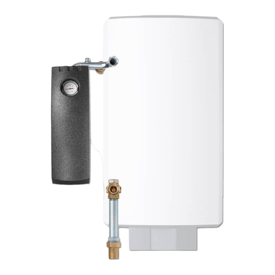
Ziehen Sie den Temperatur-Einstellknopf ab. 6 Kugelabsperrventil f Montieren Sie die Unterkappe. 7 Anschlussrohrbogen G 1 ¼ mit Anschluss für f Befestigen Sie den Regler mit den Schrauben an der Sicherheitsventil Unterkappe. 8 Wandhalterung f Stecken Sie den Temperatur-Einstellknopf auf. | SBP 100 www.stiebel-eltron.com... - Page 9 5 Kugelabsperrventil 6 Thermometer Wärmepumpen-Rücklauf 7 Anschlussstück G 1 mit Kugelabsperrventil und 8 Anschlussstück G 1 ¼ mit Anschluss für ein Entleerungsventil Rückschlagventil sowie Druckausdehnungsgefäß 9 Kugelabsperrventil 10 Anschlussstück G 1 ¼ mit Tauchhülse für Rücklauffühler 11 EPS-Dämmteile www.stiebel-eltron.com SBP 100|...
- Page 10 Sachschaden lichen Bauteile zum Anschluss der Wärmepumpe WPF an den Zwischen dem Sicherheitsventil und dem Wärmeerzeuger Speicher SBP 100 und an den Warmwasserspeicher. dürfen sich keine Absperreinrichtungen befinden. Alle vormontierten Bauteile sind bei Auslieferung eingedichtet. Die Montage wird in den folgenden Kapiteln beschrieben: f Wir empfehlen, vor der Montage am Speicher die Bauteile der Wärmepumpen-Kompaktinstallationen und die Umwälz-...
- Page 11 Schließen Sie das Druckausdehnungsgefäß und das Entlee- rungsventil an. f Montieren Sie „Ladestation Vorlauf opt.“ und „Ladestation Rücklauf opt.“. f Montieren Sie die EPS-Dämmteile. f Kürzen Sie ggf. die Gewindestange der Wandhalterung pas- send zum Abstand des Speichers zur Wand. www.stiebel-eltron.com SBP 100|...
- Page 12 WPKI-W E f Bauen Sie das T-Stück mit Absperrventil in den Wärmepum- pen-Rücklauf ein. f Montieren Sie „Ladestation Vorlauf opt.“, „Ladestation Rück- lauf opt.“ und „Speicher Rücklauf“. f Schließen Sie das Druckausdehnungsgefäß und das Entlee- rungsventil an. | SBP 100 www.stiebel-eltron.com...
- Page 13 Schließen Sie das Druckausdehnungsgefäß und das Entlee- rungsventil an. f Montieren Sie „Ladestation Vorlauf opt.“, „Ladestation Rück- lauf opt.“ und „Speicher Rücklauf“. f Montieren Sie die EPS-Dämmteile. f Kürzen Sie ggf. die Gewindestange der Wandhalterung pas- send zum Abstand des Speichers zur Wand. www.stiebel-eltron.com SBP 100|...
-
Page 14: Heizwasser-Anschluss
Entleeren Sie das Gerät. Siehe Kapitel „Wartung / Gerät öffnetem Sicherheitsventil das Wasser ungehindert ablaufen entleeren“. kann. f Montieren Sie die Abblaseleitung des Sicherheitsventils mit einer stetigen Abwärtsneigung in einem frostfreien Raum. f Die Abblaseöffnung des Sicherheitsventils muss zur Atmo- sphäre geöffnet bleiben. | SBP 100 www.stiebel-eltron.com... -
Page 15: Störungsbehebung
Entlüften oder Entleeren der Anlage wieder um 90°. Falls das Gerät für Wartungsarbeiten oder bei Frostgefahr zum Schutz der gesamten Installation entleert werden muss, gehen Sie folgendermaßen vor: 1 Rückstelltaste Sicherheitstemperaturbegrenzer 1 Entleerungsventil f Entleeren Sie mit dem Entleerungsventil das Gerät. www.stiebel-eltron.com SBP 100|... -
Page 16: Technische Daten
G 1 1/4 A Ladestation Vorlauf opt. Außengewinde G 1 1/4 A d46 Entlüftung Heizung Vorlauf Außengewinde G 1 1/4 A Heizung Rücklauf Außengewinde G 1 1/4 A Wandaufhängung I Wandaufhängung II Regler-Begrenzer-Kombination Eintauchtiefen 1 Begrenzerfühler 2 Reglerfühler | SBP 100 www.stiebel-eltron.com... -
Page 17: Elektroschaltpläne Und Anschlüsse
15.2 Elektroschaltpläne und Anschlüsse 2 kW, 1/N/PE ~ 230 V 4 kW, 1/N/PE ~ 230 V 4 kW, 2/N/PE ~ 400 V 6 kW, 3/N/PE ~ 400 V 1 Heizkörper je 2 kW ~ 230 V 2 Anschlussklemme (Netzanschlusskabel) 3 Anschlussklemme (Steuerleitung des Wärmepumpen-Managers) 4 Sicherheitstemperaturbegrenzer 5 Temperaturregler www.stiebel-eltron.com SBP 100|... -
Page 18: Leistungskennlinien Der Umwälzpumpen
Y Förderhöhe in m Z Leistungsaufnahme in W 15.4 Störfallbedingungen Im Störfall können Temperaturen bis 95 °C bei 0,6 MPa auftreten. 201620 UP 25 7.5 PCV X Fördervolumenstrom in m Y Förderhöhe in m Z Leistungsaufnahme in W | SBP 100 www.stiebel-eltron.com... -
Page 19: Angaben Zum Energieverbrauch
INSTALLATION Technische Daten 15.5 Angaben zum Energieverbrauch Produktdatenblatt: Warmwasserspeicher nach Verordnung (EU) Nr. 812/2013/ (S.I. 2019 Nr. 539 / Programm 2) SBP 100 185443 Hersteller STIEBEL ELTRON Modellkennung des Lieferanten SBP 100 Energieeffizienzklasse Warmhalteverluste S Speichervolumen V 15.6 Datentabellen SBP 100... -
Page 20: Kundendienst Und Garantie
Beschädigung eines Gerätes durch Diebstahl, Feuer, höhere oder schreiben Sie uns: Gewalt oder ähnliche Ursachen. Stiebel Eltron GmbH & Co. KG Über die vorstehend zugesagten Garantieleistungen hinausgehend – Kundendienst – kann der Endkunde nach dieser Garantie keine Ansprüche wegen mit- Dr.-Stiebel-Str. - Page 21 Materialien erreicht, um Deponien und die Umwelt zu ent- lasten. Damit leisten wir gemeinsam einen wichtigen Beitrag zum Umweltschutz. Entsorgung außerhalb Deutschlands Entsorgen Sie dieses Gerät fach- und sachgerecht nach den örtlich geltenden Vorschriften und Gesetzen. www.stiebel-eltron.com SBP 100|...
- Page 22 Dimensions and connections ��������������������������������� 36 15.2 Wiring diagrams and terminals ������������������������������ 37 15.3 Circulation pump rating curves ������������������������������ 38 15.4 Fault conditions ������������������������������������������������� 38 15.5 Details on energy consumption ������������������������������ 39 15.6 Data tables ������������������������������������������������������� 39 GUARANTEE ENVIRONMENT AND RECYCLING | SBP 100 www.stiebel-eltron.com...
-
Page 23: General Information
WARNING Failure to observe this information may result in serious injury or death. CAUTION Failure to observe this information may result in non-seri- ous or minor injury. www.stiebel-eltron.com SBP 100|... -
Page 24: General Safety Instructions
To facilitate and speed up your enquiry, please provide the serial es on in good time and heats the water. The appliance does not number from the type plate (000000-0000-000000): protect the water pipes and safety valve from frost. 000000-0000-000000 Made in Germany | SBP 100 www.stiebel-eltron.com... -
Page 25: Safety
Circulation pumps are available as required accessories for com- pact heat pump installations which are approved for direct con- nection to the heat pump manager: - UP 25/7.0 E, part number 232942 - UP 25/7.5 E, part number 232943 www.stiebel-eltron.com SBP 100|... -
Page 26: Connector With Sensor Sleeve
3 Seal ring 4 Drain valve f Remove the drain valve. f Remove the flange plate. To do this, undo the 10 screws. f Fit the immersion heater with the seal ring supplied. f Connect the insulating plate. | SBP 100 www.stiebel-eltron.com... - Page 27 Route the limiter sensor and the controller sensor into the sensor tube until the limiter sensor engages. Note the inser- tion depths of the controller-limiter combination (see chapter "Specification / Dimensions and connections"). f Insert the plug into the immersion heater. www.stiebel-eltron.com SBP 100|...
-
Page 28: Appliance Installation
Fit the lower cover. f Secure the controller to the lower cover using screws. f Fit the temperature selector. f Tick the selected connected load and voltage on the type plate with a ballpoint pen. | SBP 100 www.stiebel-eltron.com... - Page 29 8 Connector G 1 ¼ with connection for drain valve and expan- 7 Connector G 1 with ball shut-off valve and non-return valve sion vessel 9 Ball shut-off valve 10 Connector G 1 ¼ with sensor well for return temperature sensor 11 EPS insulation parts www.stiebel-eltron.com SBP 100|...
- Page 30 10 A/250 V AC or our WPM- sensor RBS relay set. f Connect the energy efficient circulation pumps approved by us (see chapter "Appliance description / Accessories"). For circulation pump rating curves, see chapter "Specification". | SBP 100 www.stiebel-eltron.com...
- Page 31 Install the "charging station flow opt." and "charging station return opt." f Install the EPS insulation parts. f If necessary, trim the wall mounting bracket threaded pin as appropriate for the distance between the cylinder and the wall. www.stiebel-eltron.com SBP 100|...
- Page 32 Fit the tee with shut-off valve into the heat pump return. f Install the "charging station flow opt.", "charging station re- turn opt." and "cylinder return". f Connect the expansion vessel and the drain valve. | SBP 100 www.stiebel-eltron.com...
- Page 33 Install the "charging station flow opt.", "charging station re- turn opt." and "cylinder return". f Install the EPS insulation parts. f If necessary, trim the wall mounting bracket threaded pin as appropriate for the distance between the cylinder and the wall. www.stiebel-eltron.com SBP 100|...
-
Page 34: Heating Water Connection
Fit the discharge pipe of the safety valve with a constant downward slope and in a room free from the risk of frost. f The safety valve discharge aperture must remain open to the atmosphere. | SBP 100 www.stiebel-eltron.com... -
Page 35: Troubleshooting
If the appliance needs to be drained for maintenance or to protect the whole installation when there is a risk of frost, proceed as follows: 1 Reset button for high limit safety cut-out 1 Drain valve f Drain the appliance using the drain valve. www.stiebel-eltron.com SBP 100|... -
Page 36: Specification
G 1 1/4 A d46 Ventilation Heating flow Male thread G 1 1/4 A Heating return Male thread G 1 1/4 A Wall mounting bracket I Wall mounting bracket II Controller-limiter combination insertion depths 1 Limiter sensor 2 Controller sensor | SBP 100 www.stiebel-eltron.com... -
Page 37: Wiring Diagrams And Terminals
4 kW, 1/N/PE ~ 230 V 4 kW, 2/N/PE ~ 400 V 6 kW, 3/N/PE ~ 400 V 1 Heating element, 2 kW ~ 230 V each 2 Terminal (power cable) 3 Terminal (heat pump manager control cable) 4 High limit safety cut-out 5 Temperature controller www.stiebel-eltron.com SBP 100|... -
Page 38: Circulation Pump Rating Curves
15.4 Fault conditions Should faults develop, temperatures up to 95 °C at 0.6 MPa can 201620 occur. UP 25 7.5 PCV X Delivery flow rate in m Y Delivery head in m Z Power consumption in W | SBP 100 www.stiebel-eltron.com... -
Page 39: Details On Energy Consumption
Germany. In countries 812/2013 / (S.I. 2019 No. 539 / Schedule 2) where our subsidiaries sell our products a guarantee can only SBP 100 be issued by those subsidiaries. Such guarantee is only grant- 185443 ed if the subsidiary has issued its own terms of guarantee. - Page 40 Schéma des connexions électriques et raccordements � 55 15.3 Courbes de puissance des circulateurs ��������������������� 56 15.4 Conditions d’incidents ����������������������������������������� 56 15.5 Indications relatives à la consommation énergétique ��� 57 15.6 Tableau de données �������������������������������������������� 57 GARANTIE ENVIRONNEMENT ET RECYCLAGE | SBP 100 www.stiebel-eltron.com...
-
Page 41: Remarques Générales
AVERTISSEMENT Caractérise des remarques dont le non-respect peut en- traîner de graves lésions, voire la mort. considérée comme non conforme. ATTENTION Caractérise des remarques dont le non-respect peut en- traîner des lésions légères ou moyennement graves. www.stiebel-eltron.com SBP 100|... -
Page 42: Consignes De Sécurité Générales
Communiquez-lui le numéro indiqué sur la plaque signalétique d’eau et la soupape de sécurité ne sont pas protégées du gel par pour qu’il puisse vous aider plus rapidement et plus efficacement l’appareil. (000000-0000-000000) : 000000-0000-000000 Made in Germany | SBP 100 www.stiebel-eltron.com... -
Page 43: Sécurité
Des circulateurs sont disponibles en tant qu’accessoires indispen- sables pour le kit hydraulique pompe à chaleur, ils sont homo- logués pour un raccordement direct au gestionnaire de pompe à chaleur : - UP 25 7.0 E, Réf. 232942 - UP 25 7.5 E, Réf. 232943 www.stiebel-eltron.com SBP 100|... -
Page 44: Raccord Avec Doigt De Gant
Déposez la vanne de vidange. f Déposez la plaque de bridage. Enlevez les 10 vis pour ce faire. f Mettez en place la résistance électrique d’appoint avec le joint d’étanchéité fourni. f Replacez la plaque d’isolation. | SBP 100 www.stiebel-eltron.com... - Page 45 Introduisez la sonde du régulateur et celle du limiteur de température dans le doigt de gant jusqu’à enclenchement de cette dernière. Respectez les profondeurs d’immersion de l’ensemble régulation-limiteur (voir le chapitre « Données techniques / Cotes et raccordements »). f Branchez la prise sur la résistance électrique d’appoint. www.stiebel-eltron.com SBP 100|...
-
Page 46: Montage De L'appareil
Retirez le bouton de réglage de température. 7 Coude G 1 ¼ avec piquage pour soupape de sécurité f Montez le cache inférieur. 8 Fixation murale f Fixez le régulateur sur le capot inférieur à l’aide des vis fournies. | SBP 100 www.stiebel-eltron.com... - Page 47 8 Raccord G 1 ¼ avec piquage pour vanne de vidange / vase 6 Thermomètre d’expansion 7 Raccord G 1 avec vanne à bille et clapet anti-retour 9 Vanne à boisseau 10 Raccord G 1 ¼ avec doigt de gant pour sonde Retour 11 Éléments d’isolation en PSE www.stiebel-eltron.com SBP 100|...
- Page 48 10 A/250 V CA ou bien notre kit contacteur WPM-RBS. f Installez un circulateur haute efficacité énergétique homo- logué par nous (voir chapitre « Description de l’appareil / Accessoires »). Courbes de puissance des circulateurs, voir chapitre « Données techniques ». | SBP 100 www.stiebel-eltron.com...
- Page 49 Installez le « Départ station de charge opt. » et le « Retour station de charge opt. ». f Montez les éléments d’isolation PSE. f Raccourcissez éventuellement la tige filetée du support mural pour adapter l’espacement entre le mur et le ballon. www.stiebel-eltron.com SBP 100|...
- Page 50 Intégrez le raccord en T avec vanne d’arrêt dans le circuit Re- tour pompe à chaleur. f Installez le « Départ station de charge opt. », le « Retour sta- tion de charge opt. » et le « Retour ballon ». f Branchez le vase d’expansion et la vanne de vidange. | SBP 100 www.stiebel-eltron.com...
- Page 51 Installez le « Départ station de charge opt. », le « Retour sta- tion de charge opt. » et le « Retour ballon ». f Montez les éléments d’isolation PSE. f Raccourcissez éventuellement la tige filetée du support mural pour adapter l’espacement entre le mur et le ballon. www.stiebel-eltron.com SBP 100|...
-
Page 52: Raccordement Eau Chaude
Installez la conduite de purge de la soupape de sécurité avec une inclinaison constante vers le bas dans un local à l’abri du gel. f L’ouverture de purge de la soupape de sécurité doit être re- liée à l’air libre. | SBP 100 www.stiebel-eltron.com... -
Page 53: Aide Au Dépannage
1 Bouton de réarmement du limiteur de sécurité 1 Vanne de vidange f Vider l’appareil au moyen de la vanne de vidange. www.stiebel-eltron.com SBP 100|... -
Page 54: Données Techniques
Départ chauffage Filetage mâle G 1 1/4 A Retour chauffage Filetage mâle G 1 1/4 A Support mural I Support mural II Profondeurs d’immersion de l’ensemble régulation-limiteur 1 Sonde du limiteur de température 2 Sonde du régulateur | SBP 100 www.stiebel-eltron.com... -
Page 55: Schéma Des Connexions Électriques Et Raccordements
6 kW, 3/N/PE ~ 400 V 1 Corps de chauffe 2 kW ~ 230 V chacun 2 Borne de raccordement (câble d’alimentation secteur) 3 Borne de raccordement (câble de commande du gestionnaire de pompe à chaleur) 4 Limiteur de sécurité 5 Thermostat www.stiebel-eltron.com SBP 100|... -
Page 56: Courbes De Puissance Des Circulateurs
15.4 Conditions d’incidents En cas de panne, la température peut atteindre 95 °C à 0,6 MPa. 201620 UP 25 7.5 PCV X Débit de refoulement en m Y Hauteur de refoulement en m Z Puissance électrique absorbée en W | SBP 100 www.stiebel-eltron.com... -
Page 57: Indications Relatives À La Consommation Énergétique
812/2013 duits dans le pays qui est seule habilitée à accorder une garan- SBP 100 tie. Une telle garantie ne pourra cependant être accordée que 185443 si la filiale a publié ses propres conditions de garantie. Il ne sera... - Page 58 Schemi elettrici e collegamenti ������������������������������ 73 15.3 Curve di potenza delle pompe di circolazione ������������ 74 15.4 Condizioni di guasto ������������������������������������������� 74 15.5 Dati relativi al consumo energetico ������������������������� 75 15.6 Tabelle dei dati �������������������������������������������������� 75 GARANZIA TUTELA DELL'AMBIENTE E RICICLAGGIO | SBP 100 www.stiebel-eltron.com...
-
Page 59: Avvertenze Generali
AVVERTENZA Note che, se non osservate, possono causare lesioni gravi o addirittura letali. glicolata. CAUTELA Note che, se non osservate, possono causare lesioni me- dio-gravi o lievi. www.stiebel-eltron.com SBP 100|... -
Page 60: Avvertenze Di Sicurezza Generali
è impostata su "freddo". 000000): L'apparecchio si accende in tempo e riscalda l'acqua. L'apparec- chio non protegge dal gelo le tubazioni idrauliche e la valvola di sicurezza. 000000-0000-000000 Made in Germany | SBP 100 www.stiebel-eltron.com... -
Page 61: Sicurezza
Come accessori necessari per le installazioni compatte per pompe di calore sono disponibili pompe di circolazione omologate per l'allacciamento diretto al quadretto di comando: - UP 25 7.0 E, numero d'ordine 232942 - UP 25 7.5 E, numero d'ordine 232943 www.stiebel-eltron.com SBP 100|... -
Page 62: Pezzo Di Raccordo Con Sensore
4 Valvola di scarico f Smontare la valvola di scarico. f Smontare la piastra flangiata. Allo scopo, svitare le 10 viti. f Montare il riscaldatore booster ausiliario con l'anello di tenu- ta fornito in dotazione. f Applicare la piastra isolante. | SBP 100 www.stiebel-eltron.com... - Page 63 Guidare il sensore del limitatore e quello del regolatore nel tubo apposito, fino a far ingranare il sensore del limitatore. Attenersi alle profondità di immersione della combinazione regolatore-limitatore (vedere il capitolo "Dati tecnici / Misure e allacciamenti"). f Inserire la spina sul riscaldatore booster ausiliario. www.stiebel-eltron.com SBP 100|...
-
Page 64: Montaggio Dell'apparecchio
3 Pezzo di raccordo G 1 con rubinetto di arresto a sfera f Rimuovere il selettore della temperatura. Riscaldamento mandata f Montare il pannello di chiusura inferiore. 4 Pezzo di raccordo G 1 con rubinetto di arresto a sfera 5 Termometro | SBP 100 www.stiebel-eltron.com... - Page 65 8 Pezzo di raccordo G 1 ¼ con allacciamento per una valvola di scarico e un serbatoio di espansione a pressione 9 Rubinetto di arresto a sfera 10 Pezzo di raccordo G 1 ¼ con guaina a immersione per senso- re di ritorno 11 Parti isolanti in EPS www.stiebel-eltron.com SBP 100|...
- Page 66 L'installazione compatta pompa di calore contiene tutti i compo- nenti necessari per l'allacciamento della pompa di calore WPF Danni materiali all'accumulatore SBP 100 e al boiler ACS. Tra la valvola di sicurezza e il generatore di calore non deve essere presente alcun dispositivo di intercettazione.
- Page 67 Montare la "Stazione carica mandata opz." e la "Stazione ca- rica ritorno opz.". f Montare le parti isolanti in EPS. f Se necessario, accorciare la barra filettata del supporto a pa- rete per adeguare la distanza tra l'accumulatore e la parete. www.stiebel-eltron.com SBP 100|...
- Page 68 Montare il raccordo a T con valvola di chiusura nel ritorno pompa di calore. f Montare la "Stazione carica mandata opz.", la "Stazione cari- ca ritorno opz." e l'"Accumulatore ritorno". f Collegare il serbatoio di espansione a pressione e la valvola di scarico. | SBP 100 www.stiebel-eltron.com...
- Page 69 Montare la "Stazione carica mandata opz.", la "Stazione cari- ca ritorno opz." e l'"Accumulatore ritorno". f Montare le parti isolanti in EPS. f Se necessario, accorciare la barra filettata del supporto a pa- rete per adeguare la distanza tra l'accumulatore e la parete. www.stiebel-eltron.com SBP 100|...
-
Page 70: Accessori Installazioni Compatte Per Pompe Di Calore
Montare la linea di scarico della valvola di sicurezza con inclinazione discendente costante in un locale protetto dal gelo. f L'apertura di sfiato della valvola di sicurezza deve rimanere aperta verso l'atmosfera. | SBP 100 www.stiebel-eltron.com... -
Page 71: Risoluzione Dei Guasti
Se occorre svuotare l'apparecchio per eseguire interventi di ma- nutenzione o perché sussiste pericolo di gelo, proteggere l'intero impianto, procedendo nel modo seguente: 1 Pulsante di reset limitatore di sicurezza della temperatura 1 Valvola di scarico f Svuotare l'apparecchio mediante la valvola di scarico. www.stiebel-eltron.com SBP 100|... -
Page 72: Dati Tecnici
Filettatura di tipo maschio G 1 1/4 A Riscaldamento ritorno Filettatura di tipo maschio G 1 1/4 A Montaggio a parete I Montaggio a parete II Profondità di immersione combinazione regolatore-limitatore 1 Sensore limitatore 2 Sensore regolatore | SBP 100 www.stiebel-eltron.com... -
Page 73: Schemi Elettrici E Collegamenti
4 kW, 2/N/PE ~ 400 V 6 kW, 3/N/PE ~ 400 V 1 Radiatori, ciascuno 2 kW ~ 230 V 2 Morsetto (cavo di collegamento alla rete) 3 Morsetto (cavo di controllo quadretto di comando) 4 Limitatore di sicurezza della temperatura 5 Unità di controllo temperatura www.stiebel-eltron.com SBP 100|... -
Page 74: Curve Di Potenza Delle Pompe Di Circolazione
In presenza di guasti, si raggiungono temperature fino a 95 °C ad 201620 una pressione di 0,6 MPa. UP 25 7.5 PCV X Flusso volumetrico alimentato in m Y Punto di consegna in m Z Potenza assorbita in W | SBP 100 www.stiebel-eltron.com... -
Page 75: Dati Relativi Al Consumo Energetico
Nei paesi in cui 812/2013/ (S.I. 2019 n. 539 / Programma 2) una delle nostre affiliate distribuisce i nostri prodotti, la garan- SBP 100 zia può essere prestata solo da tale affiliata. Questa garanzia 185443 può... - Page 76 Schémata elektrického zapojení a přípojky ��������������� 91 15.3 Výkonové charakteristiky oběhových čerpadel ����������� 92 15.4 Podmínky v případě poruchy ��������������������������������� 92 15.5 Údaje ke spotřebě energie ������������������������������������ 93 15.6 Tabulky dat ������������������������������������������������������� 93 ZÁRUKA ŽIVOTNÍ PROSTŘEDÍ A RECYKLACE | SBP 100 www.stiebel-eltron.com...
-
Page 77: Obecné Pokyny
úrazy. noucí směs. VÝSTRAHA Pokyny, jejichž nedodržení může mít za následek vážné nebo smrtelné úrazy. POZOR Pokyny, jejichž nedodržení může mít za následek středně vážné nebo lehké úrazy. www.stiebel-eltron.com SBP 100|... -
Page 78: Všeobecné Bezpečnostní Pokyny
„studený“ stupeň. Přístroj se včas zapne a ohřívá vodu. Přístroj nechrání před zamrznutím Pro lepší a rychlejší pomoc mu sdělte číslo (č. 000000-0000- vodovodní potrubí a pojistný ventil. 000000), které je uvedeno na typovém štítku: 000000-0000-000000 Made in Germany | SBP 100 www.stiebel-eltron.com... -
Page 79: Bezpečnost
Elektrická topná příruba je určena k pozdější instalaci. Kompaktní instalace tepelného čerpadla Kompaktní instalace tepelného čerpadla jsou součásti soustavy te- pelných čerpadel a jsou zvláště koncipovány pro zásobník SBP 100. Jako nezbytné příslušenství pro kompaktní instalace tepelného čerpadla jsou k dostání oběhová čerpadla, která jsou schválena pro přímé... -
Page 80: Připojovací Kus S Jímkou Snímače
2 Elektrické přídavné topení 3 Těsnicí kroužek 4 Vypouštěcí ventil f Demontujte vypouštěcí ventil. f Demontujte desku příruby. K tomu účelu povolte 10 šroubů. f Elektrické přídavné topení namontujte s přiloženým těsnicím kroužkem. f Nasuňte izolační desku. | SBP 100 www.stiebel-eltron.com... - Page 81 Žíly upevněte do držáku žil. f Snímač omezovače a regulátoru zaveďte do jímky snímače, aby se snímač omezovače zajistil. Dodržte hloubku ponoru kombinace regulátoru a omezovače (viz kapitola „Technické údaje/Rozměry a přípojky“). f Zástrčku zasuňte na elektrické přídavné topení. www.stiebel-eltron.com SBP 100|...
-
Page 82: Montáž Přístroje
Pamatujte, že přístroj musí být připojen k ochrannému WPKI-H E vodiči. Kompaktní instalace tepelného čerpadla obsahuje všechny po- třebné součásti k připojení topného systému k zásobníku SBP 100. Věcné škody Dodržujte údaje uvedené na typovém štítku. Uvedené napětí se musí shodovat se síťovým napětím. -
Page 83: Čerpadla
WPKI-P E WPKI-W E Kompaktní instalace tepelného čerpadla obsahuje všechny potřeb- Kompaktní instalace tepelného čerpadla obsahuje všechny potřeb- né součásti k připojení tepelného čerpadla k zásobníku SBP 100. né součásti k připojení k zásobníku teplé vody. °C °C Topná voda - TČ... - Page 84 6 Připojovací kus G 1 ¼ s ponornou jímkou pro snímač vratné WPM-RBS. větve f Připojujte námi schválená energeticky účinná oběhová čer- padla (viz kapitola „Popis zařízení / Příslušenství“). Výkonové charakteristiky oběhových čerpadel viz kapitola „Tech- nické údaje“. | SBP 100 www.stiebel-eltron.com...
- Page 85 Připojte tlakovou expanzní nádobu a vypouštěcí ventil. f Namontujte „Ohř. stanice výst. strana - přísl.“ a „Ohř. stanice vrat. strana - přísl.“. f Namontujte tlumicí díly EPS. f Závitovou tyč nástěnného držáku případně vhodně zkraťte na vzdálenost zásobníku od stěny. www.stiebel-eltron.com SBP 100|...
- Page 86 Tvarovku T s uzavíracím ventilem namontujte na vratnou stranu tepelného čerpadla. f Namontujte „Ohř. stanice výst. strana - přísl.“ a „Ohř. stanice vrat. strana - přísl.“ a „Vratná strana zásobníku“. f Připojte tlakovou expanzní nádobu a vypouštěcí ventil. | SBP 100 www.stiebel-eltron.com...
- Page 87 Namontujte „Ohř. stanice výst. strana - přísl.“ a „Ohř. stanice vrat. strana - přísl.“ a „Vratná strana zásobníku“. f Namontujte tlumicí díly EPS. f Závitovou tyč nástěnného držáku případně vhodně zkraťte na vzdálenost zásobníku od stěny. www.stiebel-eltron.com SBP 100|...
-
Page 88: Přípojka Topné Vody
Odtok dimenzujte tak, aby v případě zcela otevřeného pojist- ného ventilu mohla voda plynule odtékat. f Namontujte odtok pojistného ventilu s plynulým sklonem v nezamrzající místnosti. f Vypouštěcí otvor pojistného ventilu musí zůstat směrem do atmosféry otevřený. | SBP 100 www.stiebel-eltron.com... -
Page 89: Odstraňování Poruch
90°. Pokud je nutno přístroj z důvodu údržby nebo při nebezpečí za- mrznutí z důvodu ochrany kompletní instalace vyprázdnit, postu- pujte takto: 1 Tlačítko Reset bezpečnostního omezovače teploty 1 Vypouštěcí ventil f Vypusťte vypouštěcí ventil přístroje. www.stiebel-eltron.com SBP 100|... -
Page 90: Technické Údaje
Odvzdušnění Topení vstup.strana Vnější závit G 1 1/4 A Topení vratná strana Vnější závit G 1 1/4 A Zavěšení na zeď I Zavěšení na zeď II Hloubky ponoru kombinace regulátor-omezovač 1 Snímač bezpečnostní pojistky 2 Snímač regulátoru | SBP 100 www.stiebel-eltron.com... -
Page 91: Schémata Elektrického Zapojení A Přípojky
4 kW, 1/N/PE ~ 230 V 4 kW, 2/N/PE ~ 400 V 6 kW, 3/N/PE ~ 400 V 1 Topná tělesa po 2 kW ~ 230 V 2 Připojovací svorka (přívodní kabel) 3 Připojovací svorka (řídicí rozvod regulátoru tepelných čerpadel) 4 Bezpečnostní omezovač teploty 5 Regulátor teploty www.stiebel-eltron.com SBP 100|... -
Page 92: Výkonové Charakteristiky Oběhových Čerpadel
Z Příkon ve W 15.4 Podmínky v případě poruchy V případě poruchy může dojít k teplotám až 95 °C při tlaku 0,6 MPa. 201620 UP 25 7.5 PCV X Čerpaný objemový průtok v m Y Dopravní výška v m Z Příkon ve W | SBP 100 www.stiebel-eltron.com... -
Page 93: Údaje Ke Spotřebě Energie
List technických údajů k výrobku: Zásobník teplé vody v souladu podmínky poskytované našimi firmami v Německu. V zemích, s nařízením (EU) č. 812/2013 ve kterých některá z našich dceřiných společností distribuuje SBP 100 naše výrobky, poskytuje záruku jenom tato dceřiná společnost. 185443 Takovou záruku lze poskytnout pouze tehdy, pokud dceřiná... - Page 94 - Otwór wylotowy zaworu bezpieczeństwa musi 15.3 Charakterystyki mocy pomp obiegowych �����������������110 być zawsze otwarty do atmosfery. 15.4 Warunki awaryjne ���������������������������������������������110 15.5 Dane dotyczące zużycia energii �����������������������������111 15.6 Tabele danych ��������������������������������������������������111 GWARANCJA OCHRONA ŚRODOWISKA NATURALNEGO I RECYCLING | SBP 100 www.stiebel-eltron.com...
-
Page 95: Wskazówki Ogólne
Wskazówki, których nieprzestrzeganie prowadzi do cięż- chemikaliów, np. solanki. kich obrażeń ciała lub śmierci. OSTRZEŻENIE Wskazówki, których nieprzestrzeganie może prowadzić do ciężkich obrażeń ciała lub śmierci. OSTROŻNIE Wskazówki, których nieprzestrzeganie może prowadzić do średnich lub lekkich obrażeń ciała. www.stiebel-eltron.com SBP 100|... -
Page 96: Ogólne Wskazówki Dotyczące Bezpieczeństwa
„zimna”. Urządzenie włącza się w odpowiedniej chwili i ogrzewa wodę. Urządzenie nie chroni przewodów wodo- ciągowych oraz zaworu bezpieczeństwa przed zamarznięciem. 000000-0000-000000 Made in Germany | SBP 100 www.stiebel-eltron.com... -
Page 97: Bezpieczeństwo
Jako niezbędny osprzęt do instalacji kompaktowych dla pomp ciepła dostępne są pompy obiegowe, które dopuszczone są do bezpośredniego podłączania regulatora pomp ciepła: - UP 25 7.0 E, numer katalogowy 232942 - UP 25 7.5 E, numer katalogowy 232943 www.stiebel-eltron.com SBP 100|... -
Page 98: Złącze Z Tuleją Czujnika
2 Elektryczne ogrzewanie dodatkowe 3 Pierścień uszczelniający 4 Zawór spustowy f Zdemontować zawór spustowy. f Wymontować płytę kołnierza. W tym celu odkręcić 10 śrub. f Zamontować elektryczne ogrzewanie dodatkowe z załączo- nym pierścieniem uszczelniającym. f Podłączyć płytę izolacyjną. | SBP 100 www.stiebel-eltron.com... - Page 99 Zamocować skrętki na uchwytach na skrętki. f Wprowadzić czujnik ogranicznika i regulator do tulei czujni- ka, aż do zatrzaśnięcia ogranicznika. Przestrzegać głębokości zanurzenia kombinacji regulator - ogranicznik (patrz rozdział „Dane techniczne / Wymiary i przyłącza”). f Wsunąć wtyczkę w elektryczne ogrzewanie dodatkowe www.stiebel-eltron.com SBP 100|...
-
Page 100: Montaż Urządzenia
Zdjąć pokrętło regulacyjne i pierścień ogranicznika. 6 Kulowy zawór odcinający f Zamontować pokrywę dolną. 7 Kolanko rury przyłączeniowej G 1 ¼ z przyłączem dla zaworu f Za pomocą załączonych śrub zamocować regulator na pokry- bezpieczeństwa wie dolnej. 8 Uchwyt ścienny | SBP 100 www.stiebel-eltron.com... - Page 101 8 Złącze G 1 ¼ z przyłączem dla zaworu spustowego oraz ci- 7 Złącze G 1 z kulowym zaworem odcinającym i zaworem śnieniowego naczynia wzbiorczego zwrotnym 9 Kulowy zawór odcinający 10 Złącze G 1 ¼ z tuleją zanurzeniową do czujnika powrotu 11 Elementy izolacyjne EPS www.stiebel-eltron.com SBP 100|...
- Page 102 10 A / 250 V AC lub nasz moduł przekaźnikowy WPM-RBS. f Podłączać dopuszczone przez naszą firmę energooszczędne pompy obiegowe (patrz rozdział „Opis urządzenia / Wyposa- żenie dodatkowe”). Charakterystyki mocy pomp obiegowych patrz rozdział „Dane techniczne”. | SBP 100 www.stiebel-eltron.com...
- Page 103 Podłączyć ciśnieniowe naczynie wzbiorcze i zawór spustowy. f Zamontować „Stacja ładowania wyjście, opcja” i „Stacja ła- dowania powrót, opcja”. f Zamontować elementy izolacyjne EPS. f Ewentualnie skrócić kołek gwintowany mocowania ścienne- go, aby pasował do odstępu zasobnika od ściany. www.stiebel-eltron.com SBP 100|...
- Page 104 5 Trójnik z zaworem odcinającym WPKI-W E f Zamontować trójnik z zaworem odcinającym do powrotu pompy ciepła. f Zamontować „Stacja ładowania wyjście, opcja”, „Stacja łado- wania powrót, opcja” i „Zasobnik powrót”. f Podłączyć ciśnieniowe naczynie wzbiorcze i zawór spustowy. | SBP 100 www.stiebel-eltron.com...
- Page 105 Podłączyć ciśnieniowe naczynie wzbiorcze i zawór spustowy. f Zamontować „Stacja ładowania wyjście, opcja”, „Stacja łado- wania powrót, opcja” i „Zasobnik powrót”. f Zamontować elementy izolacyjne EPS. f Ewentualnie skrócić kołek gwintowany mocowania ścienne- go, aby pasował do odstępu zasobnika od ściany. www.stiebel-eltron.com SBP 100|...
-
Page 106: Przyłącze Wody Grzewczej
Zamontować przewód odpływowy grupy zabezpieczającej przy zachowaniu stałego nachylenia, w pomieszczeniu wol- nym od mrozu. f Otwór wylotowy zaworu bezpieczeństwa musi być zawsze otwarty do atmosfery. | SBP 100 www.stiebel-eltron.com... -
Page 107: Usuwanie Usterek
Jeśli konieczne jest opróżnienie całej instalacji przed przystąpie- niem do prac konserwacyjnych lub w razie wystąpienia ryzyka zamarznięcia, należy postępować w następujący sposób: 1 Przycisk resetowania ogranicznika temperatury bezpieczeństwa 1 Zawór spustowy f Opróżnić urządzenie za pomocą zaworu spustowego. www.stiebel-eltron.com SBP 100|... -
Page 108: Dane Techniczne
G 1 1/4 A d46 Odpowietrzanie CO zasilanie Gwint zewnętrzny G 1 1/4 A CO powrót Gwint zewnętrzny G 1 1/4 A Uchwyt ścienny I Uchwyt ścienny II Głębokości zanurzenia kombinacji regulator - ogranicznik 1 Czujnik ogranicznika 2 Czujnik regulatora | SBP 100 www.stiebel-eltron.com... -
Page 109: Schematy Połączeń Elektrycznych I Podłączenia
4 kW, 2/N/PE ~ 400 V 6 kW, 3/N/PE ~ 400 V 1 Grzałki, każda 2 kW ~ 230 V 2 Zacisk przyłączeniowy (sieciowy przewód przyłączeniowy) 3 Zacisk przyłączeniowy (przewód sterujący regulatora pomp ciepła) 4 Ogranicznik temperatury bezpieczeństwa 5 Regulator temperatury www.stiebel-eltron.com SBP 100|... -
Page 110: Charakterystyki Mocy Pomp Obiegowych
Z Pobór mocy w W 15.4 Warunki awaryjne W przypadku awarii może wystąpić temperatura do 95 °C, przy 201620 ciśnieniu 0,6 MPa. UP 25 7.5 PCV X Strumień przepływu w m Y Wysokość podnoszenia w m Z Pobór mocy w W | SBP 100 www.stiebel-eltron.com... -
Page 111: Dane Dotyczące Zużycia Energii
Ponadto w z rozporządzeniem (UE) nr 812/2013 krajach, w których jedna z naszych spółek córek jest dystrybu- SBP 100 torem naszych produktów, gwarancji może udzielić wyłącznie 185443 ta spółka. Taka gwarancja obowiązuje tylko wówczas, gdy spół-... - Page 112 Hungary South Africa STIEBEL ELTRON Australia Pty. Ltd. STIEBEL ELTRON Kft. STIEBEL ELTRON Southern Africa (PT Y) Ltd 294 Salmon Street | Port Melbourne VIC 3207 Gyár u. 2 | 2040 Budaörs 30 Archimedes Road Tel. 03 9645-1833 | Fax 03 9644-5091 Tel.
Need help?
Do you have a question about the SBP 100 and is the answer not in the manual?
Questions and answers